EP0434931A2 - Lentilles de Fresnel acoustiques multiples à phase discrète et leur application à l'impression acoustique à jet d'encre - Google Patents
Lentilles de Fresnel acoustiques multiples à phase discrète et leur application à l'impression acoustique à jet d'encre Download PDFInfo
- Publication number
- EP0434931A2 EP0434931A2 EP90120920A EP90120920A EP0434931A2 EP 0434931 A2 EP0434931 A2 EP 0434931A2 EP 90120920 A EP90120920 A EP 90120920A EP 90120920 A EP90120920 A EP 90120920A EP 0434931 A2 EP0434931 A2 EP 0434931A2
- Authority
- EP
- European Patent Office
- Prior art keywords
- lens
- acoustic
- lenses
- substrate
- ink
- Prior art date
- Legal status (The legal status is an assumption and is not a legal conclusion. Google has not performed a legal analysis and makes no representation as to the accuracy of the status listed.)
- Granted
Links
Images


Classifications
-
- B—PERFORMING OPERATIONS; TRANSPORTING
- B41—PRINTING; LINING MACHINES; TYPEWRITERS; STAMPS
- B41J—TYPEWRITERS; SELECTIVE PRINTING MECHANISMS, i.e. MECHANISMS PRINTING OTHERWISE THAN FROM A FORME; CORRECTION OF TYPOGRAPHICAL ERRORS
- B41J2/00—Typewriters or selective printing mechanisms characterised by the printing or marking process for which they are designed
- B41J2/005—Typewriters or selective printing mechanisms characterised by the printing or marking process for which they are designed characterised by bringing liquid or particles selectively into contact with a printing material
- B41J2/01—Ink jet
- B41J2/135—Nozzles
- B41J2/14—Structure thereof only for on-demand ink jet heads
- B41J2/14008—Structure of acoustic ink jet print heads
-
- G—PHYSICS
- G10—MUSICAL INSTRUMENTS; ACOUSTICS
- G10K—SOUND-PRODUCING DEVICES; METHODS OR DEVICES FOR PROTECTING AGAINST, OR FOR DAMPING, NOISE OR OTHER ACOUSTIC WAVES IN GENERAL; ACOUSTICS NOT OTHERWISE PROVIDED FOR
- G10K11/00—Methods or devices for transmitting, conducting or directing sound in general; Methods or devices for protecting against, or for damping, noise or other acoustic waves in general
- G10K11/18—Methods or devices for transmitting, conducting or directing sound
- G10K11/26—Sound-focusing or directing, e.g. scanning
- G10K11/30—Sound-focusing or directing, e.g. scanning using refraction, e.g. acoustic lenses
-
- B—PERFORMING OPERATIONS; TRANSPORTING
- B41—PRINTING; LINING MACHINES; TYPEWRITERS; STAMPS
- B41J—TYPEWRITERS; SELECTIVE PRINTING MECHANISMS, i.e. MECHANISMS PRINTING OTHERWISE THAN FROM A FORME; CORRECTION OF TYPOGRAPHICAL ERRORS
- B41J2/00—Typewriters or selective printing mechanisms characterised by the printing or marking process for which they are designed
- B41J2/005—Typewriters or selective printing mechanisms characterised by the printing or marking process for which they are designed characterised by bringing liquid or particles selectively into contact with a printing material
- B41J2/01—Ink jet
- B41J2/135—Nozzles
- B41J2/14—Structure thereof only for on-demand ink jet heads
- B41J2002/14322—Print head without nozzle
Definitions
- This invention relates to acoustic focusing lenses and, more particularly, to multi-discrete-phase Fresnel acoustic focusing lenses for acoustic ink printing.
- Acoustic ink printers of the type to which this invention is addressed typically comprise one or more rf acoustic radiators for illuminating the free surface of a pool of liquid ink with respective acoustic beams.
- Each of these beams usually is brought to focus essentially on the free ink surface at a near normal angle of incidence.
- printing conventionally is performed by independently modulating the rf excitation of the acoustic radiators in accordance with the input data samples for the image that is to be printed. This modulation enables the radiation pressure which each of the beams exerts against the free ink surface to make brief, controlled excursions to a sufficiently high pressure level for overcoming the restraining force of surface tension.
- acoustic radiators (sometimes also referred to as “droplet ejectors”) have been developed for acoustic ink printing. More particularly, there already are acoustically illuminated spherical acoustic focusing lenses (as described in a commonly assigned United States patent of Elrod et al., which issued June 14, 1989 as US-A 4,751,529 on “Microlenses for Acoustic Printing”); piezoelectric shell transducers (as described in a United States patent of Lovelady et al., which issued December 24, 1981 as US-A 4,308,547 on “Liquid Drop Emitter”); and planar piezoelectric transducers with interdigitated electrodes (as described in a commonly assigned United States patent of Quate et al., which issued September 29, 1987 as US-A 4,697,105 on “Nozzleless Liquid Droplet Ejectors”).
- This existing droplet ejector technology is believed to be adequate for designing various printhead configurations, ranging from relatively simple, single ejector embodiments for raster output scanners (ROS's) to more complex embodiments, such as one or two dimensional, full pagewidth arrays of droplet ejectors for line printing.
- ROS's raster output scanners
- this invention provides acoustic radiators which are focused diffractively by multi-discrete-phase binary Fresnel lenses.
- Standard semiconductor integrated circuit techniques are available for fabricating these lenses in compliance with design specifications having relatively tight tolerances, including specifications for integrated lens arrays demanding substantial precision in the relative spatial positioning of several lenses.
- the diffractive performance of these lenses simulate concave refractive lenses, even though the lenses provided by this invention preferably have generally flat geometries.
- the lenses advantageously are defined by patterning acoustically flat surfaces, such as an acoustically flat face of a substrate or, better yet, an acoustically flat face of a layer of etchable material which is grown or otherwise deposited on an acoustically flat surface of an etch resistant substrate.
- acoustic ink printhead 11 comprising a two dimensional, pagewidth array (shown only in part) of substantially identical, spatially interlaced, multi-discrete-phase binary Fresnel acoustic focusing lenses 12a-12i.
- This particular printhead configuration is well suited for certain types of printing, such as line printing, but it will be evident that the present invention is applicable to other printhead configurations for implementing a variety of different print modes, including raster output scanning and dot matrix printing. Multi-discrete-phase Fresnel elements have been proposed for optical applications.
- the printhead 11 is embodied in an acoustic ink printer 13 for ejecting individual droplets of ink 14 from the free surface 15 of a pool of liquid ink 16 on demand at a sufficient ejection velocity to cause the droplets 14 to deposit in an image configuration on a nearby recording medium 17.
- the printhead 11 comprises a planar piezoelectric transducer 21, such as a thin film ZnO transducer, which is deposited on or otherwise intimately bonded to the rear face of a suitable acoustically conductive substrate 22, such as an acoustically flat quartz, glass or silicon substrate.
- the opposite or front face of the substrate 22 (or, preferably, of an acoustically flat layer of material 23 which is grown or otherwise deposited on its front face), in turn, is patterned to define the concentric phase profiles of the Fresnel lenses 12a-12i (only the lens 12a can be seen in Fig. 2, but it is generally representative of the others).
- the lenses 12a-12i are formed by patterning a layer 23 of etchable material, such as ⁇ -Si, which is grown on the front face of an etch resistant substrate 22, such as quartz or glass,
- etchable material such as ⁇ -Si
- an advantage of this approach is that it gives the designer additional freedom to form the substrate 22 from materials which are not easily etched, such as glass, quartz, etc., whereby the substrate 22 then functions as a relatively positive etch-stop during the fabrication of the lenses 12a-12i.
- rf drive voltages are applied across the piezoelectric transducer 21 (by means not shown) on spatially separated centers which are acoustically aligned with the lenses 12a-12i, respectively. That locally excites the transducer 21 into oscillation about each of those centers, thereby causing it to generate longitudinally propagating acoustic plane waves within the substrate 22 for substantially independently, axially illuminating the lenses 12a-12i, respectively, at near normal angles of incidence.
- separate piezoelectric transducers could be utilized for illuminating the lenses 12a-12i.
- the lenses 12a-12i are acoustically coupled to the ink 16, either directly (as shown in Fig.
- the rf frequency at which the transducer 21 is excited advantageously is more or less randomly shifted (by means not shown) about a predetermined center frequency in accordance with a noise or psuedo-random frequency modulating signal.
- the fractional bandwidth, ⁇ f/f, of this frequency modulated rf suitably is on the order of 20%, where ⁇ f is the range over which the rf frequency is shifted.
- the lenses 12a-12i are frequency dependent, so it is convenient to express them in "radians" so as to normalize them to the wavelength of the acoustic radiation in the medium by which the lenses 12a-12i are defined at the frequency (or, for the frequency modulated case, at the center frequency, f) of the incident radiation.
- each of the lenses 12a-12i addresses certain spatially unique pixel positions in the output image plane in a predetermined sequential order.
- each of the lenses 12a-12i has a corresponding modulator, such as the modulator 25a for the lens 12a in Fig. 2.
- modulators usually serially pulse modulate the rf excitation of the transducer 21, on a lens-by-lens basis, in accordance with the input data samples representing the image pixels for one after another of the pixel positions the lenses 12a-12i, respectively, address.
- the data rate at which this modulation is carried out is timed synchronized (by means not shown) with the relative motion of the lenses 12a-12i from pixel position-to-pixel position which, in turn, is selected to ensure that there is a sufficient time interval between the addressing of successive pixel positions for the free ink surface 15 of the ink 16 to "relax" (i. e., return to a substantially stable state).
- a perforated membrane or the like may be employed to assist in maintaining the free surface 15 of the ink 16 at a predetermined level. See a copending and commonly assigned United States patent application of Khuri-Yakub et al., which was filed May 30, 1989 under Serial No. 07/358,752 on "Perforated Membranes for Liquid Control in Acoustic Ink Printing" (D/89097).
- the lens-by-lens modulation of the drive voltages applied to the transducer 21 more or less independently modulates the acoustic illumination of the lenses 12a-12i, respectively. Accordingly, the radiation pressures which the diffractively focused acoustic energy (i. e., the + 1 diffraction order) that radiates from the lenses 12a-12i, respectively, exert against the free ink surface 15 are correspondingly modulated. Sufficient acoustic energy is supplied to enable the radiation pressure of each of those beams to make brief, controlled excursions to a sufficiently high pressure level for ejecting individual droplets of ink 17 from the free ink surface 15 in response to data samples representing, for example, the black pixels of a black and white image.
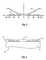
- phase profile of the representative lens 12a is a quantized approximation of the continuous phase profile of a theoretically ideal, 100% efficient, Fresnel zone plate. Accordingly, it will be evident that the acoustic focusing efficiency of the lens 12a and the width of its narrowest feature (i. e., its outermost phase step) are dependent upon the number, n, of discrete phase levels to which its phase profile is quantized.
- two phase, four phase, eight phase and sixteen phase embodiments are approximately 41%, 81%, 95%, and 99% efficient, respectively, for diffracting axial incident radiation into a focused + 1 diffraction order.
- the remainder of the incident energy is diffracted into the higher positive diffraction orders and into the negative diffraction orders, but virtually none of it is diffracted into the zeroth order.
- the two phase embodiment might be somewhat marginal for at least some acoustic ink printing applications, such as when the printing is performed using an array of lenses (a case in which the two phase embodiment might require relatively extraordinary provision for preventing undesirable levels of crosstalk between spatially adjacent lenses).
- the four, eight and sixteen phase embodiments progressively reduce the amount of energy that is diffracted into the unwanted, potentially troublesome orders by a cumulative factor of approximately 3X each, so they are preferred from an acoustics point of view.
- the lens 12a shown in Fig. 3 has four discrete phase levels because a four phase embodiment can be manufactured readily through the use of currently available semiconductor integrated circuit fabrication techniques.
- This particular lens is formed by patterning an ⁇ -Si layer 23 having a longitudinal sound velocity of approximately 8603 m/sec. to bring axially incident, plane wave acoustic radiation having a nominal frequency of 167MHz to focus in a + 1 diffraction order at a focal distance of 300 ⁇ m through an intermediate liquid layer having a longitudinal sound velocity of 1500 m/sec.
- the lens 12a is designed to have f/number of f/1.
- the radial phase profile of the lens 12a and the approximate relative phase advance, w k , associated with each of its phase steps are as set forth below (all dimensions are expressed in microns): where k k is a dimensionless phase step index; ⁇ k is the radial distance from the center of the aperture of the lens 12a to its k th phase transition; and h k is the height of the k th phase step of the lens 12a relative to the surface of the underlying substrate 22 (Fig. 2).
- k k is a dimensionless phase step index
- ⁇ k is the radial distance from the center of the aperture of the lens 12a to its k th phase transition
- h k is the height of the k th phase step of the lens 12a relative to the surface of the underlying substrate 22 (Fig. 2).
- the relative phase change of the + 1 diffraction order that is caused by these phase transitions is expressed as a relative "phase advance," W k , because the acoustic velocity of the wavefront of the radiation decreases as it propagates from the lens 12a into the ink 16 (Fig. 2).
- the lens 12a is designed so that its "phase delay" for the + 1 diffraction order decreases radially of its aperture as a function of approximately the square of the radial distance, ⁇ k , which means that the lens 12a simulates a concave refractive lens.
- the lenses 12a-12i are fabricated through the use of a conventional photolithographic patterning process for etching them into an acoustically flat layer 23 of etchable material, such as a-Si, which is grown or otherwise deposited on an acoustically flat face of an etch resistant substrate 22, such as a quartz or glass substrate.
- etchable material such as a-Si
- an etch resistant substrate 22 such as a quartz or glass substrate.
- the thickness of the ⁇ -Si layer 23 can be controlled with sufficient precision while it is being deposited to yield an acoustically flat layer of a-Si having a thickness essentially equal to the height of the highest phase steps of the lenses 12a-12i (i. e., a thickness of 2 ⁇ (n-1)/n radians), no further pre-etch processing is required. It sometimes may be easier, however, to first grow a somewhat thicker layer of a-Si on the substrate 22 and to thereafter polish that a-Si layer down to the thickness and acoustical flatness desired of the layer 23.
- etch steps are employed for etching the phase profiles of the lenses 12a-12i into the ⁇ -Si layer 23.
- the individual masks of a multi-mask mask set may be etched into the a-Si layer 23 in any desired order, but the depths to which the masks of a binary weighted mask set are etched into the a-Si layer 23 varies from mask-to-mask in dependence upon their respective binary weights.
- a mask aligner (not shown) should be used to register the successive mask patterns with the appropriate precision
- the ⁇ -Si layer 23 is overcoated with a conventional uv-sensitive photoresist 31 which then is exposed to uv radiation in accordance with the binary amplitude pattern of a first mask 32. Thereafter, the exposed photoresist 31 typically is removed from the ⁇ -Si layer 23, such as by a wet etch washing.
- An anisotropic etch such as a reactive ion etch, then is employed for removing material from the exposed regions of the ⁇ -Si layer 23 (i. e., the regions not overcoated with the unexposed photoresist 31) to a depth dependent upon the binary weight of the mask 32.
- An anisotropic etch is preferred because it creates phase steps having essentially vertical sidewalls, thereby producing sharp phase transitions between neighboring phase steps.
- the etch depth for a multi-mask set of binary weighted amplitude masks varies from mask-to-mask.
- the cumulative depth of all of the etches is: so the etch resistant substrate 22 is an effective etch-stop for the final etch.
- the focusing that is performed by the lenses 12a-12i is entirely diffractive.
- the lenses 12a-12i are shown as having generally flat geometries which are modulated by their phase profiles.
- Flat lens geometries are preferred for acoustic ink printers, such as the printer 13 (Fig. 2), in which the lenses 12a-12i are directly coupled to the ink 16 because it is relatively easy to maintain a smooth, uniform flow of ink across the output or radiating face of such a lens.
- flat lens geometries also are preferred for acoustic ink printheads, such as the printhead 35 of Fig.
- a thin, acoustically conductive, planarizing layer 37 composed, for example, of a polymer, such as polyimide or PMMA.
- the relatively flat geometry of the lens or lenses 36 makes it relatively easy to spin-coat or otherwise overcoat the printhead 35 with an essentially planar layer 37 of the selected acoustic coupling medium.
- an intermediate acoustic coupling medium such as the planarizing layer 37
- its longitudinal acoustic velocity should be taken into account while computing the lens phase profiles.
- the lens or lenses 36 are designed based on the same design parameters as set forth hereinabove with reference to the design of the lens 12a, in view of the additional assumption that they will be overcoated with a thin layer of polyimide (longitudinal acoustic velocity of 2300 m/sec.)
- each of the phase step heights given in the foregoing table should be increased by a factor of approximately 1.127.
- the corresponding factor for the PMMA planarized embodiment of the printhead 35 (assuming all other design parameters are the same) is about 1.203.
- the multi-discrete-phase Fresnel acoustic focusing lenses of this invention are well suited for acoustic ink printing and for other applications requiring economical acoustic focusing lenses complying with relatively exacting specifications, including specifications governing the relative spatial positioning of such lenses in integrated lens arrays.
- the relatively flat geometries of the acoustic focusing lenses provided by the preferred embodiments of this invention are advantageous for acoustic ink printers of various types, including those in which the lenses are acoustically coupled to the ink directly and those in which the lenses are indirectly acoustically coupled to the ink through an intermediate acoustic coupling medium, such as a printhead planarizing layer.
Landscapes
- Physics & Mathematics (AREA)
- Engineering & Computer Science (AREA)
- Acoustics & Sound (AREA)
- Multimedia (AREA)
- Particle Formation And Scattering Control In Inkjet Printers (AREA)
- Dot-Matrix Printers And Others (AREA)
- Transducers For Ultrasonic Waves (AREA)
Applications Claiming Priority (2)
| Application Number | Priority Date | Filing Date | Title |
|---|---|---|---|
| US07/456,409 US5041849A (en) | 1989-12-26 | 1989-12-26 | Multi-discrete-phase Fresnel acoustic lenses and their application to acoustic ink printing |
| US456409 | 1989-12-26 |
Publications (3)
| Publication Number | Publication Date |
|---|---|
| EP0434931A2 true EP0434931A2 (fr) | 1991-07-03 |
| EP0434931A3 EP0434931A3 (en) | 1992-08-26 |
| EP0434931B1 EP0434931B1 (fr) | 1997-02-19 |
Family
ID=23812640
Family Applications (1)
| Application Number | Title | Priority Date | Filing Date |
|---|---|---|---|
| EP90120920A Expired - Lifetime EP0434931B1 (fr) | 1989-12-26 | 1990-10-31 | Lentilles de Fresnel acoustiques multiples à phase discrète et leur application à l'impression acoustique à jet d'encre |
Country Status (4)
| Country | Link |
|---|---|
| US (1) | US5041849A (fr) |
| EP (1) | EP0434931B1 (fr) |
| JP (1) | JP2511570B2 (fr) |
| DE (1) | DE69029964T2 (fr) |
Cited By (12)
| Publication number | Priority date | Publication date | Assignee | Title |
|---|---|---|---|---|
| WO1994028540A3 (fr) * | 1993-06-01 | 1995-01-26 | Storz Medical Ag | Dispositif pour le traitement de tissus biologiques et de concretions corporelles |
| EP0739732A1 (fr) * | 1995-04-27 | 1996-10-30 | Xerox Corporation | Tête d'impression acoustique à encre avec distance focale variable |
| FR2736790A1 (fr) * | 1995-07-10 | 1997-01-17 | Intercontrole Sa | Traducteur ultrasonore comprenant un ensemble focalisant d'elements piezoelectriques et une lentille mince de focalisation |
| WO2002026394A1 (fr) * | 2000-09-25 | 2002-04-04 | Picoliter Inc. | Procede d'energie acoustique focalisee et dispositif de generation de gouttelettes de fluides non miscibles |
| WO2002071051A3 (fr) * | 2001-02-14 | 2003-01-09 | Picoliter Inc | Introduction d'un echantillon acoustique pour analyse et/ou traitement |
| US6548308B2 (en) | 2000-09-25 | 2003-04-15 | Picoliter Inc. | Focused acoustic energy method and device for generating droplets of immiscible fluids |
| US6603118B2 (en) | 2001-02-14 | 2003-08-05 | Picoliter Inc. | Acoustic sample introduction for mass spectrometric analysis |
| US6642061B2 (en) | 2000-09-25 | 2003-11-04 | Picoliter Inc. | Use of immiscible fluids in droplet ejection through application of focused acoustic energy |
| US6707038B2 (en) | 2001-02-14 | 2004-03-16 | Picoliter Inc. | Method and system using acoustic ejection for selective fluid deposition on a nonuniform sample surface |
| US6855925B2 (en) | 2001-02-14 | 2005-02-15 | Picoliter Inc. | Methods, devices, and systems using acoustic ejection for depositing fluid droplets on a sample surface for analysis |
| US6869551B2 (en) | 2001-03-30 | 2005-03-22 | Picoliter Inc. | Precipitation of solid particles from droplets formed using focused acoustic energy |
| WO2011131819A1 (fr) * | 2010-04-22 | 2011-10-27 | Consejo Superior De Investigaciones Científicas (Csic) | Lentille acoustique tridimensionnelle |
Families Citing this family (97)
| Publication number | Priority date | Publication date | Assignee | Title |
|---|---|---|---|---|
| JPH06160610A (ja) * | 1989-12-26 | 1994-06-07 | Xerox Corp | 不連続多位相フレネルレンズ製造方法 |
| US5450107A (en) * | 1991-12-27 | 1995-09-12 | Xerox Corporation | Surface ripple wave suppression by anti-reflection in apertured free ink surface level controllers for acoustic ink printers |
| US5339101A (en) * | 1991-12-30 | 1994-08-16 | Xerox Corporation | Acoustic ink printhead |
| US5354419A (en) * | 1992-08-07 | 1994-10-11 | Xerox Corporation | Anisotropically etched liquid level control structure |
| US5216451A (en) * | 1992-12-27 | 1993-06-01 | Xerox Corporation | Surface ripple wave diffusion in apertured free ink surface level controllers for acoustic ink printers |
| JPH07137250A (ja) * | 1993-05-14 | 1995-05-30 | Fujitsu Ltd | 超音波プリンタ |
| US5565113A (en) * | 1994-05-18 | 1996-10-15 | Xerox Corporation | Lithographically defined ejection units |
| EP0682988B1 (fr) * | 1994-05-18 | 2001-11-14 | Xerox Corporation | Déposition acoustique de couches de matériaux |
| EP0692383B1 (fr) * | 1994-07-11 | 2005-06-15 | Kabushiki Kaisha Toshiba | Dispositif d'enregistrement à jet d'encre |
| US5608433A (en) * | 1994-08-25 | 1997-03-04 | Xerox Corporation | Fluid application device and method of operation |
| US5488954A (en) * | 1994-09-09 | 1996-02-06 | Georgia Tech Research Corp. | Ultrasonic transducer and method for using same |
| US5631678A (en) * | 1994-12-05 | 1997-05-20 | Xerox Corporation | Acoustic printheads with optical alignment |
| US5821958A (en) * | 1995-11-13 | 1998-10-13 | Xerox Corporation | Acoustic ink printhead with variable size droplet ejection openings |
| EP0881082A3 (fr) | 1997-05-29 | 2000-05-03 | Xerox Corporation | Dispositif et procédé de formation d'images avec réduction des défauts d'impression |
| JP3438535B2 (ja) | 1997-06-23 | 2003-08-18 | 富士ゼロックス株式会社 | 記録ヘッド |
| US6019814A (en) * | 1997-11-25 | 2000-02-01 | Xerox Corporation | Method of manufacturing 3D parts using a sacrificial material |
| US6007183A (en) * | 1997-11-25 | 1999-12-28 | Xerox Corporation | Acoustic metal jet fabrication using an inert gas |
| US6644766B1 (en) | 1998-04-28 | 2003-11-11 | Xerox Corporation | Printing system with phase shift printing to reduce peak power consumption |
| US6210783B1 (en) | 1998-07-17 | 2001-04-03 | Xerox Corporation | Ink jet transparencies |
| US6312121B1 (en) | 1998-09-11 | 2001-11-06 | Xerox Corporation | Ink jet printing process |
| US6340216B1 (en) | 1998-09-30 | 2002-01-22 | Xerox Corporation | Ballistic aerosol marking apparatus for treating a substrate |
| US6416157B1 (en) | 1998-09-30 | 2002-07-09 | Xerox Corporation | Method of marking a substrate employing a ballistic aerosol marking apparatus |
| US6511149B1 (en) | 1998-09-30 | 2003-01-28 | Xerox Corporation | Ballistic aerosol marking apparatus for marking a substrate |
| US6290342B1 (en) | 1998-09-30 | 2001-09-18 | Xerox Corporation | Particulate marking material transport apparatus utilizing traveling electrostatic waves |
| US6416156B1 (en) | 1998-09-30 | 2002-07-09 | Xerox Corporation | Kinetic fusing of a marking material |
| US6523928B2 (en) | 1998-09-30 | 2003-02-25 | Xerox Corporation | Method of treating a substrate employing a ballistic aerosol marking apparatus |
| US6291088B1 (en) | 1998-09-30 | 2001-09-18 | Xerox Corporation | Inorganic overcoat for particulate transport electrode grid |
| US6751865B1 (en) | 1998-09-30 | 2004-06-22 | Xerox Corporation | Method of making a print head for use in a ballistic aerosol marking apparatus |
| US6454384B1 (en) | 1998-09-30 | 2002-09-24 | Xerox Corporation | Method for marking with a liquid material using a ballistic aerosol marking apparatus |
| US6265050B1 (en) | 1998-09-30 | 2001-07-24 | Xerox Corporation | Organic overcoat for electrode grid |
| US6467862B1 (en) | 1998-09-30 | 2002-10-22 | Xerox Corporation | Cartridge for use in a ballistic aerosol marking apparatus |
| US6136442A (en) * | 1998-09-30 | 2000-10-24 | Xerox Corporation | Multi-layer organic overcoat for particulate transport electrode grid |
| US6364454B1 (en) | 1998-09-30 | 2002-04-02 | Xerox Corporation | Acoustic ink printing method and system for improving uniformity by manipulating nonlinear characteristics in the system |
| US6302524B1 (en) * | 1998-10-13 | 2001-10-16 | Xerox Corporation | Liquid level control in an acoustic droplet emitter |
| US6136210A (en) * | 1998-11-02 | 2000-10-24 | Xerox Corporation | Photoetching of acoustic lenses for acoustic ink printing |
| US6187211B1 (en) * | 1998-12-15 | 2001-02-13 | Xerox Corporation | Method for fabrication of multi-step structures using embedded etch stop layers |
| US6416678B1 (en) * | 1998-12-22 | 2002-07-09 | Xerox Corporation | Solid bi-layer structures for use with high viscosity inks in acoustic ink printing and methods of fabrication |
| US6318852B1 (en) | 1998-12-30 | 2001-11-20 | Xerox Corporation | Color gamut extension of an ink composition |
| US6200491B1 (en) | 1999-03-23 | 2001-03-13 | Xerox Corporation | Fabrication process for acoustic lens array for use in ink printing |
| US6110265A (en) | 1999-04-27 | 2000-08-29 | Xerox Corporation | Ink compositions |
| US6595618B1 (en) | 1999-06-28 | 2003-07-22 | Xerox Corporation | Method and apparatus for filling and capping an acoustic ink printhead |
| US6523944B1 (en) | 1999-06-30 | 2003-02-25 | Xerox Corporation | Ink delivery system for acoustic ink printing applications |
| US6318831B1 (en) * | 1999-07-29 | 2001-11-20 | Xerox Corporation | Method and apparatus to provide adjustable excitement of a transducer in a printing system in order to compensate for different transducer efficiencies |
| US6293659B1 (en) | 1999-09-30 | 2001-09-25 | Xerox Corporation | Particulate source, circulation, and valving system for ballistic aerosol marking |
| US6328436B1 (en) | 1999-09-30 | 2001-12-11 | Xerox Corporation | Electro-static particulate source, circulation, and valving system for ballistic aerosol marking |
| US6494565B1 (en) | 1999-11-05 | 2002-12-17 | Xerox Corporation | Methods and apparatuses for operating a variable impedance acoustic ink printhead |
| US6322187B1 (en) | 2000-01-19 | 2001-11-27 | Xerox Corporation | Method for smoothing appearance of an ink jet print |
| US6350795B1 (en) | 2000-06-07 | 2002-02-26 | Xerox Corporation | Ink compositions |
| US6287373B1 (en) | 2000-06-22 | 2001-09-11 | Xerox Corporation | Ink compositions |
| US6461417B1 (en) | 2000-08-24 | 2002-10-08 | Xerox Corporation | Ink compositions |
| US6432184B1 (en) | 2000-08-24 | 2002-08-13 | Xerox Corporation | Ink compositions |
| US6746104B2 (en) * | 2000-09-25 | 2004-06-08 | Picoliter Inc. | Method for generating molecular arrays on porous surfaces |
| US7900505B2 (en) | 2000-09-25 | 2011-03-08 | Labcyte Inc. | Acoustic assessment of fluids in a plurality of reservoirs |
| US6666541B2 (en) * | 2000-09-25 | 2003-12-23 | Picoliter Inc. | Acoustic ejection of fluids from a plurality of reservoirs |
| US6808934B2 (en) | 2000-09-25 | 2004-10-26 | Picoliter Inc. | High-throughput biomolecular crystallization and biomolecular crystal screening |
| CA2423063C (fr) | 2000-09-25 | 2010-12-14 | Picoliter Inc. | Energie acoustique focalisee utilisee dans la preparation et le criblage de bibliotheques combinatoires |
| US20040119793A1 (en) * | 2000-09-25 | 2004-06-24 | Mutz Mitchell W. | Acoustic assessment of fluids in a plurality of reservoirs |
| JP4624644B2 (ja) | 2000-09-25 | 2011-02-02 | ピコリター インコーポレイテッド | 複数のリザブワーからの流体の音響出射 |
| US6543871B1 (en) | 2000-11-21 | 2003-04-08 | Electronics For Imaging, Inc. | Mask generator and image mask patterns |
| US6849423B2 (en) * | 2000-11-29 | 2005-02-01 | Picoliter Inc | Focused acoustics for detection and sorting of fluid volumes |
| US6893836B2 (en) * | 2000-11-29 | 2005-05-17 | Picoliter Inc. | Spatially directed ejection of cells from a carrier fluid |
| US20020064809A1 (en) | 2000-11-29 | 2002-05-30 | Mutz Mitchell W. | Focused acoustic ejection cell sorting system and method |
| US6596239B2 (en) * | 2000-12-12 | 2003-07-22 | Edc Biosystems, Inc. | Acoustically mediated fluid transfer methods and uses thereof |
| US6610223B2 (en) | 2001-03-30 | 2003-08-26 | Picoliter Inc. | Focused acoustic energy in the generation of solid particles |
| US6596206B2 (en) | 2001-03-30 | 2003-07-22 | Picoliter Inc. | Generation of pharmaceutical agent particles using focused acoustic energy |
| US6416164B1 (en) | 2001-07-20 | 2002-07-09 | Picoliter Inc. | Acoustic ejection of fluids using large F-number focusing elements |
| US6976639B2 (en) | 2001-10-29 | 2005-12-20 | Edc Biosystems, Inc. | Apparatus and method for droplet steering |
| US6737109B2 (en) | 2001-10-31 | 2004-05-18 | Xerox Corporation | Method of coating an ejector of an ink jet printhead |
| US6925856B1 (en) | 2001-11-07 | 2005-08-09 | Edc Biosystems, Inc. | Non-contact techniques for measuring viscosity and surface tension information of a liquid |
| US20030101819A1 (en) * | 2001-12-04 | 2003-06-05 | Mutz Mitchell W. | Acoustic assessment of fluids in a plurality of reservoirs |
| US7454958B2 (en) * | 2001-12-04 | 2008-11-25 | Labcyte Inc. | Acoustic determination of properties of reservoirs and of fluids contained therein |
| US7717544B2 (en) | 2004-10-01 | 2010-05-18 | Labcyte Inc. | Method for acoustically ejecting a droplet of fluid from a reservoir by an acoustic fluid ejection apparatus |
| US7354141B2 (en) * | 2001-12-04 | 2008-04-08 | Labcyte Inc. | Acoustic assessment of characteristics of a fluid relevant to acoustic ejection |
| US6893115B2 (en) | 2002-09-20 | 2005-05-17 | Picoliter Inc. | Frequency correction for drop size control |
| US7275807B2 (en) * | 2002-11-27 | 2007-10-02 | Edc Biosystems, Inc. | Wave guide with isolated coupling interface |
| US7429359B2 (en) * | 2002-12-19 | 2008-09-30 | Edc Biosystems, Inc. | Source and target management system for high throughput transfer of liquids |
| US7070260B2 (en) * | 2003-01-09 | 2006-07-04 | Labcyte Inc. | Droplet dispensation from a reservoir with reduction in uncontrolled electrostatic charge |
| US6969160B2 (en) * | 2003-07-28 | 2005-11-29 | Xerox Corporation | Ballistic aerosol marking apparatus |
| US7504446B2 (en) * | 2003-10-09 | 2009-03-17 | Xerox Corporation | Aqueous inks containing colored polymers |
| JP2005270929A (ja) * | 2004-03-26 | 2005-10-06 | Hosokawa Funtai Gijutsu Kenkyusho:Kk | 液滴配列方法および液滴配列装置 |
| US20060210443A1 (en) | 2005-03-14 | 2006-09-21 | Stearns Richard G | Avoidance of bouncing and splashing in droplet-based fluid transport |
| US7621624B2 (en) * | 2007-05-18 | 2009-11-24 | National Central University | High-efficient ultrasonic ink-jet head and fabrication method of for the same |
| EP2232572A4 (fr) * | 2007-12-07 | 2012-10-17 | Alion Inc | Impression acoustique focalisée de matières photovoltaïques orientées |
| US7753636B2 (en) * | 2008-03-25 | 2010-07-13 | Hennig Emmett D | Adjustable bale mover spikes |
| US8151645B2 (en) * | 2008-04-04 | 2012-04-10 | Microsoft Systems Inc. | Methods and apparatus for ultrasonic coupling using micro surface tension and capillary effects |
| WO2009146140A2 (fr) * | 2008-04-04 | 2009-12-03 | Microsonic Systems Inc. | Procédés et systèmes de formation de réseaux de lentilles de fresnel uniformes et à performances élevées pour une manipulation de liquide ultrasonore |
| WO2009124290A1 (fr) * | 2008-04-04 | 2009-10-08 | Microsonic Systems Inc. | Procédés et systèmes de couplage ultrasonique en utilisant la pression des rayons ultrasoniques |
| US20100184244A1 (en) * | 2009-01-20 | 2010-07-22 | SunPrint, Inc. | Systems and methods for depositing patterned materials for solar panel production |
| US10787670B2 (en) | 2016-09-15 | 2020-09-29 | Labcyte Inc. | High-efficiency transfection of biological cells using sonoporation |
| FR3062546B1 (fr) | 2017-02-01 | 2021-09-10 | Inst Vedecom | Structure de diffraction integree dans une carte de circuit imprime et procede de fabrication de celle-ci |
| RU181238U1 (ru) * | 2017-11-01 | 2018-07-06 | Федеральное государственное бюджетное образовательное учреждение высшего образования "Сибирский государственный университет геосистем и технологий" (СГУГиТ) | Печатающая головка для акустического принтера |
| AU2018374058A1 (en) | 2017-11-22 | 2020-06-18 | Dh Technologies Development Pte. Ltd. | System and method for the acoustic loading of an analytical instrument using a continuous flow sampling probe |
| US10871430B2 (en) | 2018-03-03 | 2020-12-22 | Labcyte Inc. | System and method for extracting a target moiety from a sample using acoustic droplet ejection |
| JP7231646B2 (ja) | 2018-03-30 | 2023-03-01 | ラブサイト インコーポレイテッド | 流体不透過性超音波トランスデューサ |
| RU2688949C1 (ru) | 2018-08-24 | 2019-05-23 | Самсунг Электроникс Ко., Лтд. | Антенна миллиметрового диапазона и способ управления антенной |
| EP4281752A1 (fr) | 2021-02-26 | 2023-11-29 | Labcyte Inc. | Systèmes et procédés de détection et de commande de gouttelettes chargées |
| US20260054262A1 (en) | 2022-08-24 | 2026-02-26 | Labcyte Inc. | Automatic trajectory correction methods and systems for acoustic generated drops |
Family Cites Families (6)
| Publication number | Priority date | Publication date | Assignee | Title |
|---|---|---|---|---|
| JPS5114241A (ja) * | 1974-07-25 | 1976-02-04 | Mitsubishi Electric Corp | Antenasochi |
| US4308547A (en) * | 1978-04-13 | 1981-12-29 | Recognition Equipment Incorporated | Liquid drop emitter |
| US4562900A (en) * | 1984-12-20 | 1986-01-07 | Varian Associates, Inc. | Lens system for acoustic transducer array |
| US4697195A (en) * | 1985-09-16 | 1987-09-29 | Xerox Corporation | Nozzleless liquid droplet ejectors |
| US4751529A (en) * | 1986-12-19 | 1988-06-14 | Xerox Corporation | Microlenses for acoustic printing |
| US4751530A (en) * | 1986-12-19 | 1988-06-14 | Xerox Corporation | Acoustic lens arrays for ink printing |
-
1989
- 1989-12-26 US US07/456,409 patent/US5041849A/en not_active Expired - Lifetime
-
1990
- 1990-10-31 DE DE69029964T patent/DE69029964T2/de not_active Expired - Fee Related
- 1990-10-31 EP EP90120920A patent/EP0434931B1/fr not_active Expired - Lifetime
- 1990-11-20 JP JP2315283A patent/JP2511570B2/ja not_active Expired - Fee Related
Cited By (18)
| Publication number | Priority date | Publication date | Assignee | Title |
|---|---|---|---|---|
| WO1994028540A3 (fr) * | 1993-06-01 | 1995-01-26 | Storz Medical Ag | Dispositif pour le traitement de tissus biologiques et de concretions corporelles |
| US5795311A (en) * | 1993-06-01 | 1998-08-18 | Storz Medical Ag | Apparatus for the treatment of biological tissue and corporal concretions |
| EP0739732A1 (fr) * | 1995-04-27 | 1996-10-30 | Xerox Corporation | Tête d'impression acoustique à encre avec distance focale variable |
| FR2736790A1 (fr) * | 1995-07-10 | 1997-01-17 | Intercontrole Sa | Traducteur ultrasonore comprenant un ensemble focalisant d'elements piezoelectriques et une lentille mince de focalisation |
| US6642061B2 (en) | 2000-09-25 | 2003-11-04 | Picoliter Inc. | Use of immiscible fluids in droplet ejection through application of focused acoustic energy |
| WO2002026394A1 (fr) * | 2000-09-25 | 2002-04-04 | Picoliter Inc. | Procede d'energie acoustique focalisee et dispositif de generation de gouttelettes de fluides non miscibles |
| US6548308B2 (en) | 2000-09-25 | 2003-04-15 | Picoliter Inc. | Focused acoustic energy method and device for generating droplets of immiscible fluids |
| US6809315B2 (en) | 2001-02-14 | 2004-10-26 | Picoliter Inc. | Method and system using acoustic ejection for preparing and analyzing a cellular sample surface |
| US6603118B2 (en) | 2001-02-14 | 2003-08-05 | Picoliter Inc. | Acoustic sample introduction for mass spectrometric analysis |
| US6707038B2 (en) | 2001-02-14 | 2004-03-16 | Picoliter Inc. | Method and system using acoustic ejection for selective fluid deposition on a nonuniform sample surface |
| US6710335B2 (en) | 2001-02-14 | 2004-03-23 | Picoliter Inc. | Acoustic sample introduction for analysis and/or processing |
| WO2002071051A3 (fr) * | 2001-02-14 | 2003-01-09 | Picoliter Inc | Introduction d'un echantillon acoustique pour analyse et/ou traitement |
| US6855925B2 (en) | 2001-02-14 | 2005-02-15 | Picoliter Inc. | Methods, devices, and systems using acoustic ejection for depositing fluid droplets on a sample surface for analysis |
| AU2002240423B2 (en) * | 2001-02-14 | 2006-03-09 | Picoliter Inc. | Acoustic sample introduction for analysis and/or processing |
| US7405395B2 (en) | 2001-02-14 | 2008-07-29 | Picoliter, Inc. | Acoustic ejection into small openings |
| US6869551B2 (en) | 2001-03-30 | 2005-03-22 | Picoliter Inc. | Precipitation of solid particles from droplets formed using focused acoustic energy |
| WO2011131819A1 (fr) * | 2010-04-22 | 2011-10-27 | Consejo Superior De Investigaciones Científicas (Csic) | Lentille acoustique tridimensionnelle |
| ES2367641A1 (es) * | 2010-04-22 | 2011-11-07 | Consejo Superior De Investigaciones Científicas (Csic) | Lente acústica tridimensional. |
Also Published As
| Publication number | Publication date |
|---|---|
| EP0434931B1 (fr) | 1997-02-19 |
| DE69029964T2 (de) | 1997-05-28 |
| JPH03200199A (ja) | 1991-09-02 |
| DE69029964D1 (de) | 1997-03-27 |
| EP0434931A3 (en) | 1992-08-26 |
| JP2511570B2 (ja) | 1996-06-26 |
| US5041849A (en) | 1991-08-20 |
Similar Documents
| Publication | Publication Date | Title |
|---|---|---|
| US5041849A (en) | Multi-discrete-phase Fresnel acoustic lenses and their application to acoustic ink printing | |
| CA1292384C (fr) | Reseaux de lentilles acoustiques pour l'impression a l'encre | |
| US5111220A (en) | Fabrication of integrated acoustic ink printhead with liquid level control and device thereof | |
| CA1292386C (fr) | Microlentilles pour l'impression acoustique | |
| US5121141A (en) | Acoustic ink printhead with integrated liquid level control layer | |
| US6039425A (en) | Ink jet recording method and head | |
| EP1476782B1 (fr) | Matière de contrôle de la lumiere permettant l'affichage de couleur, d'information et d'images | |
| EP0636479B1 (fr) | Structure de recouvrement pour éjecteurs de gouttelettes | |
| US5392064A (en) | Liquid level control structure | |
| US5450107A (en) | Surface ripple wave suppression by anti-reflection in apertured free ink surface level controllers for acoustic ink printers | |
| JPH0635177B2 (ja) | 音響印刷用プリントヘッド | |
| US5354419A (en) | Anisotropically etched liquid level control structure | |
| EP0683405A1 (fr) | Fabrication acoustique de filtres colorés | |
| US5237343A (en) | Ink jet head substrate, ink jet head having same and manufacturing method for ink jet head | |
| EP0739732B1 (fr) | Tête d'impression acoustique à encre avec distance focale variable | |
| JPH0538809A (ja) | インクジエツトヘツド | |
| EP0272092B1 (fr) | Imprimantes acoustiques | |
| JPH0367659A (ja) | インクジェット記録装置 | |
| JPH03158242A (ja) | インクジェットプリンターヘッド | |
| JPS60117210A (ja) | 空間光変調器 | |
| JP2003090910A (ja) | カラーフィルタの製造方法および該方法に用いる微小液滴吐出装置 | |
| JPH06143561A (ja) | インクジェットヘッド | |
| JP2002316409A (ja) | 音響波集束体および音響インクジェット記録装置 | |
| JPH02208054A (ja) | 液体噴射記録装置 |
Legal Events
| Date | Code | Title | Description |
|---|---|---|---|
| PUAI | Public reference made under article 153(3) epc to a published international application that has entered the european phase |
Free format text: ORIGINAL CODE: 0009012 |
|
| AK | Designated contracting states |
Kind code of ref document: A2 Designated state(s): DE FR GB |
|
| PUAL | Search report despatched |
Free format text: ORIGINAL CODE: 0009013 |
|
| AK | Designated contracting states |
Kind code of ref document: A3 Designated state(s): DE FR GB |
|
| 17P | Request for examination filed |
Effective date: 19930225 |
|
| 17Q | First examination report despatched |
Effective date: 19940929 |
|
| GRAH | Despatch of communication of intention to grant a patent |
Free format text: ORIGINAL CODE: EPIDOS IGRA |
|
| GRAH | Despatch of communication of intention to grant a patent |
Free format text: ORIGINAL CODE: EPIDOS IGRA |
|
| GRAA | (expected) grant |
Free format text: ORIGINAL CODE: 0009210 |
|
| AK | Designated contracting states |
Kind code of ref document: B1 Designated state(s): DE FR GB |
|
| REF | Corresponds to: |
Ref document number: 69029964 Country of ref document: DE Date of ref document: 19970327 |
|
| ET | Fr: translation filed | ||
| PLBE | No opposition filed within time limit |
Free format text: ORIGINAL CODE: 0009261 |
|
| STAA | Information on the status of an ep patent application or granted ep patent |
Free format text: STATUS: NO OPPOSITION FILED WITHIN TIME LIMIT |
|
| 26N | No opposition filed | ||
| REG | Reference to a national code |
Ref country code: GB Ref legal event code: IF02 |
|
| PGFP | Annual fee paid to national office [announced via postgrant information from national office to epo] |
Ref country code: DE Payment date: 20071025 Year of fee payment: 18 |
|
| PGFP | Annual fee paid to national office [announced via postgrant information from national office to epo] |
Ref country code: GB Payment date: 20071031 Year of fee payment: 18 Ref country code: FR Payment date: 20071009 Year of fee payment: 18 |
|
| GBPC | Gb: european patent ceased through non-payment of renewal fee |
Effective date: 20081031 |
|
| REG | Reference to a national code |
Ref country code: FR Ref legal event code: ST Effective date: 20090630 |
|
| PG25 | Lapsed in a contracting state [announced via postgrant information from national office to epo] |
Ref country code: DE Free format text: LAPSE BECAUSE OF NON-PAYMENT OF DUE FEES Effective date: 20090501 |
|
| PG25 | Lapsed in a contracting state [announced via postgrant information from national office to epo] |
Ref country code: FR Free format text: LAPSE BECAUSE OF NON-PAYMENT OF DUE FEES Effective date: 20081031 |
|
| PG25 | Lapsed in a contracting state [announced via postgrant information from national office to epo] |
Ref country code: GB Free format text: LAPSE BECAUSE OF NON-PAYMENT OF DUE FEES Effective date: 20081031 |