EP0434974A1 - Carte avec une partie estampée et sa méthode de fabrication - Google Patents
Carte avec une partie estampée et sa méthode de fabrication Download PDFInfo
- Publication number
- EP0434974A1 EP0434974A1 EP90122205A EP90122205A EP0434974A1 EP 0434974 A1 EP0434974 A1 EP 0434974A1 EP 90122205 A EP90122205 A EP 90122205A EP 90122205 A EP90122205 A EP 90122205A EP 0434974 A1 EP0434974 A1 EP 0434974A1
- Authority
- EP
- European Patent Office
- Prior art keywords
- card
- emboss
- resin layer
- emboss portion
- resin
- Prior art date
- Legal status (The legal status is an assumption and is not a legal conclusion. Google has not performed a legal analysis and makes no representation as to the accuracy of the status listed.)
- Withdrawn
Links
Images


Classifications
-
- B—PERFORMING OPERATIONS; TRANSPORTING
- B42—BOOKBINDING; ALBUMS; FILES; SPECIAL PRINTED MATTER
- B42D—BOOKS; BOOK COVERS; LOOSE LEAVES; PRINTED MATTER CHARACTERISED BY IDENTIFICATION OR SECURITY FEATURES; PRINTED MATTER OF SPECIAL FORMAT OR STYLE NOT OTHERWISE PROVIDED FOR; DEVICES FOR USE THEREWITH AND NOT OTHERWISE PROVIDED FOR; MOVABLE-STRIP WRITING OR READING APPARATUS
- B42D25/00—Information-bearing cards or sheet-like structures characterised by identification or security features; Manufacture thereof
- B42D25/40—Manufacture
- B42D25/405—Marking
- B42D25/415—Marking using chemicals
- B42D25/42—Marking using chemicals by photographic processes
-
- B—PERFORMING OPERATIONS; TRANSPORTING
- B42—BOOKBINDING; ALBUMS; FILES; SPECIAL PRINTED MATTER
- B42D—BOOKS; BOOK COVERS; LOOSE LEAVES; PRINTED MATTER CHARACTERISED BY IDENTIFICATION OR SECURITY FEATURES; PRINTED MATTER OF SPECIAL FORMAT OR STYLE NOT OTHERWISE PROVIDED FOR; DEVICES FOR USE THEREWITH AND NOT OTHERWISE PROVIDED FOR; MOVABLE-STRIP WRITING OR READING APPARATUS
- B42D25/00—Information-bearing cards or sheet-like structures characterised by identification or security features; Manufacture thereof
- B42D25/30—Identification or security features, e.g. for preventing forgery
- B42D25/324—Reliefs
-
- B—PERFORMING OPERATIONS; TRANSPORTING
- B42—BOOKBINDING; ALBUMS; FILES; SPECIAL PRINTED MATTER
- B42D—BOOKS; BOOK COVERS; LOOSE LEAVES; PRINTED MATTER CHARACTERISED BY IDENTIFICATION OR SECURITY FEATURES; PRINTED MATTER OF SPECIAL FORMAT OR STYLE NOT OTHERWISE PROVIDED FOR; DEVICES FOR USE THEREWITH AND NOT OTHERWISE PROVIDED FOR; MOVABLE-STRIP WRITING OR READING APPARATUS
- B42D25/00—Information-bearing cards or sheet-like structures characterised by identification or security features; Manufacture thereof
- B42D25/40—Manufacture
- B42D25/405—Marking
- B42D25/425—Marking by deformation, e.g. embossing
-
- B—PERFORMING OPERATIONS; TRANSPORTING
- B42—BOOKBINDING; ALBUMS; FILES; SPECIAL PRINTED MATTER
- B42D—BOOKS; BOOK COVERS; LOOSE LEAVES; PRINTED MATTER CHARACTERISED BY IDENTIFICATION OR SECURITY FEATURES; PRINTED MATTER OF SPECIAL FORMAT OR STYLE NOT OTHERWISE PROVIDED FOR; DEVICES FOR USE THEREWITH AND NOT OTHERWISE PROVIDED FOR; MOVABLE-STRIP WRITING OR READING APPARATUS
- B42D25/00—Information-bearing cards or sheet-like structures characterised by identification or security features; Manufacture thereof
- B42D25/40—Manufacture
- B42D25/45—Associating two or more layers
- B42D25/465—Associating two or more layers using chemicals or adhesives
- B42D25/47—Associating two or more layers using chemicals or adhesives using adhesives
-
- G—PHYSICS
- G06—COMPUTING OR CALCULATING; COUNTING
- G06K—GRAPHICAL DATA READING; PRESENTATION OF DATA; RECORD CARRIERS; HANDLING RECORD CARRIERS
- G06K19/00—Record carriers for use with machines and with at least a part designed to carry digital markings
- G06K19/06—Record carriers for use with machines and with at least a part designed to carry digital markings characterised by the kind of the digital marking, e.g. shape, nature, code
- G06K19/06009—Record carriers for use with machines and with at least a part designed to carry digital markings characterised by the kind of the digital marking, e.g. shape, nature, code with optically detectable marking
- G06K19/06046—Constructional details
-
- G—PHYSICS
- G06—COMPUTING OR CALCULATING; COUNTING
- G06K—GRAPHICAL DATA READING; PRESENTATION OF DATA; RECORD CARRIERS; HANDLING RECORD CARRIERS
- G06K19/00—Record carriers for use with machines and with at least a part designed to carry digital markings
- G06K19/06—Record carriers for use with machines and with at least a part designed to carry digital markings characterised by the kind of the digital marking, e.g. shape, nature, code
- G06K19/067—Record carriers with conductive marks, printed circuits or semiconductor circuit elements, e.g. credit or identity cards also with resonating or responding marks without active components
- G06K19/07—Record carriers with conductive marks, printed circuits or semiconductor circuit elements, e.g. credit or identity cards also with resonating or responding marks without active components with integrated circuit chips
- G06K19/077—Constructional details, e.g. mounting of circuits in the carrier
- G06K19/07701—Constructional details, e.g. mounting of circuits in the carrier the record carrier comprising an interface suitable for human interaction
- G06K19/07703—Constructional details, e.g. mounting of circuits in the carrier the record carrier comprising an interface suitable for human interaction the interface being visual
Definitions
- the present invention relates to a card having an emboss portion such as an IC card and a magnetic card, and the like, and its manufacturing method.
- an IC card which has a liquid crystal display and a keyboard, and which can be used in not only an on-line state but also an off-line state, as a multifunction card.
- Such an IC card has a card base made of, for example, plastic material, in which a semiconductor chip constituting a microcomputer and a memory, and the like is embedded, inside a pocket-sized metallic panel.
- a card base made of, for example, plastic material, in which a semiconductor chip constituting a microcomputer and a memory, and the like is embedded, inside a pocket-sized metallic panel.
- a plurality of external terminals for data transmission or reception to or from an external device and for a power supply input.
- a keyboard and a liquid crystal display are incorporated. Then, the microcomputer is operated in an manual manner (off-line state) without using a reader/writer, thereby confirming the content of the memory.
- a magnetic strip storing magnetic data in the front surface, and an emboss character (embossing pattern) showing a name of the card owner and a registration number.
- the emboss character in the IC card is formed of a transparent photosensitive resin layer 2, which is formed on the surface of a card 1, and a colored thin film layer 3, which is formed on the surface of the photosensitive resin layer 2.
- a method in which a mask is used and resin is cast in the mask since it is difficult to form the thickness the resin layer 2 uniform, only resin is hardened in a practical use, thereafter, the thickness of the resin layer is made to be uniform by cutting and the colored resin is printed thereon, thereby forming the thin film layer 3.
- the thin film layer 3 forming of the colored resin of the emboss character is extremely thin, the color fades while the card is being used, thereby makes it difficult to read the emboss character.
- An object of the present invention is to provide a card having an emboss portion, which can easily read an embossing pattern even if the head of the embossing pattern is a little cut out and its entire height is reduced during the use of the card, and its manufacturing method.
- the card having an emboss portion comprises a card body, and an emboss portion formed on said card body, said emboss portion having a transparent first resin layer and a colored second resin layer formed on the first resin layer, wherein an embossing pattern having said two resin layers is formed by cutting said emboss portion into a desired pattern, has said two resin layers.
- the method for manufacturing the card having an emboss portion comprises the steps of: forming a transparent resin layer on an emboss portion of a card body; forming a colored resin layer on said transparent resin layer; and forming a desired embossing pattern by cutting said two layers of said emboss portion.
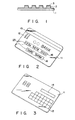
- Fig. 1 is a cross sectional view showing an embossing pattern in a conventional IC card
- Fig. 2 is a perspective view showing a front surface of an IC card according to an embodiment of the present invention
- Fig. 3 is a perspective view showing a rear surface of Fig. 2.
- Fig. 4 is an enlarged perspective view showing an emboss character forming portion of the IC card according to the embodiment of the present invention.
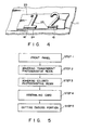
- Fig. 5 is a flow chart explaining a manufacturing process of the emboss character
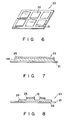
- Fig. 6 is a view showing a front panel of the IC card relating to the embodiment of the present invention.
- Fig. 7 is a side cross sectional view showing the emboss portion of the IC card according to the embodiment of the present invention.
- Fig. 8 is a side cross sectional view showing the emboss character
- Fig. 9 is an exploded view explaining the structure of the IC card according to the embodiment of the present invention.
- Fig. 10 is a view showing the inner structure of the IC card seen from the front side according to the embodiment of the present invention.
- Fig. 11 is a front view showing a cutting device for forming the emboss character.
- Fig. 12 is a side view of the cutting device.
- Figs. 2 and 3 are views showing an IC card as an example of a card having an emboss portion according to the present invention.
- Fig. 2 shows the front surface
- Fig. 3 shows the rear surface of the IC card.
- An IC card 11 has a card base formed of, for example, plastic material inside a pocket-sided metallic panel.
- a semiconductor chip such as a microcomputer and a memory, and the like is embedded.
- a plurality of external terminals 12 for data transmission or reception to or from an external device and for a power supply input.
- a keyboard 13 and a liquid crystal display window 14 are incorporated. Then, the microcomputer is operated in an manual manner (off-line state) without using a reader/writer, thereby confirming the content of storage. In other words, this card can be used as the so-called multifunction card.
- a magnetic stripe 15 storing magnetic data in the front surface
- an emboss character (embossing pattern) 16 showing a name of the card owner.
- the emboss character 16 includes a convex character, a number, and a mark formed by cutting an emboss portion 23 explained later.
- the emboss character 16 is normally recorded in the card 11 every owner after the card 11 is assembled.
- Fig. 4 is an enlarged view showing a portion in which the emboss character 16 of the card is formed.
- the emboss character 16 is formed in the emboss portion 23, and has a two-layered structure in which a transparent resin layer 24 and a colored resin layer 25 are stacked. These resin layers 24 and 25 are formed of, for example, photosensitive resin. In such a two-layered structure, the resin layer 25 can be formed to have a certain degree of thickness. For this reason, the character color can be clearly embossed. Moreover, even if pressure is applied on the surface of the character by an imprinter and the surface is rubbed, the color does not fade and the emboss character 16 can be easily read for a long time.
- this process comprises STEPS 1 to 5.
- a front panel which is a structural portion of IC card is formed (STEP 1).
- a front panel 20 is formed by providing a predetermined design print to a front panel substrate 21 made of stainless.
- transparent photosensitive resin is printed on the front panel 20 by, for example, a screen print, and is adhered and hardened, so that a first resin layer 24 is formed.
- a module for an IC card such as a semi-conductor chip and other parts are stacked on the front panel 20, and the IC card is stacked.
- the assembly of the IC card will be explained later.
- the emboss portion 23 is cut in accordance with data of the person to be a card owner and the emboss character 16 is formed as shown in Fig. 8.
- STEP 5 is performed by a card maker based on data which is supplied from a publisher.
- the card maker and the publisher may be the same.
- the emboss character 16 is formed in such a manner that the emboss character 16 is cut as a part of the transparent photosensitive resin layer 24 is left.
- the emboss character 16 is cut as a part of the transparent photosensitive resin layer 24 is left, strength of adhesion is increased and the emboss character cannot be easily peeled from the card as compared with the case in which the emboss character itself is formed on the card.
- the resin layer 24 is transparent, designs of banks or credit companies, which are printed in the front panel 21, are not damaged.
- two-layered structure having resin layers 24 and 25 is formed, the emboss character is not easily peeled from the card as compared with the case, in which a metal foil is thermally adhered, and such the emboss character can be easily seen.
- Fig. 9 is an exploded view explaining the structure of the IC card.
- reference numeral 30 is a back panel.
- a display window 14 In the back panel 30, there are provided a display window 14, a keyboard 4, and an opening 17 which is formed to project a contact 21 (explained later).
- a contact 21 Explained later.
- the balance at the bank, the term of validity, and data on the transaction up to the present are displayed.
- reference numeral 40 is a spacer.
- the spacer 40 there is provided an opening 41 corresponding to the display window 14.
- an opening 43 which is communicated with a number of openings 42, through which the keys of the keyboard 13 are inserted, and the opening 17 of the back panel 30.
- Reference numeral 50 is a membrane switch, which is turned on or off by the operation of the keyboard 13.
- Reference numeral 60 is a flexible printed circuit board (FPC).
- FPC flexible printed circuit board
- a main printed wiring board (TAB substrate) 61 and a battery 62 are connected to the FPC 60.
- a liquid crystal display (LDC) 63 and the membrane 50 are connected to the main printed wiring board 61.
- the liquid crystal display corresponds to the display window 14.
- Reference numeral 70 is a plastic dam which is injection-molded.
- the plastic dam constitutes the outer periphery of the IC card. Then, the above-mentioned front panel 20 is overlay on the plastic dam 70.
- an integrated circuit chip 64 constituting the IC card which has a multifunction such as a function as calculator, a function as a watch, and the like, and a driver 65 of the liquid crystal display 63 are mounted on the main printed board 61 by TAB connection.
- the integrated circuit chip 64 has a CPU and a memory.
- Fig. 10 is a view showing the inner structure of the IC card seen from the side of the front panel 20.
- a C-NET 66 In the printed circuit board 60, there are provided a C-NET 66, a crystal oscillator (electronic parts) 67, and a chip condenser 68.
- a contact 71 and withstand electrostatic element 72 are provided in the printed circuit board 60.
- the contact 71 is projected to the surface of the back panel 30 through the opening 43 of the spacer 40 and the opening 17 of the back panel 30.
- the contact 71 is connected to the terminal inside the external device when the IC card is inserted into the external device.
- the IC card 11 is fixed onto a table 81 as the emboss portion 23 is placed as a upper surface.
- the table 81 can be moved by a motor (not shown) in an illustrated X-axis direction to a main body 82, and also supported on a moving table 83 which can be moved in an illustrated Y-axis direction. Thereby, the table 81 can be moved in both X and Y-axis directions.
- a moving table 84 is supported to be movable in an illustrated Z-axis direction.
- a spindle 85 is rotatably supported in the moving table 84.
- the driving force of a motor 87 is transmitted to the spindle 85 via a repeater 86.
- a drill 88 is fixed to the end portion of the spindle 85 and the emboss portion 23 on the card 11 is cut by the drill 88.
- the movement of the table 81 in the X and Y-axes directions and that of the drill 88 in the Z-axis direction can be controlled, thereby the emboss portion 23 is arbitrarily cut and a desired emboss character (embossing pattern) can be formed.
- the cutting of such emboss portion 23 is controlled by an input controller 89 provided in the main body 82.
- the input controller 89 comprises a keyboard 90 for inputting data (data of emboss character 16 to be cut) and a display 91 for displaying data, and a controller 92.
- the controller 92 stores the position of the emboss portion 23 on the card 11, and calculates a character pattern to be formed, a cutting position, a depth of cutting based on the stored contents. Moreover, the controller 92 controls the movement of the table 81 in the X and Y-axes directions and that of the drill 88 in the Z-axis direction, and the rotation of the spindle 85 based on the calculated result.
- the emboss character formed by the above-mentioned device has the two-layered structure having the transparent resin layer and the colored resin layer.
- the colored portion of the emboss character can be formed to have a certain degree of thickness. Therefore, even if the surface of the emboss character is cut a little during the use of IC card, the color does not fade and the emboss character can be easily read for a long time.
- the emboss character is cut as mentioned above, the emboss character can be formed without giving mechanical and thermal shock to the card, and the height of the emboss character can be substantially uniform.
- the emboss character formed by the above-mentioned cutting has substantially the same physical characteristic as plastic material constituting the card material such as vinyl chloride. Due to this, such the emboss character is the substantially the same as an emboss character formed by pressing in terms of its appearance and strength.
- the emboss portion is formed by screen print.
- the present invention is not limited to this manner. For example, the following manner may be performed.
- a frame is mounted on the card and transparent resin is cast therein. Then, transparent resin is hardened, thereafter a roller containing colored resin is rotated on the resin layer. Thereby, the colored resin is transferred.
- the present invention is not limited to the two-layered structure. It is possible to form the structure in which three or more resin layers are overlay.
- the above embodiment explained the case in which IC card is used.
- the present invention can be applied to the case in which a card having the other emboss portion such as a magnetic card is used.
Landscapes
- Engineering & Computer Science (AREA)
- Manufacturing & Machinery (AREA)
- Theoretical Computer Science (AREA)
- Physics & Mathematics (AREA)
- General Physics & Mathematics (AREA)
- General Chemical & Material Sciences (AREA)
- Chemical Kinetics & Catalysis (AREA)
- Computer Hardware Design (AREA)
- Microelectronics & Electronic Packaging (AREA)
- Chemical & Material Sciences (AREA)
- Health & Medical Sciences (AREA)
- General Health & Medical Sciences (AREA)
- Toxicology (AREA)
- Credit Cards Or The Like (AREA)
Applications Claiming Priority (2)
| Application Number | Priority Date | Filing Date | Title |
|---|---|---|---|
| JP309134/89 | 1989-11-30 | ||
| JP1309134A JPH03169690A (ja) | 1989-11-30 | 1989-11-30 | 携帯可能媒体 |
Publications (1)
| Publication Number | Publication Date |
|---|---|
| EP0434974A1 true EP0434974A1 (fr) | 1991-07-03 |
Family
ID=17989307
Family Applications (1)
| Application Number | Title | Priority Date | Filing Date |
|---|---|---|---|
| EP90122205A Withdrawn EP0434974A1 (fr) | 1989-11-30 | 1990-11-20 | Carte avec une partie estampée et sa méthode de fabrication |
Country Status (2)
| Country | Link |
|---|---|
| EP (1) | EP0434974A1 (fr) |
| JP (1) | JPH03169690A (fr) |
Families Citing this family (1)
| Publication number | Priority date | Publication date | Assignee | Title |
|---|---|---|---|---|
| JP5141260B2 (ja) * | 2008-01-15 | 2013-02-13 | 大日本印刷株式会社 | エンボス文字形成用積層カード |
Citations (1)
| Publication number | Priority date | Publication date | Assignee | Title |
|---|---|---|---|---|
| DE3801563A1 (de) * | 1987-01-20 | 1988-07-28 | Toshiba Kawasaki Kk | Verfahren und vorrichtung zur herstellung eines praegemusters in einem tragbaren medium |
-
1989
- 1989-11-30 JP JP1309134A patent/JPH03169690A/ja active Pending
-
1990
- 1990-11-20 EP EP90122205A patent/EP0434974A1/fr not_active Withdrawn
Patent Citations (1)
| Publication number | Priority date | Publication date | Assignee | Title |
|---|---|---|---|---|
| DE3801563A1 (de) * | 1987-01-20 | 1988-07-28 | Toshiba Kawasaki Kk | Verfahren und vorrichtung zur herstellung eines praegemusters in einem tragbaren medium |
Non-Patent Citations (2)
| Title |
|---|
| PATENT ABSTRACTS OF JAPAN vol. 13, no. 477 (M-885), 27 October 1989; & JP - A - 1188250 (TOSHIBA CORP.) 27.07.1989 * |
| PATENT ABSTRACTS OF JAPAN vol. 13, no. 535 (M-899), 29 November 1989; & JP - A - 1218892 (TOSHIBA CORP.) 01.09.1989 * |
Also Published As
| Publication number | Publication date |
|---|---|
| JPH03169690A (ja) | 1991-07-23 |
Similar Documents
| Publication | Publication Date | Title |
|---|---|---|
| US4918631A (en) | Compact type electronic information card | |
| US4876441A (en) | Card-like electronic apparatus | |
| JP5418696B2 (ja) | 電子部品内蔵カード | |
| KR101760675B1 (ko) | 미들 패드를 포함하는 스마트 카드 및 그 제조 방법 | |
| US5504688A (en) | Compact disc marking method and apparatus | |
| JPH0452575B2 (fr) | ||
| JPS58501216A (ja) | 識別印付き部材の製造装置 | |
| JPS58219661A (ja) | カ−ド電卓 | |
| US6392881B1 (en) | Portable electronic device | |
| EP0434974A1 (fr) | Carte avec une partie estampée et sa méthode de fabrication | |
| JP2523354B2 (ja) | 計器用筺体および筺体収納用プログラムカ―ド | |
| JPH0512825Y2 (fr) | ||
| JPH08197878A (ja) | Icカード | |
| CN115210711A (zh) | 用于智能卡的预包装、智能卡及形成用于智能卡的预包装的方法 | |
| KR910007038B1 (ko) | 전자카드 | |
| JPH0811473B2 (ja) | 携帯可能媒体におけるエンボス状パタ−ンの作製方法 | |
| JPH0811472B2 (ja) | 携帯可能媒体におけるエンボス状パターンの作製装置 | |
| JPH0628305Y2 (ja) | 電子カ−ド | |
| JP2002108226A (ja) | 電子機器表示窓の保護パネル及びその製造方法 | |
| JPS63178091A (ja) | 携帯可能媒体におけるエンボス状パタ−ンの作製方法 | |
| JPH0628306Y2 (ja) | 電子カ−ド | |
| JPS6134664A (ja) | 電子機器 | |
| JP3074331B2 (ja) | 自動販売機展示用商品表示板 | |
| KR100820317B1 (ko) | 디스플레이 기능을 갖는 스마트 카드 | |
| JPS62271165A (ja) | 小型電子機器 |
Legal Events
| Date | Code | Title | Description |
|---|---|---|---|
| PUAI | Public reference made under article 153(3) epc to a published international application that has entered the european phase |
Free format text: ORIGINAL CODE: 0009012 |
|
| 17P | Request for examination filed |
Effective date: 19901217 |
|
| AK | Designated contracting states |
Kind code of ref document: A1 Designated state(s): DE FR GB |
|
| STAA | Information on the status of an ep patent application or granted ep patent |
Free format text: STATUS: THE APPLICATION HAS BEEN WITHDRAWN |
|
| 18W | Application withdrawn |
Withdrawal date: 19920710 |