EP0434980A2 - Dispositif de pulvérisation de matières fluides ou solides, de préférence de métaux fondus - Google Patents
Dispositif de pulvérisation de matières fluides ou solides, de préférence de métaux fondus Download PDFInfo
- Publication number
- EP0434980A2 EP0434980A2 EP90122347A EP90122347A EP0434980A2 EP 0434980 A2 EP0434980 A2 EP 0434980A2 EP 90122347 A EP90122347 A EP 90122347A EP 90122347 A EP90122347 A EP 90122347A EP 0434980 A2 EP0434980 A2 EP 0434980A2
- Authority
- EP
- European Patent Office
- Prior art keywords
- atomizing
- nozzles
- fluid
- jet
- fluid jet
- Prior art date
- Legal status (The legal status is an assumption and is not a legal conclusion. Google has not performed a legal analysis and makes no representation as to the accuracy of the status listed.)
- Granted
Links
Images

Classifications
-
- B—PERFORMING OPERATIONS; TRANSPORTING
- B22—CASTING; POWDER METALLURGY
- B22F—WORKING METALLIC POWDER; MANUFACTURE OF ARTICLES FROM METALLIC POWDER; MAKING METALLIC POWDER; APPARATUS OR DEVICES SPECIALLY ADAPTED FOR METALLIC POWDER
- B22F9/00—Making metallic powder or suspensions thereof
- B22F9/02—Making metallic powder or suspensions thereof using physical processes
- B22F9/06—Making metallic powder or suspensions thereof using physical processes starting from liquid material
- B22F9/08—Making metallic powder or suspensions thereof using physical processes starting from liquid material by casting, e.g. through sieves or in water, by atomising or spraying
- B22F9/082—Making metallic powder or suspensions thereof using physical processes starting from liquid material by casting, e.g. through sieves or in water, by atomising or spraying atomising using a fluid
-
- B—PERFORMING OPERATIONS; TRANSPORTING
- B05—SPRAYING OR ATOMISING IN GENERAL; APPLYING FLUENT MATERIALS TO SURFACES, IN GENERAL
- B05B—SPRAYING APPARATUS; ATOMISING APPARATUS; NOZZLES
- B05B17/00—Apparatus for spraying or atomising liquids or other fluent materials, not covered by the preceding groups
- B05B17/04—Apparatus for spraying or atomising liquids or other fluent materials, not covered by the preceding groups operating with special methods
- B05B17/06—Apparatus for spraying or atomising liquids or other fluent materials, not covered by the preceding groups operating with special methods using ultrasonic or other kinds of vibrations
- B05B17/0607—Apparatus for spraying or atomising liquids or other fluent materials, not covered by the preceding groups operating with special methods using ultrasonic or other kinds of vibrations generated by electrical means, e.g. piezoelectric transducers
- B05B17/0623—Apparatus for spraying or atomising liquids or other fluent materials, not covered by the preceding groups operating with special methods using ultrasonic or other kinds of vibrations generated by electrical means, e.g. piezoelectric transducers coupled with a vibrating horn
-
- B—PERFORMING OPERATIONS; TRANSPORTING
- B22—CASTING; POWDER METALLURGY
- B22F—WORKING METALLIC POWDER; MANUFACTURE OF ARTICLES FROM METALLIC POWDER; MAKING METALLIC POWDER; APPARATUS OR DEVICES SPECIALLY ADAPTED FOR METALLIC POWDER
- B22F9/00—Making metallic powder or suspensions thereof
- B22F9/02—Making metallic powder or suspensions thereof using physical processes
- B22F9/06—Making metallic powder or suspensions thereof using physical processes starting from liquid material
- B22F9/08—Making metallic powder or suspensions thereof using physical processes starting from liquid material by casting, e.g. through sieves or in water, by atomising or spraying
- B22F9/082—Making metallic powder or suspensions thereof using physical processes starting from liquid material by casting, e.g. through sieves or in water, by atomising or spraying atomising using a fluid
- B22F2009/088—Fluid nozzles, e.g. angle, distance
Definitions
- the invention relates to a device for atomizing at least one jet of a liquid or solid substance, preferably molten metal, according to the preamble of patent claim 1.
- the invention is based on a known device (EP-A1 0 308 933), in which the radiating sonotrode surfaces are arranged in the tapered section of a nozzle, through which an inert or reaction gas is introduced into the ultrasound field between the sonotrode surfaces. This gas flow promotes the atomization process and allows targeted particle transport out of the atomization area.
- the combustion air can be blown radially through slot or ring nozzles into the pressure bellies or nodes of the standing wave of an ultrasonic field which is generated between a sonotrode and a reflector.
- the invention has for its object to design the device of the type described in such a way that the atomization throughput is significantly increased and the atomization process can be better regulated.
- the atomizing fluid jet which is usually liquid
- the additional fluid which is usually gaseous
- the throughput of additional fluid through the nozzles can be set separately from the atomizing fluid.
- a plurality of atomizing and additional fluid jets are preferably introduced.
- the throughput of atomizing fluid should not exceed an upper limit, since the jet then breaks through in the atomizing area and reduces the atomizing power.
- additional fluid streams are introduced into the atomization areas in the pressure node simultaneously and in addition to the actual atomizing fluid jet, the atomizing fluid mass throughput can be increased significantly.
- Liquids in particular melts
- solid substances minerals, powders, foams
- Gas, steam, mist, liquid, powder or the like can be used as the additional fluid.
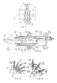
- FIG. 1 shows the device known from EP-A 0 308 933, in which an ultrasound standing field 3 with pressure nodes and pressure bellies is generated between two sonotrodes 1 and 2.
- the openings of melting crucibles 4 open into the node areas, from which one or more jets of melt emerge and are atomized in the ultrasound field of a gas passed between the sonotrode surfaces 5, 6.
- the sonotrode 2 belongs to an ultrasonic oscillator 10, which is shown in FIG. 2, which has a booster 11 and a converter 12.
- a housing 15 surrounding the converter 12 and the booster 11 is fastened in a pressure-tight manner.
- the housing 15 is arranged via a sleeve 17, which is also provided with seals 16, in an outer housing 18 which forms the passage through a wall 19 which separates the outer space 20 from the pressure space 21, in which the atomization is carried out.
- the cable 22 is introduced into the converter 12 via the housing 18.
- the housing 15 can be adjusted axially via an adjusting device 23.
- FIG. 3 shows an end view of the sonotrode surface 5 of the sonotrode 1.
- the atomizing fluid nozzles 25 there are several individual additional fluid nozzles 26 which are connected to pressure medium sources (not shown).
- the nozzles 25 and 26 are directed radially and offset on the circumference. Fluid flows are directed via the nozzles 25, 26 specifically onto the longitudinal axis 7 of the oscillator arrangement.
- the introduction into the pressure node areas of the ultrasound field is preferably carried out, as can also be seen from FIG. 5.
- the nozzles are arranged alternately, so that in addition to an atomizing fluid jet from the nozzle 25, an additional fluid jet emerges from the nozzle 26.
- FIG. 4 shows ring nozzles 28 in which the atomizing fluid jet emerges from a central opening 29 and the additional fluid jet emerges from an annular opening 30 which surrounds the central nozzle in an annular manner. All of these nozzles are each directed into a pressure node area of the standing wave.
- FIG. 5 shows the arrangement of several such individual or ring nozzles 25, 26, 28 shown in FIG. 3 or 4 for introducing atomizing and additional fluid flows into the individual pressure node areas of the standing shaft.
- a plurality of nozzles 25, 26, 28 are again provided for each pressure node area, as shown in FIG. 3 or 4.
- FIG. 6 shows a flat nozzle 35 with inlets 36 for atomizing fluid and inlets 37 for additional gas.
- the additional gas jet enters the atomizing area of the ultrasonic wave in a targeted manner on both sides of the atomizing gas jet emerging in the center.
- FIG. 7 shows the end view 5 of a rectangular sonotrode 1, for which the flat nozzle 35 is particularly suitable.
- the atomizing performance can also be increased with such a large-area sonotrode.
- FIG. 8 shows the arrangement in which a plurality of nozzles 25, 26 or ring nozzles 28 arranged in rows next to one another are provided in the ultrasound field generated by a large-area, rectangular sonotrode 1, each of which is arranged in the planes of the pressure node areas.
- FIG. 9 shows a further measure to improve the atomization performance.
- the sonotrode surfaces 5 and 6 are concave, so that the energy in the node of the ultrasonic standing wave is focused and thus the acoustic pressure is increased.
- the sonotrode radiation surfaces can also be coated in order to reduce wettability. This can be done, for example, by vapor deposition of boron nitrite, titanium nitrite or by chrome plating or anodizing, etc.
Landscapes
- Special Spraying Apparatus (AREA)
- Manufacture Of Metal Powder And Suspensions Thereof (AREA)
- Apparatuses For Generation Of Mechanical Vibrations (AREA)
- Coating By Spraying Or Casting (AREA)
Applications Claiming Priority (2)
| Application Number | Priority Date | Filing Date | Title |
|---|---|---|---|
| DE3993178 | 1989-11-27 | ||
| DE3939178A DE3939178A1 (de) | 1989-11-27 | 1989-11-27 | Vorrichtung zum zerstaeuben von fluessigen und festen stoffen, vorzugsweise geschmolzenen metalls |
Publications (3)
| Publication Number | Publication Date |
|---|---|
| EP0434980A2 true EP0434980A2 (fr) | 1991-07-03 |
| EP0434980A3 EP0434980A3 (en) | 1991-12-04 |
| EP0434980B1 EP0434980B1 (fr) | 1995-05-31 |
Family
ID=6394275
Family Applications (1)
| Application Number | Title | Priority Date | Filing Date |
|---|---|---|---|
| EP90122347A Expired - Lifetime EP0434980B1 (fr) | 1989-11-27 | 1990-11-22 | Dispositif de pulvérisation de matières fluides ou solides, de préférence de métaux fondus |
Country Status (5)
| Country | Link |
|---|---|
| US (1) | US5122047A (fr) |
| EP (1) | EP0434980B1 (fr) |
| JP (1) | JPH03242257A (fr) |
| AT (1) | ATE123239T1 (fr) |
| DE (2) | DE3939178A1 (fr) |
Cited By (2)
| Publication number | Priority date | Publication date | Assignee | Title |
|---|---|---|---|---|
| WO1993021353A1 (fr) * | 1992-04-10 | 1993-10-28 | Sprayforming Developments Limited | Moteur a anneau vibrant pour une alimentation en substances particulaires |
| EP4725624A1 (fr) | 2024-10-14 | 2026-04-15 | Amazemet Spolka Z Ograniczona Odpowiedzialnoscia | Procédé d'atomisation de charge d'alimentation en poudre et dispositif d'atomisation de charge d'alimentation en poudre |
Families Citing this family (11)
| Publication number | Priority date | Publication date | Assignee | Title |
|---|---|---|---|---|
| US5176874A (en) * | 1991-11-05 | 1993-01-05 | General Electric Company | Controlled process for the production of a spray of atomized metal droplets |
| US5794861A (en) * | 1995-10-05 | 1998-08-18 | D & R Recyclers, Inc. | Process and apparatus for separating components of fragmented vehicle tires |
| DE10245326A1 (de) * | 2002-09-27 | 2004-04-08 | Abb Patent Gmbh | Ultraschall-Stehwellen-Zerstäuberanordnung |
| DE10245324A1 (de) * | 2002-09-27 | 2004-04-08 | Abb Patent Gmbh | Ultraschall-Stehwellen-Zerstäuberanordnung |
| DE10252437A1 (de) * | 2002-11-12 | 2004-05-27 | Abb Patent Gmbh | Ultraschall-Stehwellen-Zerstäuberanordnung |
| JP2004290877A (ja) * | 2003-03-27 | 2004-10-21 | Toyota Motor Corp | 回転霧化塗装装置 |
| DE10327429A1 (de) * | 2003-06-18 | 2005-01-05 | Abb Patent Gmbh | Ultraschall-Stehwellen-Zerstäuberanordnung |
| DE10327430A1 (de) * | 2003-06-18 | 2005-01-05 | Abb Patent Gmbh | Ultraschall-Stehwellen-Zerstäuberanordnung |
| DE10327431A1 (de) * | 2003-06-18 | 2005-01-05 | Abb Patent Gmbh | Ultraschall-Stehwellen-Zerstäuberanordnung |
| US8893992B2 (en) * | 2012-04-19 | 2014-11-25 | General Electric Company | System and method for pulverizing a substance |
| CN109622980A (zh) * | 2019-01-28 | 2019-04-16 | 哈尔滨工业大学 | 一种熔融金属超声驻波非接触式雾化制粉装置及方法 |
Family Cites Families (11)
| Publication number | Priority date | Publication date | Assignee | Title |
|---|---|---|---|---|
| US3274642A (en) * | 1965-05-12 | 1966-09-27 | Armour & Co | Apparatus for prilling ammonium nitrate |
| GB1272229A (en) * | 1968-11-27 | 1972-04-26 | British Iron Steel Research | Improvements in and relating to the treatment of molten material |
| US4153201A (en) * | 1976-11-08 | 1979-05-08 | Sono-Tek Corporation | Transducer assembly, ultrasonic atomizer and fuel burner |
| DE2842232C2 (de) * | 1978-09-28 | 1985-04-18 | Battelle-Institut E.V., 6000 Frankfurt | Verfahren und Vorrichtung zum Zerstäuben von Flüssigkeiten, Suspensionen und Emulsionen, agglomerierten Stäuben bzw. Pulvern sowie Mischungen derselben |
| CA1159356A (fr) * | 1979-10-25 | 1983-12-27 | Kurt Skoog | Production de microgouttelettes de fluide |
| DE3108481A1 (de) * | 1980-04-17 | 1982-02-04 | Hauni-Werke Körber & Co KG, 2050 Hamburg | Vorrichtung zum auftragen von weichmacherfluessigkeit auf eine bewegte gewebebahn |
| DE3407059A1 (de) * | 1984-02-27 | 1985-08-29 | Siemens AG, 1000 Berlin und 8000 München | Verfahren zur herstellung reagierter rohstoffe fuer elektrokeramik |
| DE3713253A1 (de) * | 1986-07-23 | 1988-02-04 | Bosch Gmbh Robert | Ultraschallzerstaeuberanlage |
| DE3735787A1 (de) * | 1987-09-22 | 1989-03-30 | Stiftung Inst Fuer Werkstoffte | Verfahren und vorrichtung zum zerstaeuben mindestens eines strahls eines fluessigen stoffs, vorzugsweise geschmolzenen metalls |
| DE3732325A1 (de) * | 1987-09-25 | 1989-04-13 | Battelle Institut E V | Vorrichtung zum zerstaeuben eines fluessigen mediums mit hilfe von ultraschall |
| LU87346A1 (de) * | 1988-09-27 | 1990-04-06 | Euratom | Verfahren und vorrichtung zum herstellen eines pulvers aus amorpher keramischer oder metallischer substanz |
-
1989
- 1989-11-27 DE DE3939178A patent/DE3939178A1/de not_active Withdrawn
-
1990
- 1990-11-22 DE DE59009180T patent/DE59009180D1/de not_active Expired - Fee Related
- 1990-11-22 EP EP90122347A patent/EP0434980B1/fr not_active Expired - Lifetime
- 1990-11-22 AT AT90122347T patent/ATE123239T1/de not_active IP Right Cessation
- 1990-11-26 JP JP2318148A patent/JPH03242257A/ja active Pending
- 1990-11-27 US US07/618,678 patent/US5122047A/en not_active Expired - Fee Related
Cited By (2)
| Publication number | Priority date | Publication date | Assignee | Title |
|---|---|---|---|---|
| WO1993021353A1 (fr) * | 1992-04-10 | 1993-10-28 | Sprayforming Developments Limited | Moteur a anneau vibrant pour une alimentation en substances particulaires |
| EP4725624A1 (fr) | 2024-10-14 | 2026-04-15 | Amazemet Spolka Z Ograniczona Odpowiedzialnoscia | Procédé d'atomisation de charge d'alimentation en poudre et dispositif d'atomisation de charge d'alimentation en poudre |
Also Published As
| Publication number | Publication date |
|---|---|
| US5122047A (en) | 1992-06-16 |
| EP0434980B1 (fr) | 1995-05-31 |
| DE59009180D1 (de) | 1995-07-06 |
| ATE123239T1 (de) | 1995-06-15 |
| DE3939178A1 (de) | 1991-05-29 |
| JPH03242257A (ja) | 1991-10-29 |
| EP0434980A3 (en) | 1991-12-04 |
Similar Documents
| Publication | Publication Date | Title |
|---|---|---|
| DE3735787C2 (fr) | ||
| EP0434980B1 (fr) | Dispositif de pulvérisation de matières fluides ou solides, de préférence de métaux fondus | |
| DE69410578T2 (de) | Düse zum Zerstäuben flüssiger Metalle | |
| EP1390152B1 (fr) | Procede et dispositif de projection par gaz froid | |
| DE2452684C2 (de) | Verfahren und Vorrichtung zur gleichmäßigen Verteilung eines Stromes zerstäubter Teilchen auf einem Substrat | |
| EP0308600B1 (fr) | Appareil pour la pulvérisation ultra-sonore d'un fluide | |
| US20040124270A1 (en) | Method and apparatus for atomising liquid media | |
| DE69312484T2 (de) | Vibrationsringeinrichtung zum zufuehren von pulver | |
| DE1803724A1 (de) | Verfahren und Vorrichtung zum Zerteilen von Fluessigkeiten und zur Herstellung von Granulaten | |
| DE4242645C2 (de) | Verfahren und Einrichtung zur Herstellung von Metallkügelchen annähernd gleichen Durchmessers | |
| DE69012937T2 (de) | System und Verfahren zur Zerstäubung von Material auf Titanbasis. | |
| DE7441597U (de) | Vorrichtung zum herstellen von durch die umgebungsluft nicht verunreinigtem kugeligem metallpulver | |
| DE2126856B2 (de) | Verfahren und vorrichtung zum herstellen von metallpulver | |
| DE69616912T2 (de) | Gerät zum Abkühlen von gedruckten Schaltungsplatten beim Wellenlöten | |
| DE69801845T2 (de) | Verfahren und vorrichtung zur herstellung von granulaten aus einem schmelz von chemischen produkten | |
| EP0730667A1 (fr) | Procede et dispositif pour introduire des gaz dans des bains de fusion | |
| EP1923138B1 (fr) | Procédé et gicleur pour le revêtement en série de pièces à usiner | |
| DE4319990A1 (de) | Verfahren zum Herstellen von Teilchen aus Kunststoffen | |
| DE10012792A1 (de) | Verfahren und Vorrichtung zur Bearbeitung von Bauteilen, bei dem durch einen lokalen Energieeintrag eine schmelzflüssige Phase erzeugt wird | |
| EP0340152A1 (fr) | Installation d'atomisation d'un jet de métal liquide | |
| DE19801832C2 (de) | Verfahren und Vorrichtung zur Herstellung von kugelförmigen Teilchen nahezu gleichen Durchmessers | |
| SE8500971D0 (sv) | Method of atomization of melt from a closely coupled nozzle, apparatus and product formed | |
| DE68923706T2 (de) | Atomisierung von metallen. | |
| DE3150221A1 (de) | Verfahren und vorrichtung zur herstellung von metallpulver aus einer schmelze | |
| DE19854382B4 (de) | Verfahren und Vorrichtung zur Zerstäubung flüssigen Brennstoffs für eine Feuerungsanlage |
Legal Events
| Date | Code | Title | Description |
|---|---|---|---|
| PUAI | Public reference made under article 153(3) epc to a published international application that has entered the european phase |
Free format text: ORIGINAL CODE: 0009012 |
|
| AK | Designated contracting states |
Kind code of ref document: A2 Designated state(s): AT BE CH DE DK ES FR GB GR IT LI LU NL SE |
|
| RBV | Designated contracting states (corrected) |
Designated state(s): AT CH DE FR GB IT LI NL |
|
| PUAL | Search report despatched |
Free format text: ORIGINAL CODE: 0009013 |
|
| AK | Designated contracting states |
Kind code of ref document: A3 Designated state(s): AT BE CH DE DK ES FR GB GR IT LI LU NL SE |
|
| 17P | Request for examination filed |
Effective date: 19920604 |
|
| 17Q | First examination report despatched |
Effective date: 19931202 |
|
| GRAA | (expected) grant |
Free format text: ORIGINAL CODE: 0009210 |
|
| AK | Designated contracting states |
Kind code of ref document: B1 Designated state(s): AT CH DE FR GB IT LI NL |
|
| PG25 | Lapsed in a contracting state [announced via postgrant information from national office to epo] |
Ref country code: NL Free format text: LAPSE BECAUSE OF NON-PAYMENT OF DUE FEES Effective date: 19950531 |
|
| REF | Corresponds to: |
Ref document number: 123239 Country of ref document: AT Date of ref document: 19950615 Kind code of ref document: T |
|
| GBT | Gb: translation of ep patent filed (gb section 77(6)(a)/1977) |
Effective date: 19950605 |
|
| REF | Corresponds to: |
Ref document number: 59009180 Country of ref document: DE Date of ref document: 19950706 |
|
| ITF | It: translation for a ep patent filed | ||
| ET | Fr: translation filed | ||
| NLV1 | Nl: lapsed or annulled due to failure to fulfill the requirements of art. 29p and 29m of the patents act | ||
| PG25 | Lapsed in a contracting state [announced via postgrant information from national office to epo] |
Ref country code: AT Effective date: 19951122 |
|
| PLBE | No opposition filed within time limit |
Free format text: ORIGINAL CODE: 0009261 |
|
| STAA | Information on the status of an ep patent application or granted ep patent |
Free format text: STATUS: NO OPPOSITION FILED WITHIN TIME LIMIT |
|
| 26N | No opposition filed | ||
| PGFP | Annual fee paid to national office [announced via postgrant information from national office to epo] |
Ref country code: FR Payment date: 19971028 Year of fee payment: 8 Ref country code: DE Payment date: 19971028 Year of fee payment: 8 |
|
| PGFP | Annual fee paid to national office [announced via postgrant information from national office to epo] |
Ref country code: GB Payment date: 19971113 Year of fee payment: 8 |
|
| PGFP | Annual fee paid to national office [announced via postgrant information from national office to epo] |
Ref country code: CH Payment date: 19980217 Year of fee payment: 8 |
|
| PG25 | Lapsed in a contracting state [announced via postgrant information from national office to epo] |
Ref country code: GB Free format text: LAPSE BECAUSE OF NON-PAYMENT OF DUE FEES Effective date: 19981122 |
|
| PG25 | Lapsed in a contracting state [announced via postgrant information from national office to epo] |
Ref country code: LI Free format text: LAPSE BECAUSE OF NON-PAYMENT OF DUE FEES Effective date: 19981130 Ref country code: CH Free format text: LAPSE BECAUSE OF NON-PAYMENT OF DUE FEES Effective date: 19981130 |
|
| GBPC | Gb: european patent ceased through non-payment of renewal fee |
Effective date: 19981122 |
|
| REG | Reference to a national code |
Ref country code: CH Ref legal event code: PL |
|
| PG25 | Lapsed in a contracting state [announced via postgrant information from national office to epo] |
Ref country code: FR Free format text: LAPSE BECAUSE OF NON-PAYMENT OF DUE FEES Effective date: 19990730 |
|
| REG | Reference to a national code |
Ref country code: FR Ref legal event code: ST |
|
| PG25 | Lapsed in a contracting state [announced via postgrant information from national office to epo] |
Ref country code: DE Free format text: LAPSE BECAUSE OF NON-PAYMENT OF DUE FEES Effective date: 19990901 |
|
| PG25 | Lapsed in a contracting state [announced via postgrant information from national office to epo] |
Ref country code: IT Free format text: LAPSE BECAUSE OF NON-PAYMENT OF DUE FEES Effective date: 20051122 |