EP0435076A1 - Méthode et installation de fabrication d'un dispositif d'écartement - Google Patents
Méthode et installation de fabrication d'un dispositif d'écartement Download PDFInfo
- Publication number
- EP0435076A1 EP0435076A1 EP90123966A EP90123966A EP0435076A1 EP 0435076 A1 EP0435076 A1 EP 0435076A1 EP 90123966 A EP90123966 A EP 90123966A EP 90123966 A EP90123966 A EP 90123966A EP 0435076 A1 EP0435076 A1 EP 0435076A1
- Authority
- EP
- European Patent Office
- Prior art keywords
- frame
- bending
- hollow profile
- desiccant
- frame leg
- Prior art date
- Legal status (The legal status is an assumption and is not a legal conclusion. Google has not performed a legal analysis and makes no representation as to the accuracy of the status listed.)
- Granted
Links
Images
Classifications
-
- E—FIXED CONSTRUCTIONS
- E06—DOORS, WINDOWS, SHUTTERS, OR ROLLER BLINDS IN GENERAL; LADDERS
- E06B—FIXED OR MOVABLE CLOSURES FOR OPENINGS IN BUILDINGS, VEHICLES, FENCES OR LIKE ENCLOSURES IN GENERAL, e.g. DOORS, WINDOWS, BLINDS, GATES
- E06B3/00—Window sashes, door leaves, or like elements for closing wall or like openings; Layout of fixed or moving closures, e.g. windows in wall or like openings; Features of rigidly-mounted outer frames relating to the mounting of wing frames
- E06B3/66—Units comprising two or more parallel glass or like panes permanently secured together
- E06B3/673—Assembling the units
- E06B3/67304—Preparing rigid spacer members before assembly
- E06B3/67317—Filling of hollow spacer elements with absorbants; Closing off the spacers thereafter
-
- E—FIXED CONSTRUCTIONS
- E06—DOORS, WINDOWS, SHUTTERS, OR ROLLER BLINDS IN GENERAL; LADDERS
- E06B—FIXED OR MOVABLE CLOSURES FOR OPENINGS IN BUILDINGS, VEHICLES, FENCES OR LIKE ENCLOSURES IN GENERAL, e.g. DOORS, WINDOWS, BLINDS, GATES
- E06B3/00—Window sashes, door leaves, or like elements for closing wall or like openings; Layout of fixed or moving closures, e.g. windows in wall or like openings; Features of rigidly-mounted outer frames relating to the mounting of wing frames
- E06B3/66—Units comprising two or more parallel glass or like panes permanently secured together
- E06B3/673—Assembling the units
- E06B3/67304—Preparing rigid spacer members before assembly
- E06B3/67308—Making spacer frames, e.g. by bending or assembling straight sections
- E06B3/67313—Making spacer frames, e.g. by bending or assembling straight sections by bending
Definitions
- the invention relates to a method for producing a spacer frame for insulating glass panes containing a desiccant, wherein an initially desiccant-free hollow profile is bent several times to form the frame corners and is left open in the area of a last corner, after which one or both of them are in the open position open place leading frame legs filled with desiccant and then the frame is finally closed.
- the invention further relates to a device for producing a spacer frame for insulating glass panes containing a desiccant from a curved hollow profile with a filling device for desiccant and with a bending device for multiple bending of the hollow profile, in particular for performing the aforementioned method.
- the desiccant should be metered in such a way that the frame leg that has to be bent again to close the frame - the connection point should not lie in a corner area but in the course of a frame leg - only partially and below the Bending point is filled. Then this last bend is carried out with the aid of a bending device which grips the frame leg, and then the frame is closed by bringing together the two still open end faces.
- the other part of the frame leg leading to the connection point can also be filled with a metered filling quantity to such an extent that the straight connection piece to be inserted at the connection point can be inserted without any problems.
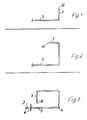
- the method according to the invention is characterized in that the frame leg to be bent for the final closing is filled with desiccant and then from its still open end face emptied or partially emptied up to or beyond the bending area and then bent and connected with its open end face to that of the first frame leg.
- the mechanical outlay becomes particularly inexpensive and low if the curved hollow profile is removed from the filling station after filling the still open frame leg and inserted into a bending station. Although this makes it necessary to handle the workpiece after filling and before bending - as a rule by an operator - this eliminates the need for complex devices that carry out all process steps to be carried out at one and the same place and are therefore coordinated with one another in terms of control technology and space would have to.
- the frame leg to be bent can be partially emptied in the bending station - before the bending process.
- this procedure enables a targeted and precise partial emptying to a desired depth, since the blown-in air can be sucked out again together with desiccant and a suction of more desiccant, for example entrained air is avoided by the perforations provided in such frame legs.
- the compressed air can be supplied in the interior of the hollow profile approximately at the distance from its open end face which is completely or partially freed from desiccant, and suction can also be drawn off on this end face of the hollow profile. What is evacuated by the suction vacuum is thus simultaneously supplied with compressed air at the desired emptying depth, so that the section in between can be emptied with great certainty and accuracy without unwanted areas lying deeper or further away from the open end face of the hollow profile be freed from desiccant. It can even be largely prevented by blowing compressed air in the interior of the hollow profile that too much desiccant can flow into the emptying area.
- An expedient way of closing the frame can consist overall in that the frame leg (s) to be connected to close the frame is partially or completely filled undosed, then in the area of their open end faces up to beyond the plug-in area of a straight connector on the one hand or in or over the bending area of the protruding frame legs are emptied on the other hand and that the frame leg no longer to be bent before closing and in particular before the last bending process on the other frame leg - preferably with a straight protrusion piece partially protruding from it - is closed.
- This closing of the frame leg piece no longer to be bent with the straight connection piece has the advantage that the final closing of the frame can then be accomplished relatively simply by pushing the bent region of the other frame leg with its open end face over this straight connection piece and then in this position can be pressed.
- the above-mentioned device for producing a spacer frame containing a desiccant can be characterized in order to achieve the object in that the filling station and the station for producing the last bend and are arranged to close the frame independently of one another or spatially separated.
- each of these workstations can be configured very simply and inexpensively by machine, while an operator is generally required for the transfer from the filling station to the bending station.
- this is more profitable for smaller quantities than a device which is complex in terms of spatial arrangement and control and in which filling, bending and closing are to take place automatically at one and the same point.
- the bending station is located directly adjacent to the filling station and is preferably arranged on the same machine frame. An operator then only needs to move the filled, partially completed frame around and only have to walk relatively short distances.
- the device can have an emptying device for emptying a partial region of a frame leg from its open end face. So much desiccant can be removed from the filled frame leg that its last bend is not hindered.
- An embodiment of the device of its own worthy of protection may consist in that the emptying device has a suction opening for attachment to the open end face of the frame leg and that in addition to this suction opening connected to a pressure sink, a compressed air supply is provided, the outlet opening of which is spaced apart to the suction mouth of the suction device and which can be inserted into the front opening of the hollow profile.
- the required air or gas content is supplied by the device itself, so that an uncontrolled sucking in of air, for example through the perforations of the frame legs and thereby an extensive emptying of the frame leg is avoided.
- the compressed air supply is designed as a tube, the outer cross section of which is smaller than the inner cross section of the hollow profile.
- this compressed air supply can be inserted into the hollow section to be partially emptied, so that the compressed air then takes place in the corresponding desired depth within the hollow section with the appropriate distance from its open end face, i.e. suction from the open end face leads to the space between to empty the open face and the mouth of the tube in a targeted and controlled manner.
- a particularly expedient and easy-to-use embodiment results if the compressed air tube protrudes from the suction opening of the suction device and the length of its projection over the suction opening is almost equal to the length of the region of the hollow profile to be emptied.
- the emptying device can be fastened in front of the bending station and can be delivered with the suction opening and the compressed air tube in alignment with the hollow profile, i.e. it can be part of the manufacturing device, but in this embodiment the emptying device can also be a hand-held device which can be attached to a hollow profile by an operator.
- the compressed air supply tube can be extended and / or - can be exchanged for at least one tube with a different length. In this way, the length range that is to be emptied as seen from the open end of a hollow profile can be varied.
- the emptying device is a hand-held device, it can be connected on the one hand to a pressure source and on the other hand to a pressure sink via movable lines, in particular hoses or the like, and preferably have a handle for handling.
- the compressed air tube can protrude approximately centrally from the suction opening. Air and desiccant can be sucked off correspondingly uniformly over the larger outer cross section of the hollow profile, the air itself being able to be supplied in a targeted manner centrally inside the hollow profile.
- the procedure for partially emptying a bending area close to an open end face and the device provided for this purpose can also be used if Profiles filled with desiccant from the outset - possibly with thick-walled webs - should be bent and joined in a last step.
- the bending process itself can, however, take place due to the lack of desiccant inside the hollow profile 3 with a narrower radius of curvature and modified bending tools, since the risk of the hollow profile 3 bursting is reduced or eliminated, especially on its web located outside in the bending area.
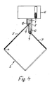
- the frame legs or profile pieces 5 and 7 starting from this open position can now be filled with desiccant 1, as is shown in FIG 4 recognizes.
- the frame 2 is expediently suspended so vertically that one of its diagonals runs vertically and the two profile pieces 5 and 7 to be filled are directed obliquely downward from their open end face.
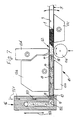
- This partial emptying takes place from the open end face 10 of this frame leg 5, in that air 14 or gas is blown in over a partial cross section of the hollow profile 3 according to FIG. 7 and air 14 and desiccant 1 are sucked out over the adjacent partial cross sections.
- the compressed air 14 is supplied in the interior of the hollow profile 3 approximately at the distance from its open end face 10 which is to be completely or partially freed from desiccant 1.
- the suction is carried out on the end face 10 of this hollow profile 3.
- the frame leg or legs 5 and 7 to be connected to close the frame 2 are undosed - possibly partially or - in the exemplary embodiment completely, which represents the simplest possibility, as shown in FIG. 4, then in the region of their open end faces 10 to over the plug-in area of a straight connector 15 on the one hand and especially emptied into or over the bending area 12 of the protruding frame leg 5, the frame leg 7, which is no longer to be bent, being closed on the other frame leg 5 before the last bending process - preferably with the already mentioned, partially protruding straight connecting piece 15.
- the partial emptying of the frame leg 7, which is no longer to be bent, does not necessarily have to be carried out with compressed air and suction, since only relatively little desiccant has to be removed in the region of the straight connector 15, possibly also the plug-in of the straight connector 15 is achieved by compressing the desiccant filling of this frame leg 7 can be and no bending point must be cleared.
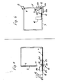
- the device with which the above-described method can essentially be carried out can be seen above all in FIGS. 4 to 6. It has the filling device 8 already mentioned on the one hand and the big device 13 on the other, which also includes the emptying device 16, which is particularly useful 7 - next to the bending device 13 - is clearly shown.
- FIGS. 4 and 5 make it clear that the filling station having the filling device 8 and the station for producing the last bend in the bending region 12 of the hollow profile are arranged with the bending device 13 independently of one another or spatially separated, so that the frame 2 is transferred from the filling device 8 to the bending device 13, a handling process is carried out by an operator or possibly also by an automatic gripping and transport device.
- Mutual control engineering and constructive consideration of the Filling device 8 with its units on the one hand and the bending device 13 with their units, in particular a guide jaw 13a, a clamping jaw 13b, a bending jaw 13c, a counter-holder 13d and a bending roller 13e, is advantageously not required, so that the mechanical outlay is kept correspondingly low can be.
- the bending station can be located directly adjacent to the filling station and possibly arranged on the same machine frame. However, it is also possible for each of these stations, on the one hand the filling device 8 and on the other hand the bending device 13, to have its own holder.
- the overall device also includes the previously mentioned emptying device 16, with which a partial area of the frame leg 5 can be emptied from its open end face 10.
- this emptying device 16 is attached or arranged on the bending station in front of the bending device 13, that is to say in the region of the open end face 10 of the profile piece or frame leg 5 clamped between the guide jaw 13a and the clamping jaw 13b.
- This emptying device 16 has a suction opening 17 for attachment to the open end face 10 of the frame leg 5.
- a compressed air supply is provided, the outlet opening 18 of which is at a distance from the suction opening 17 of the suction device and which can be inserted into the front opening of the hollow profile 3.
- the emptying device 16 can be delivered according to FIGS. 5 to 7 with the suction opening 17 and the compressed air supply and its outlet opening 18 in alignment with the hollow profile 3 or the frame leg 5 in the bending station, but can also be offset laterally during the actual bending process and, according to FIG. 6, are stored on the guide jaw 13a by means of the compressed air supply in a corresponding opening.
- the compressed air supply is designed as a tube 19, the outer cross section of which is smaller than the inner cross section of the hollow profile 3, so that it can be inserted into the hollow profile 3 from the open end face 10 according to FIG. 7.
- the compressed air tube 19 protrudes from the suction opening 17 of the suction device and the length of its protrusion above the suction opening 17 is almost equal to the length of the area of the hollow profile 3 to be emptied.
- Fig. 7 it is indicated that the outflow from the outlet opening 18 Compressed air 14 can detect and blow out a certain surrounding area even in a somewhat greater depth of the hollow profile 3, this blowing-out process being supported by the suction from the end face 10 and being directed into the desired emptying direction.
- the negative pressure is of course greatest in the area of the open end face 10 of the hollow profile 3, that is to say a higher pressure is present in the bending area 12, which can prevent the drying agent which is not to be removed from uncontrolled and unwanted reflow into the area to be emptied.
- the compressed air tube 19 protrudes approximately centrally from the suction opening 17, which results in correspondingly favorable flow conditions.
- the compressed air or suction channels then run parallel to one another in the interior of the emptying device 16. Their cross sections also take into account the different pressure ratios.
- the Flow directions are indicated by the arrows Pf1 - compressed air supply - and PF2 - desiccant suction.
- the compressed air supply tube 19 can be extended or exchanged for a tube 19 of a different length in order to allow adaptation to different dimensions between the bending area 12 and the open end face 10.
- the device can also be constructed or controlled so that this area to be emptied always has the same length regardless of other dimensions of the frame 2, which is also advantageous with regard to the bending device 13 and the arrangement of the counter-holder 13d.
- the emptying device 16 can be connected on the one hand to a pressure source and on the other hand to a pressure sink via movable lines, in particular via hoses or the like, in order to achieve the feed movements according to the double arrow Pf3 and also a movement of its tube 19 in the direction of orientation of the hollow profile 3 to enable. It may also have a handle for handling, i.e. be a more or less mobile device 16 that an operator can set up and use as needed. If the compressed air supply on the one hand and the suction pressure on the other hand can be switched on separately from one another, the emptying device 16 can under certain circumstances also be used as a blowgun if desiccant which is accidentally scattered on the device is to be removed.
- the emptying device 16 is also used in other applications in which a channel or the like leading into the depth is to be emptied can be because, on the one hand, an overpressure can be created inside such a channel, the outflow of which, together with the material to be removed, is supported from the open side by suction through the suction opening 17, so that a very specific combined suction and blowing can take place .
- an initially desiccant-free hollow profile 3 is bent several times to form the frame corners, but is still left open in the area of a last corner. Then one or expediently both frame legs 5 and 7 leading to this open position can be filled with desiccant 1 and the frame 2 can then be finally closed.
- the frame leg 5 to be bent for final closing is first completely filled with desiccant, then emptied from its still open end face 10 to or beyond the bending area 12 and then bent over, with no desiccant now being able to hinder this last bend, and then with its open face 10 connected to the other open frame leg 7.
- the bending processes are carried out by the desiccant. Nevertheless, a very simple device for performing this method is possible because the hollow profile 3 can be removed from the filling device 8 after filling the still open frame legs and inserted into the bending device 13, which can be the same bending device 13 that the made previous bends.
- the emptying down to the last bending area can be carried out in a targeted manner with a combined suction and blowing device and without the risk of removing too much desiccant.
Landscapes
- Engineering & Computer Science (AREA)
- Civil Engineering (AREA)
- Structural Engineering (AREA)
- Securing Of Glass Panes Or The Like (AREA)
- Audible-Bandwidth Dynamoelectric Transducers Other Than Pickups (AREA)
- Automobile Manufacture Line, Endless Track Vehicle, Trailer (AREA)
Priority Applications (1)
| Application Number | Priority Date | Filing Date | Title |
|---|---|---|---|
| AT90123966T ATE88539T1 (de) | 1989-12-23 | 1990-12-12 | Verfahren und vorrichtung zum herstellen eines abstandhalter-rahmens. |
Applications Claiming Priority (2)
| Application Number | Priority Date | Filing Date | Title |
|---|---|---|---|
| DE3942808 | 1989-12-23 | ||
| DE3942808A DE3942808A1 (de) | 1989-12-23 | 1989-12-23 | Verfahren und vorrichtung zum herstellen eines abstandhalter-rahmens |
Publications (2)
| Publication Number | Publication Date |
|---|---|
| EP0435076A1 true EP0435076A1 (fr) | 1991-07-03 |
| EP0435076B1 EP0435076B1 (fr) | 1993-04-21 |
Family
ID=6396334
Family Applications (1)
| Application Number | Title | Priority Date | Filing Date |
|---|---|---|---|
| EP90123966A Expired - Lifetime EP0435076B1 (fr) | 1989-12-23 | 1990-12-12 | Méthode et installation de fabrication d'un dispositif d'écartement |
Country Status (4)
| Country | Link |
|---|---|
| EP (1) | EP0435076B1 (fr) |
| AT (1) | ATE88539T1 (fr) |
| DE (2) | DE3942808A1 (fr) |
| DK (1) | DK0435076T3 (fr) |
Cited By (5)
| Publication number | Priority date | Publication date | Assignee | Title |
|---|---|---|---|---|
| WO1992010635A1 (fr) * | 1990-12-05 | 1992-06-25 | Skovgaard & Co. A/S | Procede et appareil servant a remplir un cadre d'ecartement ferme avec un agent de dessiccation |
| US5390406A (en) * | 1993-03-12 | 1995-02-21 | Lisec; Peter | Process and apparatus for the partial filling of spacer frames with material |
| AT410909B (de) * | 2000-05-09 | 2003-08-25 | Lisec Peter | Verfahren und vorrichtung zum biegen von hohlprofilleisten zu abstandhalterrahmen für isolierglasscheiben |
| US6619098B2 (en) | 2001-08-28 | 2003-09-16 | Peter Lisec | Process and device for bending of hollow profile strips into spacer frames for insulating glass panes |
| WO2020070245A1 (fr) | 2018-10-04 | 2020-04-09 | Lisec Austria Gmbh | Procédé et dispositif de fabrication d'un cadre d'écartement pour verre isolant |
Families Citing this family (2)
| Publication number | Priority date | Publication date | Assignee | Title |
|---|---|---|---|---|
| DE4223730C2 (de) * | 1992-07-18 | 1996-02-29 | Bayer Isolierglasfab Kg | Verfahren und Vorrichtung zum Füllen und Herstellen eines Abstandhalter-Rahmens für Isolierglasscheiben |
| DE4402726A1 (de) * | 1994-01-29 | 1995-08-10 | Bayer Isolierglasfab Kg | Verfahren und Vorrichtung zum Herstellen eines Abstandhalter-Rahmens für Isolierglasscheiben |
Citations (4)
| Publication number | Priority date | Publication date | Assignee | Title |
|---|---|---|---|---|
| FR2405907A1 (fr) * | 1977-10-15 | 1979-05-11 | Erbsloeh Julius & August | Entretoise pour vitrage isolant a vitres multiples, procede et dispositif pour sa fabrication |
| DE3221986A1 (de) * | 1982-06-11 | 1983-12-15 | Fr. Xaver Bayer Isolierglasfabrik Kg, 7807 Elzach | Maschine zum herstellen eines abstandhaltenden innenrahmens fuer eine isolierglasscheibe |
| EP0249946A2 (fr) * | 1986-06-19 | 1987-12-23 | Karl Lenhardt | Procédé et dispositif pour la fabrication d'un cadre d'espacement pour vitres isolantes |
| DE3740922A1 (de) * | 1987-12-03 | 1989-06-22 | Bayer Isolierglasfab Kg | Verfahren und vorrichtung zur herstellung eines abstandhalter-rahmens |
Family Cites Families (2)
| Publication number | Priority date | Publication date | Assignee | Title |
|---|---|---|---|---|
| DE3346671C1 (de) * | 1983-12-23 | 1985-07-04 | Karl 7531 Neuhausen Lenhardt | Verfahren zum Formen der Ecken von Abstandhalterrahmen fuer randverklebte Isolierglasscheiben |
| DE3740921A1 (de) * | 1987-12-03 | 1989-06-15 | Bayer Isolierglasfab Kg | Vorrichtung zur herstellung einer biegung an einem hohlen rechteck-profil |
-
1989
- 1989-12-23 DE DE3942808A patent/DE3942808A1/de active Granted
-
1990
- 1990-12-12 AT AT90123966T patent/ATE88539T1/de not_active IP Right Cessation
- 1990-12-12 DE DE9090123966T patent/DE59001257D1/de not_active Expired - Fee Related
- 1990-12-12 DK DK90123966.5T patent/DK0435076T3/da active
- 1990-12-12 EP EP90123966A patent/EP0435076B1/fr not_active Expired - Lifetime
Patent Citations (4)
| Publication number | Priority date | Publication date | Assignee | Title |
|---|---|---|---|---|
| FR2405907A1 (fr) * | 1977-10-15 | 1979-05-11 | Erbsloeh Julius & August | Entretoise pour vitrage isolant a vitres multiples, procede et dispositif pour sa fabrication |
| DE3221986A1 (de) * | 1982-06-11 | 1983-12-15 | Fr. Xaver Bayer Isolierglasfabrik Kg, 7807 Elzach | Maschine zum herstellen eines abstandhaltenden innenrahmens fuer eine isolierglasscheibe |
| EP0249946A2 (fr) * | 1986-06-19 | 1987-12-23 | Karl Lenhardt | Procédé et dispositif pour la fabrication d'un cadre d'espacement pour vitres isolantes |
| DE3740922A1 (de) * | 1987-12-03 | 1989-06-22 | Bayer Isolierglasfab Kg | Verfahren und vorrichtung zur herstellung eines abstandhalter-rahmens |
Cited By (5)
| Publication number | Priority date | Publication date | Assignee | Title |
|---|---|---|---|---|
| WO1992010635A1 (fr) * | 1990-12-05 | 1992-06-25 | Skovgaard & Co. A/S | Procede et appareil servant a remplir un cadre d'ecartement ferme avec un agent de dessiccation |
| US5390406A (en) * | 1993-03-12 | 1995-02-21 | Lisec; Peter | Process and apparatus for the partial filling of spacer frames with material |
| AT410909B (de) * | 2000-05-09 | 2003-08-25 | Lisec Peter | Verfahren und vorrichtung zum biegen von hohlprofilleisten zu abstandhalterrahmen für isolierglasscheiben |
| US6619098B2 (en) | 2001-08-28 | 2003-09-16 | Peter Lisec | Process and device for bending of hollow profile strips into spacer frames for insulating glass panes |
| WO2020070245A1 (fr) | 2018-10-04 | 2020-04-09 | Lisec Austria Gmbh | Procédé et dispositif de fabrication d'un cadre d'écartement pour verre isolant |
Also Published As
| Publication number | Publication date |
|---|---|
| EP0435076B1 (fr) | 1993-04-21 |
| ATE88539T1 (de) | 1993-05-15 |
| DE3942808C2 (fr) | 1992-09-03 |
| DE59001257D1 (de) | 1993-05-27 |
| DK0435076T3 (da) | 1993-08-23 |
| DE3942808A1 (de) | 1991-06-27 |
Similar Documents
| Publication | Publication Date | Title |
|---|---|---|
| DE69605992T2 (de) | Vorrichtung und Verfahren zum Evakuieren von Beuteln | |
| EP0318749B1 (fr) | Méthode et dispositif pour construire des cadres d'écartement | |
| AT403350B (de) | Biegemaschine zum herstellen eines abstandhaltenden innenrahmens für eine isolierglasscheibe | |
| DE102019206392A1 (de) | Schalenverschließmaschine | |
| EP0435076B1 (fr) | Méthode et installation de fabrication d'un dispositif d'écartement | |
| DE2709088C2 (de) | Vorrichtung und Verfahren zum Verpacken von zusammendrückbaren Materialien | |
| DE202014100309U1 (de) | Fülleinrichtung zum Befüllen von Mauersteinen | |
| DE2522094B2 (de) | Behälter aus Kunststoff und Blasform für seine Herstellung | |
| EP3017933B1 (fr) | Dispositif de soudage par application laser destinee a la fabrication additive d'objets tridimensionnels | |
| DE2911831C2 (de) | Vorrichtung zum Herstellen von Abstandshalterahmen für Isolierglasscheiben | |
| DE2757886A1 (de) | Verfahren und vorrichtung zur herstellung von eckverbindungen von metallrahmen | |
| EP0290747A2 (fr) | Station de remplissage pour une machine de remplissage et de fermeture de cartouches | |
| EP1781430A1 (fr) | Procede et dispositif pour produire un profile creux a soudure longitudinale | |
| DE2710481C3 (de) | Verfahren und Vorrichtung zum Vakuumbzw. Unterdruckformen einer Gießform | |
| DE1632147A1 (de) | Vorrichtung zur Befeuchtung von Tabak mit Dampf | |
| DE2739239C2 (de) | Vorrichtung zum Herstellen eines rohrförmigen Hohlkörpers, insbes. von Verpackungsteilen aus mehrschichtigem Verbundmaterial | |
| DE19956046A1 (de) | Verfahren und Vorrichtung zur Herstellung eines Abstandhalterrahmens für Isolierglasscheiben | |
| DE3445660A1 (de) | Vorrichtung zum einbringen von grifflochstanzungen in taktweise bewegte kunststoffolienbahnen | |
| DE2727297B2 (de) | Verfahren und Einrichtung zum Herstellen von Gießereisandformen | |
| DE4319078C2 (de) | Verfahren und Formherstellungsmaschine zur Herstellung von Gußformen oder Gußformteilen aus Formsand | |
| DE1461849C3 (fr) | ||
| CH662522A5 (de) | Formmaschine zum herstellen von gasgehaerteten sandformen und verfahren zum betrieb dieser formmaschine. | |
| DE1241047B (de) | Verfahren und Maschine zum Herstellen von Giessformen | |
| EP0580040B1 (fr) | Procédé et dispositif pour le remplissage et la fabrication d'un cadre d'espacement pour vitres isolantes | |
| DE671452C (de) | Verfahren und Vorrichtung zum Herstellen geklebter, konischer Faltschachteln, Papierbehaelter u. dgl. |
Legal Events
| Date | Code | Title | Description |
|---|---|---|---|
| PUAI | Public reference made under article 153(3) epc to a published international application that has entered the european phase |
Free format text: ORIGINAL CODE: 0009012 |
|
| AK | Designated contracting states |
Kind code of ref document: A1 Designated state(s): AT BE CH DE DK ES FR GB IT LI NL SE |
|
| 17P | Request for examination filed |
Effective date: 19910709 |
|
| 17Q | First examination report despatched |
Effective date: 19920305 |
|
| GRAA | (expected) grant |
Free format text: ORIGINAL CODE: 0009210 |
|
| AK | Designated contracting states |
Kind code of ref document: B1 Designated state(s): AT BE CH DE DK ES FR GB IT LI NL SE |
|
| PG25 | Lapsed in a contracting state [announced via postgrant information from national office to epo] |
Ref country code: SE Effective date: 19930421 Ref country code: ES Free format text: THE PATENT HAS BEEN ANNULLED BY A DECISION OF A NATIONAL AUTHORITY Effective date: 19930421 |
|
| REF | Corresponds to: |
Ref document number: 88539 Country of ref document: AT Date of ref document: 19930515 Kind code of ref document: T |
|
| REF | Corresponds to: |
Ref document number: 59001257 Country of ref document: DE Date of ref document: 19930527 |
|
| ITF | It: translation for a ep patent filed | ||
| GBT | Gb: translation of ep patent filed (gb section 77(6)(a)/1977) |
Effective date: 19930618 |
|
| ET | Fr: translation filed | ||
| REG | Reference to a national code |
Ref country code: DK Ref legal event code: T3 |
|
| PLBI | Opposition filed |
Free format text: ORIGINAL CODE: 0009260 |
|
| 26 | Opposition filed |
Opponent name: GLASTECHNISCHE INDUSTRIE PETER LISEC GMBH, Effective date: 19931005 |
|
| NLR1 | Nl: opposition has been filed with the epo |
Opponent name: GLASTECHNISCHE INDUSTRIE PETER LISEC GMBH |
|
| PLBL | Opposition procedure terminated |
Free format text: ORIGINAL CODE: EPIDOS OPPC |
|
| PGFP | Annual fee paid to national office [announced via postgrant information from national office to epo] |
Ref country code: CH Payment date: 19990315 Year of fee payment: 9 |
|
| PLBM | Termination of opposition procedure: date of legal effect published |
Free format text: ORIGINAL CODE: 0009276 |
|
| STAA | Information on the status of an ep patent application or granted ep patent |
Free format text: STATUS: OPPOSITION PROCEDURE CLOSED |
|
| 27C | Opposition proceedings terminated |
Effective date: 19981218 |
|
| PGFP | Annual fee paid to national office [announced via postgrant information from national office to epo] |
Ref country code: BE Payment date: 19990517 Year of fee payment: 9 |
|
| PGFP | Annual fee paid to national office [announced via postgrant information from national office to epo] |
Ref country code: NL Payment date: 19990531 Year of fee payment: 9 |
|
| NLR2 | Nl: decision of opposition | ||
| PGFP | Annual fee paid to national office [announced via postgrant information from national office to epo] |
Ref country code: DK Payment date: 19991220 Year of fee payment: 10 |
|
| PG25 | Lapsed in a contracting state [announced via postgrant information from national office to epo] |
Ref country code: LI Free format text: LAPSE BECAUSE OF NON-PAYMENT OF DUE FEES Effective date: 19991231 Ref country code: CH Free format text: LAPSE BECAUSE OF NON-PAYMENT OF DUE FEES Effective date: 19991231 Ref country code: BE Free format text: LAPSE BECAUSE OF NON-PAYMENT OF DUE FEES Effective date: 19991231 |
|
| BERE | Be: lapsed |
Owner name: FRANZ XAVER BAYER ISOLIERGLASFABRIK K.G. Effective date: 19991231 |
|
| PG25 | Lapsed in a contracting state [announced via postgrant information from national office to epo] |
Ref country code: NL Free format text: LAPSE BECAUSE OF NON-PAYMENT OF DUE FEES Effective date: 20000701 |
|
| NLV4 | Nl: lapsed or anulled due to non-payment of the annual fee |
Effective date: 20000701 |
|
| PGFP | Annual fee paid to national office [announced via postgrant information from national office to epo] |
Ref country code: GB Payment date: 20001205 Year of fee payment: 11 |
|
| PG25 | Lapsed in a contracting state [announced via postgrant information from national office to epo] |
Ref country code: DK Free format text: LAPSE BECAUSE OF NON-PAYMENT OF DUE FEES Effective date: 20001212 |
|
| PGFP | Annual fee paid to national office [announced via postgrant information from national office to epo] |
Ref country code: FR Payment date: 20001215 Year of fee payment: 11 |
|
| PGFP | Annual fee paid to national office [announced via postgrant information from national office to epo] |
Ref country code: DE Payment date: 20001229 Year of fee payment: 11 Ref country code: AT Payment date: 20001229 Year of fee payment: 11 |
|
| REG | Reference to a national code |
Ref country code: DK Ref legal event code: EBP |
|
| PG25 | Lapsed in a contracting state [announced via postgrant information from national office to epo] |
Ref country code: GB Free format text: LAPSE BECAUSE OF NON-PAYMENT OF DUE FEES Effective date: 20011212 Ref country code: AT Free format text: LAPSE BECAUSE OF NON-PAYMENT OF DUE FEES Effective date: 20011212 |
|
| REG | Reference to a national code |
Ref country code: GB Ref legal event code: IF02 |
|
| PG25 | Lapsed in a contracting state [announced via postgrant information from national office to epo] |
Ref country code: DE Free format text: LAPSE BECAUSE OF NON-PAYMENT OF DUE FEES Effective date: 20020702 |
|
| GBPC | Gb: european patent ceased through non-payment of renewal fee |
Effective date: 20011212 |
|
| PG25 | Lapsed in a contracting state [announced via postgrant information from national office to epo] |
Ref country code: FR Free format text: LAPSE BECAUSE OF NON-PAYMENT OF DUE FEES Effective date: 20020830 |
|
| REG | Reference to a national code |
Ref country code: FR Ref legal event code: ST |
|
| PG25 | Lapsed in a contracting state [announced via postgrant information from national office to epo] |
Ref country code: IT Free format text: LAPSE BECAUSE OF NON-PAYMENT OF DUE FEES Effective date: 20051212 |