EP0435131B1 - Tastatur mit festgehaltenen Tasten - Google Patents
Tastatur mit festgehaltenen Tasten Download PDFInfo
- Publication number
- EP0435131B1 EP0435131B1 EP90124541A EP90124541A EP0435131B1 EP 0435131 B1 EP0435131 B1 EP 0435131B1 EP 90124541 A EP90124541 A EP 90124541A EP 90124541 A EP90124541 A EP 90124541A EP 0435131 B1 EP0435131 B1 EP 0435131B1
- Authority
- EP
- European Patent Office
- Prior art keywords
- keys
- support
- framework
- plane
- captive
- Prior art date
- Legal status (The legal status is an assumption and is not a legal conclusion. Google has not performed a legal analysis and makes no representation as to the accuracy of the status listed.)
- Expired - Lifetime
Links
- 230000037431 insertion Effects 0.000 claims abstract 2
- 238000003780 insertion Methods 0.000 claims abstract 2
- 210000004027 cell Anatomy 0.000 description 19
- 238000000926 separation method Methods 0.000 description 4
- 238000004519 manufacturing process Methods 0.000 description 3
- 238000000465 moulding Methods 0.000 description 3
- 239000000463 material Substances 0.000 description 2
- 238000000034 method Methods 0.000 description 2
- 210000002445 nipple Anatomy 0.000 description 2
- 230000006978 adaptation Effects 0.000 description 1
- 238000004026 adhesive bonding Methods 0.000 description 1
- 238000010276 construction Methods 0.000 description 1
- 230000003247 decreasing effect Effects 0.000 description 1
- 238000010586 diagram Methods 0.000 description 1
- 238000005304 joining Methods 0.000 description 1
- 238000007493 shaping process Methods 0.000 description 1
Images


Classifications
-
- H—ELECTRICITY
- H01—ELECTRIC ELEMENTS
- H01H—ELECTRIC SWITCHES; RELAYS; SELECTORS; EMERGENCY PROTECTIVE DEVICES
- H01H13/00—Switches having rectilinearly-movable operating part or parts adapted for pushing or pulling in one direction only, e.g. push-button switch
- H01H13/70—Switches having rectilinearly-movable operating part or parts adapted for pushing or pulling in one direction only, e.g. push-button switch having a plurality of operating members associated with different sets of contacts, e.g. keyboard
-
- H—ELECTRICITY
- H01—ELECTRIC ELEMENTS
- H01H—ELECTRIC SWITCHES; RELAYS; SELECTORS; EMERGENCY PROTECTIVE DEVICES
- H01H2233/00—Key modules
- H01H2233/002—Key modules joined to form button rows
- H01H2233/004—One molded part
- H01H2233/006—Separating individual keys after mounting
Definitions
- the present invention relates to a keyboard with captive keys, having the characteristics of the preamble of claim 1. Such a keyboard maintains the keys as soon as they are in place, regardless of its orientation.
- keyboards essentially comprise a support provided with cells and keys which are introduced into these cells.
- the support is a simple plate pierced with a hole for each key; the keys each have a body whose section is slightly less than that of the hole, this body ending at one of its ends by a shoulder whose section is greater than that of the hole.
- the keys are inserted, shoulder up, in the substantially horizontal plate. This provision prohibits turning the plate during assembly or disassembly of the device, without having removed the keys before.
- a first solution consists in fixing a mask on the face of the support by which the keys have been introduced. This mask has openings whose geometry coincides with that of the cells of the support, these openings having a reduced dimension compared to the shoulder of the keys.
- the term "shoulder" should be understood, in general, like any mechanical stop device.
- This solution adds two stages in the manufacture of the keyboard, the realization of the mask and its fixing, which generates a complication of the process and an additional cost.
- a second solution is to use a click system.
- an element In such a system or two elements must snap, an element carries at least one elastic blade provided with a hook, this hook coming to be embedded in a cavity of the other element.
- the assembly of the two elements requires, first, that the blade deviates from its rest position. This travel must therefore be taken into account, which increases the size of the device.
- the hooks have a minimum dimension which is a function of manufacturing constraints. This minimum dimension does not allow make certain types of keyboard which have small dimensions and / or whose keys are very close to each other.
- the elements (the support and the key) of the keyboard are made by molding, the shaping of the hook leads to making an undercut mold. This complicates the development of the mold, if however the small dimensions of the element considered do not prohibit making such a mold for technological reasons.
- the present invention thus relates to a keyboard with captive keys, the implementation of which is not affected by the limitations set out above.
- the fixing means comprise rivets integral with the support which cooperate with eyelets secured to the frame, the heads of the rivets being crushed after the juxtaposition of the frame and the support.
- the breaking surfaces are substantially parallel to the bases of the keys with which they are associated.
- the captive key keyboard embodying the invention comprises a support and a cluster of keys.
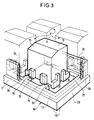
- the intermediate plane defines the thickness of the support 1 relative to the outside plane outside the zone where the cells 2 appear, while the support plane corresponds to a reinforced thickness of this support in the vicinity of the cells.
- These cells which extend from the external plane 3 to the support plane 5 are delimited by walls 6 perpendicular to these planes.
- Rivets 7 the function of which will be explained later, are projecting from the support surface 5.
- the frame of the cluster has its base on the lower plane while the keys extend from the rupture plane to the upper plane with the exception of certain projections.
- a key 11 comprises a body 15 which has the shape of a beveled rectangular parallelepiped on its upper face and whose base inscribed in the rupture plane 14, has dimensions slightly smaller than those of a cell 2.
- Two stops 17, 18 form protrusions on each short side of the body 15 perpendicular to its base. They extend from a level between the lower plane 12 and the rupture plane to a stop level between the rupture plane and the upper plane. In addition, the length of the base of the body 15 increased by twice the thickness of these stops is greater than the length of a cell 2.
- Two protrusions 19 form protrusions on each long side of the body 15 perpendicular to its base. They extend from the rupture plane to the abutment level defined above, which defines their thicknesses. In addition, the width of the base of the body 15 increased by twice the thickness of these protuberances is greater than the width of a cell 2.
- a key 11 is connected to the framework 10 only by a part of each protuberance 19 in the rupture plane.
- the intersection of the projections of the protuberance and the framework 10 in this plane defines a rupture surface 20 whose dimensions are small with respect to those of the protuberance, in particular its thickness.
- This breaking surface corresponds to the smallest section achievable on the assembly consisting of a key 11 and the framework 10. It is oriented, in this case, parallel to the breaking plane, which represents a particular case embodying the invention .
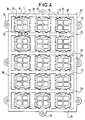
- the cluster of keys appears in its entirety in FIG. 4 where it is represented seen from below, that is to say on the lower plane side 12.
- the keys 11 are arranged in five rows of three units, like the cells 2, of way to coincide with these.
- the framework 10 of the cluster comprises six cross members 21, 22, 23, 24, 25, 26 delimiting these rows and two parallel beams 28, 29 joining these cross members outside the keys 11.
- the crosspieces and the beams are delimited by the lower plane 12 and the rupture plane 13.
- Each cross member comprises, facing the protrusions 19 of the keys 11, studs 30 projecting and overlapping these protrusions on the rupture surfaces 20 previously defined.
- These nipples are delimited by the lower plane and the rupture plane, which defines their thicknesses.
- a rupture surface has dimensions which are small compared to those of a nipple, in particular its thickness.
- eyelets 33 On the periphery of the framework 10, that is to say on the end crosspieces 21, 26 and on the beams 28, 29, are arranged eyelets 33 whose axis is perpendicular to the plane of the keyboard, these eyelets being projecting outward from the cluster.
- FIGS. 5 and 6 represent the central button 11 of the first row of the cluster with the portions of the cross members 21, 22 which face it, respectively seen from below and views in section.
- a rib 35 which has not been drawn in FIG. 4, extends all along the crosspieces and beams along the medians of these. It is perpendicular to the rupture plane 13 and, having a uniform thickness, develops from this plane to a contact plane 36.
- This contact plane 36 is located between the level of the stop, the stops 17, 18 and the protrusions 19, and the upper plane 14.
- An eyelet 33 also extends from the rupture plane 13 to the contact plane 36. It comprises a cavity 39 which opens onto the rupture plane and which is extended by a bore 40 of a reduced diameter compared to the size of the cavity. This bore opens onto the contact plane 36 while flaring. Its diameter is slightly greater than that of the rivets 7 which appear on the support 1.
- the eyelets 33 in an amount equal to the rivets 7, are arranged on the cluster so as to coincide with these when the keys 11 coincide with the cells 2.
- the set of eyelet-rivet pairs constitutes an example of fastening means for the framework 10 to the support 1.
- These fixing means can use any other known assembly technique such as gluing, hot deformation, etc.
- the final realization of the keyboard requires two operations, the fixing of the framework 10 to the support 1 and the separation of the keys 11 from the framework.
- the fixing of the frame to the support is carried out in a simple manner by crushing the heads of the rivets 7, which can be carried out with a single tool.
- rupture surfaces 20 which in the example presented are parallel to the rupture plane can take a different inclination if they are sufficiently distant from a plane perpendicular to this rupture plane, a condition necessary for the keys to remain captive of the frame support.
Landscapes
- Input From Keyboards Or The Like (AREA)
- Mobile Radio Communication Systems (AREA)
- Circuits Of Receivers In General (AREA)
- Telephone Function (AREA)
- Plural Heterocyclic Compounds (AREA)
- Telephone Set Structure (AREA)
Claims (3)
- Tastatur mit unverlierbaren Tasten, die einen mehrere Zellen (2) aufweisenden Träger (1) enthält, mehrere Tasten (11), die in je eine Zelle eingeführt sind, wobei diese Tasten von einem Vielfach kommen, das weiter ein Gerippe (10) enthält, wobei jede dieser Tasten mit diesem Gerippe ursprünglich verbunden ist und mindestens in einem abschließenden Herstellungsschritt von dieser entlang einer Reißfläche (20) getrennt wird, wobei die Tasten (11) außerdem in dem Vielfach gemäß einer Verteilung angeordnet sind, die mit der der Löcher zusammenfällt, dadurch gekennzeichnet, daß- jede der Reißflächen (20) einer Taste in Bezug auf die Einführungsrichtung dieser Taste geneigt ist, damit die Tasten in der Einheit aus Träger und Gerippe gefangen bleiben,- das Gerippe (10) fluchtend auf dem Träger (1) durch Befestigungsmittel befestigt ist.
- Tastatur mit unverlierbaren Tasten nach dem vorhergehenden Anspruch, dadurch gekennzeichnet, daß die Befestigungsmittel fest mit dem Träger (1) verbundene Nieten (7) aufweisen, die mit Ösen (33) im Gerippe (10) zusammenwirken, wobei die Köpfe der Nieten nach dem Zusammenfügen des Gerippes (10) und des Trägers (1) gestaucht werden.
- Tastatur mit unverlierbaren Tasten nach Anspruch 1 oder 2, dadurch gekennzeichnet, daß die Reißflächen (20) im wesentlichen parallel zu den Basen der Tasten (11) sind, denen sie zugeordnet sind.
Applications Claiming Priority (2)
| Application Number | Priority Date | Filing Date | Title |
|---|---|---|---|
| FR8917344A FR2656735B1 (fr) | 1989-12-28 | 1989-12-28 | Clavier a touches captives. |
| FR8917344 | 1989-12-28 |
Publications (2)
| Publication Number | Publication Date |
|---|---|
| EP0435131A1 EP0435131A1 (de) | 1991-07-03 |
| EP0435131B1 true EP0435131B1 (de) | 1995-06-21 |
Family
ID=9389083
Family Applications (1)
| Application Number | Title | Priority Date | Filing Date |
|---|---|---|---|
| EP90124541A Expired - Lifetime EP0435131B1 (de) | 1989-12-28 | 1990-12-18 | Tastatur mit festgehaltenen Tasten |
Country Status (6)
| Country | Link |
|---|---|
| EP (1) | EP0435131B1 (de) |
| AT (1) | ATE124166T1 (de) |
| DE (1) | DE69020322T2 (de) |
| DK (1) | DK0435131T3 (de) |
| ES (1) | ES2073500T3 (de) |
| FR (1) | FR2656735B1 (de) |
Families Citing this family (3)
| Publication number | Priority date | Publication date | Assignee | Title |
|---|---|---|---|---|
| IT1277814B1 (it) * | 1995-02-02 | 1997-11-12 | Peisa Srl | Interruttore elettrico e metodo per la sua fabbricazione |
| ES2304891B1 (es) | 2007-04-04 | 2009-06-04 | Bsh Electrodomesticos España, S.A. | Teclado para un aparato electrodomestico y metodo para instalarlo. |
| DE102008010217B3 (de) * | 2008-02-20 | 2009-09-10 | Preh Gmbh | Schalttafelanordnung mit Bedien- und Abdeckteil aus einem gemeinsamen Grundteil sowie ein Kraftfahrzeug und ein Haushaltsgerät damit |
Family Cites Families (5)
| Publication number | Priority date | Publication date | Assignee | Title |
|---|---|---|---|---|
| US3860771A (en) * | 1973-10-29 | 1975-01-14 | Chomerics Inc | Keyboard switch assembly with dome shaped actuator having associated underlying contactor means |
| SE433675B (sv) * | 1981-04-09 | 1984-06-04 | Ericsson Telefon Ab L M | Forfarande for tillverkning av en tryckknappsats |
| IT1155482B (it) * | 1982-04-02 | 1987-01-28 | Olivetti & Co Spa | Tastiera a contatti e metodo per la fabbricazione della stessa |
| US4638151A (en) * | 1984-05-25 | 1987-01-20 | Canon Kabushiki Kaisha | Keyboard of an electronic apparatus |
| US4609791A (en) * | 1984-12-20 | 1986-09-02 | Itt Corporation | Flexible diaphragm keypad and method of manufacture |
-
1989
- 1989-12-28 FR FR8917344A patent/FR2656735B1/fr not_active Expired - Fee Related
-
1990
- 1990-12-18 EP EP90124541A patent/EP0435131B1/de not_active Expired - Lifetime
- 1990-12-18 ES ES90124541T patent/ES2073500T3/es not_active Expired - Lifetime
- 1990-12-18 DE DE69020322T patent/DE69020322T2/de not_active Expired - Fee Related
- 1990-12-18 DK DK90124541.5T patent/DK0435131T3/da active
- 1990-12-18 AT AT90124541T patent/ATE124166T1/de not_active IP Right Cessation
Also Published As
| Publication number | Publication date |
|---|---|
| FR2656735A1 (fr) | 1991-07-05 |
| FR2656735B1 (fr) | 1996-04-26 |
| ATE124166T1 (de) | 1995-07-15 |
| DE69020322T2 (de) | 1995-11-02 |
| ES2073500T3 (es) | 1995-08-16 |
| EP0435131A1 (de) | 1991-07-03 |
| DE69020322D1 (de) | 1995-07-27 |
| DK0435131T3 (da) | 1995-10-30 |
Similar Documents
| Publication | Publication Date | Title |
|---|---|---|
| FR2521181A1 (fr) | Cadre a broder specialement adapte a une mise en place precise et rapide d'un article sur le plateau d'une machine a broder | |
| EP0027415A1 (de) | Brillengestell | |
| EP0435131B1 (de) | Tastatur mit festgehaltenen Tasten | |
| EP0847848A1 (de) | Gegenstand bestehend aus einem Formteil und einem eingelegten dekorativen Element und Verfahren zu seiner Herstellung | |
| EP0549979A1 (de) | Gliederarmband, insbesondere für Uhren | |
| FR2783080A1 (fr) | Plateau et boitier de reception d'au moins un disque circulaire de stockage d'informations | |
| FR2798766A1 (fr) | Boite a disque cd | |
| EP1789288B1 (de) | Kunststoffkarosserieteil mit einem mit dem teil einstückiggeformten grill | |
| FR2528244A1 (fr) | Outil d'insertion de contact | |
| BE1006304A4 (fr) | Matelas et son procede de realisation. | |
| WO2002061712A1 (fr) | Dispositif de presentation d"echantillons notamment pour produits cosmetiques | |
| EP1479324A1 (de) | Auflageteller eines Multielemet-Lattenrostes für ein Bett | |
| CH683582B5 (fr) | Pièce d'horlogerie comportant un élément fixé rigidement sur une pièce de base en matière plastique. | |
| CA2048084A1 (fr) | Procede de fabrication d'une carte a microcircuit et carte obtenue par ce procede | |
| EP1089144B1 (de) | Kontaktbügel für multifunktionellen Druckknopf | |
| EP0978300A1 (de) | Verfahren zur Herstellung einer Figur für ein Tischfussballspiel, danach hergestellte Figur und mit solch einer Figur ausgerüstetes Tischfussballspiel | |
| FR2619170A1 (fr) | Dispositif permettant d'assembler deux corps l'un avec l'autre et procede de realisation de ce produit | |
| EP1009000B1 (de) | Dreidimensionales Zentrierung- und Positionierungssystem für Taster | |
| FR2762134A1 (fr) | Sous-ensemble et procede de fabrication de dispositifs tels que des claviers | |
| EP0911276A1 (de) | Schachtel aus geschaümtem Material, Herstellungsverfahren und Form dafür | |
| FR2771304A1 (fr) | Procede de fabrication d'une figurine pour jeu de table, figurine ainsi obtenue et jeu de table pourvu d'une telle figurine | |
| CH683987A5 (fr) | Emballage composite pour oeufs, fruits ou objets fragiles. | |
| EP4711864A1 (de) | Dynamische anzeigevorrichtung zur integration in eine uhr | |
| FR2463007A1 (fr) | Clavier avec une coiffe recouvrant au moins une touche, en particulier pour des machines de mise en forme de texte et/ou de composition photographique | |
| FR2599342A1 (fr) | Dispositif et procede pour le conditionnement d'une serie d'objets a fixer sur une plaque |
Legal Events
| Date | Code | Title | Description |
|---|---|---|---|
| PUAI | Public reference made under article 153(3) epc to a published international application that has entered the european phase |
Free format text: ORIGINAL CODE: 0009012 |
|
| AK | Designated contracting states |
Kind code of ref document: A1 Designated state(s): AT BE CH DE DK ES FR GB IT LI NL SE |
|
| 17P | Request for examination filed |
Effective date: 19911230 |
|
| 17Q | First examination report despatched |
Effective date: 19940912 |
|
| GRAA | (expected) grant |
Free format text: ORIGINAL CODE: 0009210 |
|
| AK | Designated contracting states |
Kind code of ref document: B1 Designated state(s): AT BE CH DE DK ES FR GB IT LI NL SE |
|
| REF | Corresponds to: |
Ref document number: 124166 Country of ref document: AT Date of ref document: 19950715 Kind code of ref document: T |
|
| REF | Corresponds to: |
Ref document number: 69020322 Country of ref document: DE Date of ref document: 19950727 |
|
| ITF | It: translation for a ep patent filed | ||
| REG | Reference to a national code |
Ref country code: ES Ref legal event code: FG2A Ref document number: 2073500 Country of ref document: ES Kind code of ref document: T3 |
|
| GBT | Gb: translation of ep patent filed (gb section 77(6)(a)/1977) |
Effective date: 19950829 |
|
| REG | Reference to a national code |
Ref country code: DK Ref legal event code: T3 |
|
| PLBE | No opposition filed within time limit |
Free format text: ORIGINAL CODE: 0009261 |
|
| STAA | Information on the status of an ep patent application or granted ep patent |
Free format text: STATUS: NO OPPOSITION FILED WITHIN TIME LIMIT |
|
| 26N | No opposition filed | ||
| PGFP | Annual fee paid to national office [announced via postgrant information from national office to epo] |
Ref country code: GB Payment date: 19971113 Year of fee payment: 8 Ref country code: FR Payment date: 19971113 Year of fee payment: 8 |
|
| PGFP | Annual fee paid to national office [announced via postgrant information from national office to epo] |
Ref country code: DK Payment date: 19971117 Year of fee payment: 8 |
|
| PGFP | Annual fee paid to national office [announced via postgrant information from national office to epo] |
Ref country code: SE Payment date: 19971124 Year of fee payment: 8 Ref country code: CH Payment date: 19971124 Year of fee payment: 8 |
|
| PGFP | Annual fee paid to national office [announced via postgrant information from national office to epo] |
Ref country code: AT Payment date: 19971126 Year of fee payment: 8 |
|
| PGFP | Annual fee paid to national office [announced via postgrant information from national office to epo] |
Ref country code: DE Payment date: 19971128 Year of fee payment: 8 |
|
| PGFP | Annual fee paid to national office [announced via postgrant information from national office to epo] |
Ref country code: NL Payment date: 19971130 Year of fee payment: 8 |
|
| PGFP | Annual fee paid to national office [announced via postgrant information from national office to epo] |
Ref country code: BE Payment date: 19971208 Year of fee payment: 8 |
|
| PGFP | Annual fee paid to national office [announced via postgrant information from national office to epo] |
Ref country code: ES Payment date: 19971216 Year of fee payment: 8 |
|
| PG25 | Lapsed in a contracting state [announced via postgrant information from national office to epo] |
Ref country code: GB Free format text: LAPSE BECAUSE OF NON-PAYMENT OF DUE FEES Effective date: 19981218 Ref country code: DK Free format text: LAPSE BECAUSE OF NON-PAYMENT OF DUE FEES Effective date: 19981218 Ref country code: AT Free format text: LAPSE BECAUSE OF NON-PAYMENT OF DUE FEES Effective date: 19981218 |
|
| PG25 | Lapsed in a contracting state [announced via postgrant information from national office to epo] |
Ref country code: SE Free format text: LAPSE BECAUSE OF NON-PAYMENT OF DUE FEES Effective date: 19981219 Ref country code: ES Free format text: LAPSE BECAUSE OF THE APPLICANT RENOUNCES Effective date: 19981219 |
|
| PG25 | Lapsed in a contracting state [announced via postgrant information from national office to epo] |
Ref country code: LI Free format text: LAPSE BECAUSE OF NON-PAYMENT OF DUE FEES Effective date: 19981231 Ref country code: CH Free format text: LAPSE BECAUSE OF NON-PAYMENT OF DUE FEES Effective date: 19981231 Ref country code: BE Free format text: LAPSE BECAUSE OF NON-PAYMENT OF DUE FEES Effective date: 19981231 |
|
| BERE | Be: lapsed |
Owner name: ALCATEL BUSINESS SYSTEMS Effective date: 19981231 |
|
| PG25 | Lapsed in a contracting state [announced via postgrant information from national office to epo] |
Ref country code: NL Free format text: LAPSE BECAUSE OF NON-PAYMENT OF DUE FEES Effective date: 19990701 |
|
| GBPC | Gb: european patent ceased through non-payment of renewal fee |
Effective date: 19981218 |
|
| REG | Reference to a national code |
Ref country code: CH Ref legal event code: PL |
|
| PG25 | Lapsed in a contracting state [announced via postgrant information from national office to epo] |
Ref country code: FR Free format text: LAPSE BECAUSE OF NON-PAYMENT OF DUE FEES Effective date: 19990831 |
|
| NLV4 | Nl: lapsed or anulled due to non-payment of the annual fee |
Effective date: 19990701 |
|
| REG | Reference to a national code |
Ref country code: FR Ref legal event code: ST |
|
| PG25 | Lapsed in a contracting state [announced via postgrant information from national office to epo] |
Ref country code: DE Free format text: LAPSE BECAUSE OF NON-PAYMENT OF DUE FEES Effective date: 19991001 |
|
| REG | Reference to a national code |
Ref country code: DK Ref legal event code: EBP |
|
| REG | Reference to a national code |
Ref country code: ES Ref legal event code: FD2A Effective date: 20010402 |
|
| PG25 | Lapsed in a contracting state [announced via postgrant information from national office to epo] |
Ref country code: IT Free format text: LAPSE BECAUSE OF NON-PAYMENT OF DUE FEES;WARNING: LAPSES OF ITALIAN PATENTS WITH EFFECTIVE DATE BEFORE 2007 MAY HAVE OCCURRED AT ANY TIME BEFORE 2007. THE CORRECT EFFECTIVE DATE MAY BE DIFFERENT FROM THE ONE RECORDED. Effective date: 20051218 |