EP0435182B1 - Regulierungsvorrichtung für einen wirksamen Betrieb von hydroelektrischen Kraftwerken - Google Patents
Regulierungsvorrichtung für einen wirksamen Betrieb von hydroelektrischen Kraftwerken Download PDFInfo
- Publication number
- EP0435182B1 EP0435182B1 EP90125062A EP90125062A EP0435182B1 EP 0435182 B1 EP0435182 B1 EP 0435182B1 EP 90125062 A EP90125062 A EP 90125062A EP 90125062 A EP90125062 A EP 90125062A EP 0435182 B1 EP0435182 B1 EP 0435182B1
- Authority
- EP
- European Patent Office
- Prior art keywords
- generating unit
- signals
- water
- output
- water level
- Prior art date
- Legal status (The legal status is an assumption and is not a legal conclusion. Google has not performed a legal analysis and makes no representation as to the accuracy of the status listed.)
- Expired - Lifetime
Links
- XLYOFNOQVPJJNP-UHFFFAOYSA-N water Substances O XLYOFNOQVPJJNP-UHFFFAOYSA-N 0.000 claims description 116
- 238000001514 detection method Methods 0.000 claims description 30
- 238000012545 processing Methods 0.000 claims description 23
- 238000012937 correction Methods 0.000 claims description 10
- 230000010354 integration Effects 0.000 claims description 9
- 238000011144 upstream manufacturing Methods 0.000 claims description 6
- 230000005856 abnormality Effects 0.000 claims description 2
- 238000010248 power generation Methods 0.000 claims description 2
- 238000003745 diagnosis Methods 0.000 claims 1
- 238000010586 diagram Methods 0.000 description 4
- 101000911772 Homo sapiens Hsc70-interacting protein Proteins 0.000 description 2
- 241000220317 Rosa Species 0.000 description 1
- 230000002159 abnormal effect Effects 0.000 description 1
- 230000003466 anti-cipated effect Effects 0.000 description 1
- 230000006866 deterioration Effects 0.000 description 1
- 230000002349 favourable effect Effects 0.000 description 1
- 230000007774 longterm Effects 0.000 description 1
- 238000012423 maintenance Methods 0.000 description 1
- 238000005259 measurement Methods 0.000 description 1
- 238000000034 method Methods 0.000 description 1
- 238000011017 operating method Methods 0.000 description 1
- 230000010355 oscillation Effects 0.000 description 1
- 230000001105 regulatory effect Effects 0.000 description 1
- 238000010977 unit operation Methods 0.000 description 1
Images




Classifications
-
- F—MECHANICAL ENGINEERING; LIGHTING; HEATING; WEAPONS; BLASTING
- F03—MACHINES OR ENGINES FOR LIQUIDS; WIND, SPRING, OR WEIGHT MOTORS; PRODUCING MECHANICAL POWER OR A REACTIVE PROPULSIVE THRUST, NOT OTHERWISE PROVIDED FOR
- F03B—MACHINES OR ENGINES FOR LIQUIDS
- F03B15/00—Controlling
- F03B15/02—Controlling by varying liquid flow
- F03B15/04—Controlling by varying liquid flow of turbines
- F03B15/06—Regulating, i.e. acting automatically
-
- Y—GENERAL TAGGING OF NEW TECHNOLOGICAL DEVELOPMENTS; GENERAL TAGGING OF CROSS-SECTIONAL TECHNOLOGIES SPANNING OVER SEVERAL SECTIONS OF THE IPC; TECHNICAL SUBJECTS COVERED BY FORMER USPC CROSS-REFERENCE ART COLLECTIONS [XRACs] AND DIGESTS
- Y02—TECHNOLOGIES OR APPLICATIONS FOR MITIGATION OR ADAPTATION AGAINST CLIMATE CHANGE
- Y02E—REDUCTION OF GREENHOUSE GAS [GHG] EMISSIONS, RELATED TO ENERGY GENERATION, TRANSMISSION OR DISTRIBUTION
- Y02E10/00—Energy generation through renewable energy sources
- Y02E10/20—Hydro energy
Definitions
- the present invention relates to control systems for high-efficiency operation of a plural number of generating units according to the first part of claim 1 (US-A-4 467 216).
- the invention is especially directed to control systems for hydroelectric power stations that can efficiently operate generating units using the correlation between the amount and capacity of a storage reservoir and the control elements.
- the inflow water an occasion for being used as waterworks water and agricultural water taken downstream from the generating units, and a single generating unit of small capacity for utilization water when it is necessary to maintain discharge to ensure a constant amount of water for generating units.
- a plural number of normal capacity generating units are provided .
- the normal capacity generating units are used to generate power when there is normal operation for a relatively large amount of water, and the small capacity generating units are used in winter and periods of abnormal drought when it is difficult to ensure the discharge of a constant amount of water.
- FIG. 2 shows one example of a water system of such a hydroelectric power station.
- the water from the water intake 1 has its intake flow adjusted by a gate 2 and is taken in, to flow into a head tank or serge tank 4 via a water channel 3.
- the water that is stored in the head tank 4 is discharged to the discharge outlet 8 after it has passed through the turbines of the first through third generating units 5, 6 and 7 and been used to generate power, and is then guided to downstream hydroelectric power stations and for direct usage.
- the first and second generating units 5 and 6 are of regular capacity and the third generating unit 7 is of small capacity.
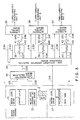
- FIG. 1 shows a conventional control system for this purpose. This system is basically configured from a calculation unit 9 and control units 21, 25 and 26.
- the gate degree of opening gauge 10 is for the detection of the degree of opening of a gate 2 provided at the water intake 1, and is provided with a contact 11 that turns on when the gate 2 is in the fully closed status, a contact 12 that turns on when the degree of opening of the gate 2 is more than a rated value A1 corresponding to the maximum flow amount of the generating unit 7, and a contact 13 that turns on when the degree of opening of the gate 2 is a rated value A2 corresponding to the maximum flow amount of one of the generating unit 5 and the generating unit 6.
- the rated value A2 is greater than the rated value A1.
- the signal S1 from the contact 11 is inverted and applied to one of the input terminals of the AND circuit 14, the signal S2 from the contact 12 is inverted and applied to the other of the input terminals of the AND circuit 14 and is also applied to one of the input terminals of the AND gate 15.
- the signal S3 from the contact 13 is inverted and applied to the other of the input terminals of the AND circuit 15 and in the status where it is not inverted, is also applied to a trigger input terminal of the timer 16.
- the output signal S4 from the AND circuit 14 is applied to the trigger input terminal of a timer 17 and the output signal S5 from the AND circuit 15 is applied to the trigger input terminal of a timer 18.
- the timer 16 When the signal S3 is applied to the trigger input terminal, the timer 16 outputs the signal S6 after a certain amount of time has elapsed from when the degree of opening of the gate 2 changes until the time that the flow amount to the head tank 4 changes. This output signal S6 is applied to the input terminals of the OR circuits 19 and 20.
- the timer 17 When the signal S4 is applied to the trigger input terminal, the timer 17 outputs the signal S7 after a certain amount of time corresponding to the sum of water arrival/reduction time and the time required to change the degree of opening of the gate 2 from the fully closed position to the rated value A1, and this output signal S7 is applied to the start/stop processing means of the control unit 21 so as to control the generating unit 7.
- the timer 18 When the signal S5 is applied to the trigger input terminal, the timer 18 outputs a signal S8 after the lapse of a certain time corresponding to the sum of water arrival/reduction time and the time required to change the degree of opening of the gate 2 from the rated value A1 to the rated value A2, and this output signal S8 is applied to one of the input terminals of the AND circuit 22 and the AND circuit 23.
- the contact 24 is turned on to generate a signal S9 and operate generating unit 5 when this generating unit 5 is to be given priority of operation over generating unit 6, and this signal S9 is inverted and applied to the other of the input terminals of the AND circuit 22.
- the output signal S10 of the AND circuit 22 is applied to the other of the input terminals of the OR circuit 20, and the output signal S11 of the AND circuit 23 is applied to the other input terminal of the OR circuit 19.
- the output signal S12 of the OR circuit 19 is applied to the start/stop control means 25a of the control apparatus 25 in order to control the generating unit 5, and the output signal S13 of the OR circuit 20 is applied to the start/stop control means 26a in order to control the generating unit 6.
- the water level gauge 27 is to detect the water level of the head tank 4, and its detection signal S14 is respectively applied to the water level adjustment control means 21b, 25b, 26b of the control units 21, 25 and 26.
- the contact 28 is to turn on when the selection signal S14 is smaller than a rated value, and its signal S15 is respectively applied to the start/stop control means 21a, 25a, 26a of the control units 21, 25 and 26.
- the head tank water level detection portion 29 is connected to water level gauge 27 by a contact 28.
- the water level adjustment control means 21b, 25b and 26b judge the head tank water level on the basis of the detection signals S13, and controls the output of the generating units 7, 5 and 6, and those control signals S16, S17 and S18 control the load limit values of the governors 21c, 25c and 26c of the generating units 7, 5 and 6.
- the contact 11 turns ON, and the contacts 12 and 13 turn OFF for the status where the gate 2 is fully closed, and all of the contacts 11, 12 and 13 are OFF when the gate starts to open, contact 12 turns ON when the degree of opening of the gate 2 is a rated value A1 or more, and the contact 11 turns ON and contacts 12 and 13 turn ON when the degree of opening is the rated value A2 or more.
- the signal S1 provides ON output and the signals S2 and S3 provide OFF output and so the signals S4 and S5 output from the AND circuits 14 and 15 are OFF.
- the signals S6, S7 and S8 are not output from the timers 16, 17 and 18 and so the control apparatus 21, 25 and 26 do not start.
- the signals S1, S2 and S3 are all OFF until the time when the degree of opening becomes the rated value A1, and this causes the signal S4 to be ON and so this signal is applied to the control apparatus 21 at the point when a time set for the timer 17 has elapsed from the timing of when the signal S4 rose to ON output.
- the generating unit 7 is started in phase with the timing at which the gate 2 starts to open, and the water that flows in from the water intake 1 reaches the head tank 4.
- the signal S1 is OFF output and the signals S2 and S3 are ON output so that the signal S5 is made ON output, and the signal S8 becomes ON output at the time when a set time of the timer 18 has elapsed from the timing at which the signal S5 became ON output and rose.
- the AND circuit 23 is in a status where it can be operated and so the signal S11 is ON output. Accordingly, in this case, the signal S12 is ON output and is applied to the control unit 25.
- the first generating unit 5 is started by this.
- the signal S1 is OFF output and the signals S2 and S3 are ON output so that the signal S6 turns ON after the elapse of a time set for the timer 16, from the timing of the rise of the signal S3 to ON output.
- the signals S12 and S13 are ON output and so the second generating unit 6 is started after starting the first generating unit 5.
- the generating units 5, 6 and 7 are suitably controlled in accordance with the degree of opening of the gate 2.
- the water level adjustment control means 21b, 25b and 26b performs respective load control of the governors 21c, 25c and 26c of the generating units 7, 5 and 6.
- the start/stop control means 21a, 25a and 26a of the control units 21, 25 and 26 stops the generating units 7, 5 and 6.
- the flow amount from the gate 2 is regulated by the degree of opening when there is a constant water level and so when the water level at the water intake 1 changes, the actual flow amount and the flow amount anticipated by the degree of opening of the gate are not in agreement, and as a result there occurs overflows and unnecessary change in the water level of the head tank, and there is the unwanted consequence of the trip of the generating unit due to the drop in the water level.
- the flow amount from the water intake 1 is made Qi
- the maximum flow of the small capacity third generating unit is made Q3m
- the two generating units 5 and 6 are respectively operating at their flow (Qi/2) and so the generating efficiency of the entire power station deteriorates.
- US-4 476 716 discloses a control system for a hydroelectric power station comprising several generating units supplied with water from a flow hydropower source, which comprises means for detecting the individual flow to each generating unit, flow control means for interrupting flow to individual generating units, means for detecting the efficiency of the generating units and control logic means for interrupting flow to generating units operating below the rated efficiency.
- the present invention has as object the provision of a control apparatus for a hydroelectric power station which can improve the efficiency of the entire power station, average the operating ratio of each of the generating units, lengthen the life of the equipment, improve the economy and realize stable operation of the water level in a head tank.
- a control system according to claim 1.
- the present invention is provided with an intake flow calculation means to calculate the flow amount to the water storage reservoir, and a flow distribution means to use the calculation results of the intake flow calculation means to calculate the flow that is to be distributed to each of the generating units so that the total output is maximized.
- each of the items of equipment is suitable combined and so the efficiency of the power station becomes more favorable and the life of the generating units and other equipment is lengthened.
- FIG. 3 shows a control apparatus for a hydroelectric power station, and according to a first embodiment of the present invention. Moreover, this control apparatus is applied to the hydroelectric power station having the water system shown in FIG. 2 and portions that are the same or equivalent to similar portions in FIG. 1 and FIG. 2 are indicated with the same numerals.
- the control system of the first embodiment is provided with a water level gauge 31 provided to the water intake 1, a gate degree of opening gauge 33, a flow characteristic calculation means 32 that supplies the measurement values of these instruments 31 and 33, and a water level gauge 27 provided to the head tank 4 in the same manner as the conventional embodiment.
- the control system is configured from a high-efficiency operation selection processing means 34 that controls the operation of the generating units 5, 6 and 7 on the basis of the signals S14 and S33 output from the water level gauge 27 and the calculation means 32 so that the operation of the generating units 5, 6 and 7 is the most efficient, the automatic control means 35, 36 and 37 that control the generating units 5, 6 and 7, and the objective value calculation means 38, 39 and 40 provided between the automatic control means 35, 36 and 37 and said processing means 34 so as to calculate the power objective values of the generating units 5, 6 and 7.
- deviation calculators 41, 42 and 43 are provided between the automatic control means 35, 36 and 37 and the processing means 34.
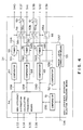
- the selection processing means is configured from comparators 51, 52, 63, 64 and 65, a water level correction means 53, a high-efficiency distribution calculation processing means 54, timers 55, 56 and 57, switches 58, 60 and 66, and adders 59 and 61, all connected as shown in the figure.
- the water level gauge 31 is for the detection of the water level at the water intake 1, and the detection signal S31 is supplied to the flow characteristic calculation means 32.
- the gate degree of opening gauge 33 is to detect a degree of opening of the gate 2, and the detection signals S32 (analog signals) are supplied to the flow characteristic calculation means 32.
- the flow characteristic calculation means 32 calculates the water quantity Qa that flows through the gate 2 on the basis of equation (1) and the detection signal S31 and detection signal S32, and the results of calculation are supplied to the high-efficiency operation selection means 34 as flow intake amount signals S33.
- Qa f (Ha, Ga) (1)
- Ha expresses the water level of the water intake 1
- Ga expresses the degree of opening of the gate 2.
- the water quantity Qa is expressed as a function of the water level of the water intake and the degree of opening of the gate.
- the high-efficiency operation selection means 34 calculates the flow to be distributed to the generating units 5, 6 and 7 and these calculation results are respectively output as flow amount objective value signals S37, S38 and S39 to the calculation means 38, 39 and 40.
- the high-efficiency operation selection means 34 forms start command signals S40, S41 and S42 for the generating units 5, 6 and 7, and respectively outputs them to the automatic control means 35, 36 and 37.
- the calculation means 38, 39 and 40 calculates the power objective value of the generating units 5, 6 and 7 and those calculation results are applied to the deviation calculators 41, 42 and 43 as power objective value signals S43, S44 and S45.
- the actual output signals S46, S47 and S48 of the generating units 5, 6 and 7 and output from the automatic control means 35, 36 and 37 are applied to the deviation calculators 41, 42 and 43 which calculate the respective deviations between the actual output signals S46, S47 and S48, and the power objective value signals S43, S44 and S45, and these calculation results are output as output deviation signals S49, S50 and S51 to the automatic control means 35, 36 and 37.
- the operation of the generating units 5, 6 and 7 starts and the load of the generating units 5, 6 and 7 is controlled so that the output deviation signals S49, S50 and S51 tend towards zero.
- the signals S49, S50 and S51 are obtained by outputting actual output signals S46, S47 and S48 corresponding to the actual output of the generating units 5, 6 and 7 to the deviation calculation means 41, 42 and 43.
- the failure signals S34, S35 and S36 are output to the high efficiency operation selection means 34.
- FIG. 4 shows an example of a high-efficiency operation selection means 34.
- the detection signals S14 of the water level gauge 27 are applied to the comparators 51 and 52 and to the water level correction means 53.
- the comparator 51 detects that the detection signal S14 is lower than the lower limit reference value corresponding to the lower limit value for the water level of the head tank 4, and those detection signals are applied to the high-efficiency distribution calculation means 54 as start lock signals S55.
- the comparator 52 detects that the detection signals S14 are greater than the upper limit reference value corresponding to the upper limit of the water level of the head tank 4, and those detection signals S56 are applied to the timers 55, 56 and 57.
- the water level correction means 53 corrects for changes in the correlation between the intake amount and the head tank water level that occur over the years, and those correction signals S57 are applied to one of the input terminals of the adder 59 via the contact 58a of the switch 58, and are also applied to one of the input terminals of the adder 61 via the contact 60a of the switch 60.
- the high-efficiency distribution calculation means 54 calculates the flow amounts Q1, Q2 and Q3 to be given to the respective generating units so that the total sum P of the output of the generating units 5, 6 and 7 is maximized, and the calculation results are output as the distribution flow amount signals S58, S59 and S60.
- the distribution flow amount signals S58 are applied to the comparator 63 and to the other input terminal of the adder 59 via the contact 58b of the switch 58.
- the distribution flow amount signals S59 are applied to the comparator 64 and to the other input terminal of the adder 61 via the contact 60b of the switch 60.
- the distribution flow amount signals S60 are applied to the comparator 65 and are also output as flow amount objective value signals S39 via the contact 66a of the switch 66.
- P1, P2 and P3 are the respective outputs of the generating units 5, 6 and 7 and these are expressed in the following manner by equations (4) through (6).
- P1 K1 (Q1) (4)
- P2 K2 (Q2) (5)
- P3 K3 (Q3) (6)
- Kn (Qn) expresses the flow-output characteristic of the respective generating units.
- the high-efficiency distribution calculation means 54 sets the value for the distribution flow amount signals S58, S59 and S60 at zero.
- the calculation processing described above is executed when the failure signals S34, S35 and S36 are input, and the corresponding flow amounts Q1, Q2 and Q3 are in the status where they have been set to zero beforehand.
- the comparators 63, 64 and 65 are for detecting that the respective flow distribution signals S58, S59 and S60 are above the non-load flow amount for the generating units 5, 6 and 7, and those detection signals S61, S62 and S63 are applied to the trigger input terminal of the timers 55, 56 and 57.
- the timers 55, 56 and 57 are so that there is no unnecessary start/stop during gate operation and so that the influence of water arrival/reduction is removed, and respectively output the signals S64, S65 and S66 when respective set times have elapsed from when the detection signals S61, S62 and S63 have been applied to the trigger input terminal. Furthermore, when signals S56 from the comparator 52 are applied, the respective set times are switched to the set time that shortens the water arrival time. Also, these detection signals S64, S65 and S66 are respectively output as the start command signals S40, S41 and S42 and the switches 58, 60 and 66 are turned on.
- the adder 59 is to add the distribution flow amount signal S58 and the correction signal S57 and the results of addition are output as the flow amount objective value signals S37.
- the adder 61 is for adding the distribution flow amount signals S59 and the correction signals S57 and the results of addition are output as the flow amount objective value signals S38, while the output signals of the switch 66 are output as flow amount objective value signals S39.
- flow amount signals S33 corresponding to the flow quantity Qa from the flow characteristic calculation means 32 are applied to the high-efficiency operation selection means 34 and as has been described above, the high-efficiency distribution calculation means 54 calculates the intake flow amounts Q1, Q2 and Q3 that are to be distributed to the generating units 5, 6 and 7, and outputs corresponding distribution flow amount signals S58, S59 and S60.
- the signals S64, S65 and S66 are output from the timers 55, 56 and 57 upon the elapse of respective times set for the timers 55, 56 and 57 after the signals S61, S62 and S63 have been output, and this starts the start processing for the automatic control means 35, 36 and 37 to start the generating units 5, 6 and 7.
- the switches 58, 60 and 66 are turned on, so that the signal S58 and the signal S57 is input to the adder 59, and the addition results are output to the calculation means 38 as the flow amount objective value signals S37, the signal S59 and the signal S57 are input to the adder 61 and the addition result is output to the calculation means 39 as the flow amount objective value signal S38, and the signal S60 is output to the calculation means 40 as the flow amount objective value signal S39.
- the power objective value signals S43, S44 and S45 corresponding to the flow amount objective values at that time are output from the calculation means 38, 39 and 40, and output deviation signals S49, S50 and S51 corresponding to the deviation between those power objective values and the actual output, are output from the deviation calculators 41, 42 and 43 to the automatic control means 35, 36 and 37.
- the generating units 5, 6 and 7 are controlled so that their output becomes the objective value and as a result, the total sum of the output of the hydroelectric power station is controlled so as to be maximum.
- FIG. 5 is a flow chart indicating an outline of the operation described above.
- the water level of the water intake 1 and the degree of opening of the gate 2 are used as the basis for the flow characteristic calculation means 32 to calculate the intake flow amount to the head tank 4 (step ST1).
- the signals S14 from the water level gauge 27 that detects the water level of the head tank 4 are output to the flow characteristic calculation means 32 along with the signals S33 (step ST2).
- step ST3 When it has been judged in step ST3 that the water amount Qa does not exceed the total sum "Q1 + Q2 + Q3" , then the processing skips to step ST5, and a judgment is made for whether the water amount Qa exceeds the sum "Q1 + Q2" of the water amount Q1 and Q2 necessary for efficient operation of the 1st and 2nd generating units that have a large generation capacity.
- step ST5 if it is judged that the water amount Qa is less than the total sum "Q1 + Q2 + Q3" and greater than the sum "Q1 + Q2" of the water amount Q1 and Q2 necessary for efficient operation of the large-capacity 1st and 2nd generating units, that is, when "Q1 + Q2" ⁇ Qa ⁇ Q1 + Q2 + Q3 , then the processing skips to step ST6 and a decision is made to stop the generating unit 7 and perform efficient simultaneous operation for the generating units 5 and 6 only.
- step ST5 if it is judged that "Qa ⁇ Q1 + Q2" then, the processing skips to the judgment block of step ST7, and a judgment is made for whether simultaneous efficient operation is possible for the one of the large-capacity generating units 5 and 6, and the small-capacity generating unit 7, that is if "Q1 (or Q2) + Q3 ⁇ Qa” . If "Q1 (or Q2) + Q3 ⁇ Qa” in step ST7, then a decision is made (in step ST8) for the simultaneous efficient operation of one of the large-capacity generating units 5 and 6, and the small-capacity generating unit 7.
- step ST7 if it is judged in step ST7 that "Qa ⁇ Q1 (Q2) + Q3" then the processing skips to step ST9 and a judgment is made for whether “Q1 (Q2) ⁇ Qa ⁇ Q1 (Q2) + Q3" . If it is judged that "Q1 (Q2) ⁇ Qa” in ST9, then in step 10, a command is output to the automatic control means 35 or 36 so that there is efficient operation of one of the generating units 5 or 6. As in the previously described step ST8, the determination of the control command in this step ST10 is to operate either of the plural number of generating units with priority and so the operation continues until steps ST8 and ST10, and a decision is made as to which is to be given priority operation in step ST11. The detailed configuration for performing this priority control is described below for the second embodiment, with reference to FIG. 6.
- step ST9 when it is judged that "Qa ⁇ Q1 (or Q2)", the control process proceeds to step 12 where a judgment is made for whether or not "Q3 ⁇ Qa". If it is judged in step ST12 that "Q3 ⁇ Qa” then, the operation of one of the large-capacity generating units 5 and 6 is stopped and efficient operation is preformed using only the small-capacity generating unit 7.
- step ST14 a command is given to each of the automatic control means 35, 36 and 37 so that the three generating units 5, 6 and 7 are all operated so that the total efficiency is greatest for the selected mode whether that be the case for step 4, or the case for steps ST6, ST11 and ST13.
- step ST12 when it is judged that "Qa ⁇ Q3", the operation proceeds to step ST15 and the operation of all generating units 5, 6 and 7 is stopped. In this case, maintenance discharge is performed so as to ensure the necessary water amount in the ancillary facilities downstream.
- the water level of the water intake 1 and the degree of opening of the gate 2 are used as the basis for suitably calculating the flow amount from the gate 2 and this calculated flow amount is distributed between the generating units 5 and 6 including the small-capacity generating unit 7 so that the total output Pa of the power station is maximized, thereby increasing the power generation efficiency.
- Each generating unit is also operated uniformly so that the operating ratio of each of the generating units is averaged and it is therefore possible to improve the equipment investment.
- FIG. 5 shows a flowchart for describing the operation
- the priority control of the large-capacity generating units 5 and 6 was described as being performed in step ST11.
- the following will be a description of a specific configuration of a second embodiment that performs priority control, with reference to FIG. 6.
- FIG. 6 elements of the configuration that are the same as or equivalent to elements of the configuration of FIG. 4 are represented by the same numerals, and the corresponding descriptions of them are omitted.
- the high-efficiency operation selection means 34 in FIG. 6 is exactly the same as that of the first embodiment.
- the high-efficiency distribution calculation means 54 is also configured so that the priority operation signal S75 for the first large-capacity generating unit 5 and the priority operation signal S76 for the second large-capacity generating unit 6 are supplied from the priority operation control means 70.
- the priority operation control means 70 is configured from AND circuits 71 and 72, integration means 73 and 74, a timer 75 that supplies time signals S69 and S70 which are inverted at a constant cycle, to the integration means 73 and 74.
- the time signal S70 output from the timer 75 switches at a long cycle of from half a year to one year and so when there is priority operation for either of the generating units, then for example, either the signal S69 or the signal S70 is made "high” and the other signal S70 or S69 made "low” so that the first generating unit 5 is operated from January through June, and the second generating unit 6 is operated from July through December.
- the AND circuit 71 of the control means 70 inputs an inverted signals for the parallel operation signal S71 of the first generating unit 5 and parallel operation signal S72 for the second generating unit 6, and outputs the first generating unit priority signal S73, and the AND circuit 72 inputs an inverted signal. for the signal S71, and the signal S72 and outputs the signal S74.
- the integration means 73 inputs the signal S73 and the time signal S69 and outputs a priority operation signal S75 to the processing means 54 when the 1st generating unit priority signal S73 is a significant "1" and when the time signal S69 is also a significant "1".
- the signal S74 output from the AND circuit 72 is supplied to the integration means 74 along with the signal S70 output from the timer 75, and when the signal S74 is a significant "1" and the time signal S70 is also a significant "1", the priority usage time for the second generating unit 6 is integrated with the 2nd generating unit 6 being for priority usage.
- the integration means 73 and 74 alternately output signals S75 and S76, and signals S77 and S78 that are at the same level, to the other integration means 74 and 73, and these signals S77 and S78 clear both priority usage rights when either of the generating units 5 or 6 is used with priority for the set time portions prior to the time set by the timer 75.
- a priority operation control means having the configuration and function as described above, a high-efficiency operation control system for a generating unit and according to a second embodiment enables prevents exceedingly long-term use of either of the generating units when there is provided a plural number of generating units which are used for solitary operation and with priority use, and thus enables uniform use over an averaged time, and thus enables the life of the equipment to be extended.
- first and second embodiments have a gate provided at an upstream water intake but the present invention is also applicable when there is a power station upstream.
- the above described first and second embodiments there are provided three generating units but it is also possible to apply the present invention in the same manner when the hydroelectric power station has more than this number of generating units.
- the start command and the stop command can be separately detected and output to an automatic control means.
Landscapes
- Engineering & Computer Science (AREA)
- Chemical & Material Sciences (AREA)
- Combustion & Propulsion (AREA)
- Mechanical Engineering (AREA)
- General Engineering & Computer Science (AREA)
- Flow Control (AREA)
- Control Of Eletrric Generators (AREA)
- Control Of Water Turbines (AREA)
Claims (11)
- Steuersystem zum Betreiben einer Mehrzahl von Stromerzeugungseinheiten (5, 6, 7) in einem Wasserkraftwerk mit hohem Wirkungsgrad, wobei das Wasserkraftwerk weiterhin einen Kopftank zum Speichern von Einlaufwasser umfaßt, das von der stromaufwärtigen Seite über ein Tor (2) bei einer Wassereinlauföffnung zugeführt wird, gekennzeichnet durch:
eine Tankniveau-Detektionseinrichtung (27) zum Detektieren des Wasserstands des Kopftanks, eine Einlaufniveau-Detektionseinrichtung (31) zum Detektieren des Wasserstands bei der Wassereinlauföffnung und eine Öffnungsgrad-Detektionseinrichtung (33) zum Detektieren des Grades der Öffnung des Tors (2),
eine Flußmengen-Berechnungseinrichtung (32) zum Berechnen der in den Kopftank (4) fließenden Wassermenge auf der Grundlage des detektierten Einlauf-Wasserstands und des detektierten Grads der Öffnung des Tors, welche die Ausgangssignale der Einlaufniveau-Detektionseinrichtung (31) und der Öffnungsgrad-Detektionseinrichtung (33) empfängt und welche ein Ausgangssignal abgibt, das das Ergebnis der Berechnung angibt,
eine Verarbeitungseinrichtung (34), welche den Ausgang der Flußberechnungseinrichtung (32) und der Tankniveau-Detektionseinrichtung (27) empfängt und Flußmengen-Sollwertsignale abgibt, zum Bestimmen von Flußmengen-Sollwerten für jede Stromerzeugungseinheit auf der Grundlage des berechneten Wasserflusses in den Kopftank und des detektierten Wasserstands in dem Kopftank, wobei die Flußmengen-Sollwerte eine derartige Verteilung des Wasserflusses auf die einzelnen Stromerzeugungseinheiten darstellen, daß jede Stromerzeugungseinheit am effizientesten Leistung erzeugen kann und die gesamte Leistungserzeugungs-Abgabe maximiert wird,
mehrere Leistungssollwert-Berechnungseinrichtungen (38, 39, 40), welche die Flußmengen-Sollwertsignale empfangen, wobei jede Leistungssollwert-Berechnungseinrichtung (38, 39, 40) einer entsprechenden Stromerzeugungseinheit (5, 6, 7) zugeordnet ist, für das Berechnen der Leistung konzipiert ist, die am effizientesten von der entsprechenden Stromerzeugungseinheit (5, 6, 7) auf der Grundlage der Flußmengen-Sollwerte erzeugt wird, die durch die Betriebssteuereinrichtung (34) berechnet wurden, und als Ausgang ein Leistungssollwert-Signal liefert, mehrere Abweichungs-Berechnungseinrichtungen (41, 42, 43) zum Berechnen der Abweichung des Leistungssollwerts von den tatsächlichen Abgabewert, welche jeweils einer entsprechenden Stromerzeugungseinheit (5, 6, 7) zugeordnet sind und als einen Eingang das Leistungssollwert-Signal der entsprechenden Leistungs-Berechnungseinrichtung (38, 39, 40) und als zweiten Eingang ein Ist-Abgabesignal von der entsprechenden Stromerzeugungseinheit (5, 6, 7) haben und Signale (S49, S50, S51), welche die Leistungsabweichung angeben, als Steuersignale für die entsprechende Stromerzeugungseinheit abgeben. - Steuersystem nach Anspruch 1, gekennzeichnet durch eine Mehrzahl von automatischen Steuereinrichtungen (35, 36, 37), welche für jede Stromerzeugungseinheit aus der Mehrzahl von Stromerzeugungseinheiten (5, 6, 7) jeweils vorgesehen sind, um den Betrieb der entsprechenden Stromerzeugungseinheit (5, 6, 7) auf der Grundlage von Start-Befehlssignalen (S40, S41, S42) einzuleiten, die von der Verarbeitungseinrichtung (34) abgegeben werden, und um den Betrieb der entsprechenden Stromerzeugungseinheit (5, 6, 7) auf der Grundlage der Leistungsabweichungssignale (S49, S50, S51) zu beenden, die aus der Berechnung der Abweichungs-Berechnungseinrichtung (41, 42, 43) resultieren.
- Steuersystem nach Anspruch 2, dadurch gekennzeichnet, daß die Mehrzahl von automatischen Steuereinrichtungen (35, 36, 37) jeweils Fehlersignale (S34, S35, S36) an die Verarbeitungseinrichtung (34) abgeben und zurückkoppeln, wenn ein anomaler Zustand in einer der Stromerzeugungseinheiten (5, 6, 7) aufgetreten ist.
- Steuersystem nach Anspruch 1, bei dem mindestens eine aus der Mehrzahl von Stromerzeugungseinheiten, die in dem Wasserkraftwerk vorgesehen sind, eine Stromerzeugungseinheit (7) mit geringer Leistungsfähigkeit ist, welche eine geringe Menge an Leistung erzeugt, die einer Wassermenge entspricht, welche das Abgeben einer konstanten Wassermenge gewährleistet, die einer Wassermenge für einen Bedarf eines stromabwärts gelegenen Kraftwerks zugeführt wird, und die restlichen Stromerzeugungseinheiten (5, 6) mit großer Leistungsfähigkeit eine große Menge an Leistung erzeugen, wenn die Menge des zugeführten Wassers ausreichend ist.
- Steuersystem nach Anspruch 4, bei dem die Mehrzahl von Stromerzeugungseinheiten (5, 6) mit großer Leistungsfähigkeit eine erste Stromerzeugungseinheit (5) und eine zweite Stromerzeugungseinheit (6) umfaßt.
- Steuersystem nach Anspruch 4, bei dem die Auswahl-Verarbeitungseinrichtung (34) umfaßt:
eine erste Vergleichseinrichtung (51), welche Detektionssignale (S₁₄) eines Wasserstandsdetektors (27), der den Wasserstand des Kopftanks (4) detektiert, als Grundlage für das Vergleichen eines Referenzwertes für eine untere Schwelle, die eine untere Grenze des Wasserstands des Kopftanks (4) angibt, mit den Detektionssignalen (S₁₄) verwendet,
einen zweiten Vergleicher (52), der einen Referenzwert für eine obere Schwelle, die einen oberen Wasserstand des Kopftanks (4) angibt, mit den Detektionssignalen (S₁₄) vergleicht, eine Wasserstands-Korrektureinrichtung (53), welche die Detektionssignale (S₁₄) korrigiert, indem das Ausmaß der Änderung addiert wird, wenn der Wasserstand des Kopftanks (4), der durch die Detektionssignale (S₁₄) angezeigt wird, sich über die Jahre zu einem Wasserstand verändert hat, der verschieden von dem ursprünglichen ist,
eine Verarbeitungseinrichtung zum Berechnen einer Wassermengenverteilung mit hohem Wirkungsgrad (54), in welche die Flußmengen-Signale, die von der Flußcharakteristik-Berechnungseinrichtung (34) geliefert werden und welche die Flußmenge von dem Wassereinlauf anzeigen, eine Mehrzahl von Fehlerdiagnosesignalen, die von der automatischen Steuereinrichtung geliefert werden, und Vergleichsergebnis-Signale des ersten Vergleichers (51) eingegeben werden und welche Flußverteilungssignale für jede Stromerzeugungseinheit abgibt,
einen dritten, vierten und fünften Vergleicher (63, 64, 65), welche vergleichen, ob die Wassermengenverteilungs-Signale für die Stromerzeugungseinheiten größer als die Flußmengen für die Stromerzeugungseinheiten ohne Last sind oder nicht,
einen ersten, zweiten und dritten Zeitgeber (55, 56, 57), in welche die Detektionssignale, welche als Folge des Vergleichs durch den zweiten Vergleicher (52) anzeigen, daß der Wasserstand des Kopftanks einen oberen Schwellenwert übersteigt, und Wassermengenverteilungs-Signale für jede Stromerzeugungseinheit eingegeben werden, welche von dem dritten, vierten und fünften Vergleicher (63, 64, 65) abgegeben werden, und welche Startbefehls-Signale an jede automatische Steuereinrichtung (35, 36, 37) jeder Stromerzeugungseinheit nach dem Verstreichen einer eingestellten Zeit abgeben,
einen ersten, zweiten und dritten Schalter (58, 60, 66), welche sich einschalten, wenn es eine Korrektur des Wasserstands auf der Grundlage der Wasserstandskorrektur-Signale von der Wasserstands-Korrektureinrichtung und der Flußmengenverteilungs-Signale für jede Stromerzeugungseinheit gibt, und einen ersten und einen zweiten Addierer (59, 61), welche die Flußmengen-Sollwertsignale an jede automatische Steuereinrichtung (35, 36) der ersten und zweiten Stromerzeugungseinheit (5, 6) abgeben, wenn die Schalter eingeschaltet sind. - Steuersystem nach Anspruch 1, welches weiterhin eine Vorrangsbetrieb-Steuereinrichtung (70) umfaßt, welche aufeinanderfolgend eine Stromerzeugungseinheit (5 oder 6), welche im Einzelbetrieb arbeitet, umschaltet, wenn eine bestimmte Zeit erreicht ist, so daß es keinen übermäßigen Betrieb einer bestimmten Stromerzeugungseinheit (5 oder 6) gibt, wenn ein Einzelbetrieb einer Stromerzeugungseinheit (5 oder 6) aus der Mehrzahl von Stromerzeugungseinheiten (5 oder 6) vorliegt.
- Steuersystem nach Anspruch 7, bei dem die Vorrangsbetrieb-Steuereinrichtung (70) innerhalb eines Steuersystems für einen hocheffizienten Betrieb für ein Wasserkraftwerk vorgesehen ist, das zumindest mit einer Stromerzeugungseinheit (7) mit geringer Leistungsfähigkeit, welche eine kleine Menge an Leistung erzeugt, die einer Wassermenge entspricht, welche die Abgabe einer konstanten Wassermenge gewährleistet, und einer Mehrzahl von Stromerzeugungseinheiten (5, 6) mit großer Leistungsfähigkeit versehen ist.
- Steuersystem nach Anspruch 8, bei dem die Mehrzahl von Stromerzeugungseinheiten (5, 6) mit großer Leistungsfähigkeit eine erste Stromerzeugungseinheit (5) und eine zweite Stromerzeugungseinheit (6) umfaßt.
- Steuersystem nach Anspruch 9, bei dem die Vorrangsbetrieb-Steuereinrichtung (70) umfaßt:
eine erste UND-Schaltung (71), in welche Parallelsignale einer ersten Stromerzeugungseinheit (5), welche anzeigen, daß es einen Parallelbetrieb einer ersten Stromerzeugungseinheit (5) gibt, invertierte Signale von Parallelsignalen einer zweiten Stromerzeugungseinheit (6), welche anzeigen, daß es einen Parallelbetrieb einer zweiten Stromerzeugungseinheit (6) gibt, eingegeben werden, und zu der Einzelbetriebs-Signale einer ersten Stromerzeugungseinheit (5) ausgegeben werden, wenn nur eine erste Stromerzeugungseinheit (5) arbeitet,
eine zweite UND-Schaltung (72), in welche Parallelsignale einer zweiten Stromerzeugungseinheit (6), welche anzeigen, daß es einen Parallelbetrieb einer zweiten Stromerzeugungseinheit (6) gibt, invertierte Signale von Parallelsignalen einer ersten Stromerzeugungseinheit (5) eingegeben werden, welche anzeigen, daß es einen Parallelbetrieb einer ersten Stromerzeugungseinheit (5) gibt, und zu der Einzelbetriebs-Signale einer zweiten Stromerzeugungseinheit (6) abgegeben werden, wenn nur eine zweite Stromerzeugungseinheit (6) arbeitet, einen Zeitgeber (75), welcher die Zeit bis zur Abgabe eines Umschaltsignals bei einem konstanten Zyklus von mindestens einem halben Jahr zählt,
eine erste Integrationseinrichtung (73), welche auf der Grundlage der Umschaltsignale von dem Zeitgeber (75) und der Einzelbetriebs-Signale der ersten Stromerzeugungseinheit (5) die Zeit integriert, während der die erste Stromerzeugungseinheit (5) sich im Einzelbetrieb befunden hat, und
eine zweite Integrationseinrichtung (74), welche auf der Grundlage der Umschaltsignale von dem Zeitgeber (75) und der Einzelbetriebs-Signale der zweiten Stromerzeugungseinheit die Zeit integriert, während der sich die zweite Stromerzeugungseinheit im Einzelbetrieb befunden hat. - Steuersystem nach Anspruch 10, bei dem die erste und zweite Integrationseinrichtung (73, 74) solchermaßen funktionieren, daß selbst dann, wenn die Zeit (75) des konstanten Zyklus, die durch den Zeitgeber gesetzt wird, noch nicht gezählt worden ist, die Eingabe von Löschsignalen, welche anzeigen, daß die Einzelbetriebszeit dieser Stromerzeugungseinheit die für das Umschalten erforderliche Zeit überschritten hat, eine Stromerzeugungseinheit auf die andere Seite schaltet und diese einen Einzelbetrieb haben soll.
Applications Claiming Priority (2)
| Application Number | Priority Date | Filing Date | Title |
|---|---|---|---|
| JP329503/89 | 1989-12-21 | ||
| JP1329503A JP2758237B2 (ja) | 1989-12-21 | 1989-12-21 | 水力発電所の発電装置 |
Publications (3)
| Publication Number | Publication Date |
|---|---|
| EP0435182A2 EP0435182A2 (de) | 1991-07-03 |
| EP0435182A3 EP0435182A3 (en) | 1991-08-28 |
| EP0435182B1 true EP0435182B1 (de) | 1994-07-13 |
Family
ID=18222102
Family Applications (1)
| Application Number | Title | Priority Date | Filing Date |
|---|---|---|---|
| EP90125062A Expired - Lifetime EP0435182B1 (de) | 1989-12-21 | 1990-12-21 | Regulierungsvorrichtung für einen wirksamen Betrieb von hydroelektrischen Kraftwerken |
Country Status (3)
| Country | Link |
|---|---|
| EP (1) | EP0435182B1 (de) |
| JP (1) | JP2758237B2 (de) |
| DE (1) | DE69010648T2 (de) |
Cited By (1)
| Publication number | Priority date | Publication date | Assignee | Title |
|---|---|---|---|---|
| AT411485B (de) * | 2001-12-20 | 2004-01-26 | Va Tech Hydro Gmbh & Co | Verfahren und anlage zum regeln des pegelstandes einer stauanlage |
Families Citing this family (11)
| Publication number | Priority date | Publication date | Assignee | Title |
|---|---|---|---|---|
| EP0822332B1 (de) * | 1996-08-02 | 2001-10-17 | VA TECH HYDRO GmbH & Co. | Wasserkraftanlage |
| FR2756647B1 (fr) * | 1996-12-03 | 1999-01-22 | Soc D Services Interbancaires | Procede de transfert entre plusieurs systemes de quantites exprimees dans des unites de mesure differentes |
| DE19717871C2 (de) * | 1997-04-28 | 2000-04-13 | Mitterfelner Anna | Verfahren zur Steuerung von Turbinensystemen in Wasserkraftwerken |
| BG65245B1 (bg) * | 2001-08-06 | 2007-09-28 | Георги ДЕНКОВ | Водноелектрическа централа |
| DE102006010852B4 (de) * | 2006-03-09 | 2010-09-23 | Vattenfall Europe Powerconsult Gmbh | Verfahren zur Leistungsregelung eines mit Pumpspeichersätzen ausgerüsteten Speicherkraftwerkes |
| GB0810388D0 (en) * | 2008-06-06 | 2008-07-09 | Orecon Ltd | Parallel turbine |
| JP4969623B2 (ja) * | 2009-09-16 | 2012-07-04 | 中国電力株式会社 | 貯水施設の運用支援システム、運用支援方法及びプログラム |
| CN108223258B (zh) * | 2018-01-16 | 2023-12-15 | 衢州市信安水电开发有限公司 | 一种径流式水电站自动优化方法 |
| JP7181145B2 (ja) * | 2019-04-08 | 2022-11-30 | 株式会社日立製作所 | ウィンドファーム、ウィンドファームコントローラおよびウィンドファーム制御方法 |
| CN114962130B (zh) * | 2022-04-13 | 2024-03-08 | 长沙光润电气科技有限公司 | 一种水电站通过水位自动控制发电机组工作的方法 |
| CN115977855B (zh) * | 2023-01-09 | 2025-08-15 | 国家电投集团江西电力有限公司江口水电厂 | 一种基于人工智能的水电站故障诊断系统 |
Family Cites Families (3)
| Publication number | Priority date | Publication date | Assignee | Title |
|---|---|---|---|---|
| JPS57137656A (en) * | 1981-02-18 | 1982-08-25 | Hitachi Ltd | High efficiency operation control method for water lift power station |
| US4467216A (en) * | 1982-04-06 | 1984-08-21 | J-U-B Engineers, Inc. | Multiple fixed hydraulic geometry turbine control system |
| US4496845A (en) * | 1982-12-27 | 1985-01-29 | Cla-Val Co. | Method and apparatus for control of a turbine generator |
-
1989
- 1989-12-21 JP JP1329503A patent/JP2758237B2/ja not_active Expired - Fee Related
-
1990
- 1990-12-21 EP EP90125062A patent/EP0435182B1/de not_active Expired - Lifetime
- 1990-12-21 DE DE69010648T patent/DE69010648T2/de not_active Expired - Fee Related
Cited By (1)
| Publication number | Priority date | Publication date | Assignee | Title |
|---|---|---|---|---|
| AT411485B (de) * | 2001-12-20 | 2004-01-26 | Va Tech Hydro Gmbh & Co | Verfahren und anlage zum regeln des pegelstandes einer stauanlage |
Also Published As
| Publication number | Publication date |
|---|---|
| JP2758237B2 (ja) | 1998-05-28 |
| DE69010648D1 (de) | 1994-08-18 |
| DE69010648T2 (de) | 1994-12-01 |
| EP0435182A2 (de) | 1991-07-03 |
| JPH03195398A (ja) | 1991-08-26 |
| EP0435182A3 (en) | 1991-08-28 |
Similar Documents
| Publication | Publication Date | Title |
|---|---|---|
| EP0435182A2 (de) | Regulierungsvorrichtung für einen wirksamen Betrieb von hydroelektrischen Kraftwerken | |
| US8689565B2 (en) | Method of providing asymmetric joint control for primary frequency regulation in combined-cycle power plants | |
| CN102981480B (zh) | 输灰控制方法与控制系统 | |
| JP7337347B2 (ja) | 負荷トランス及び電力貯蔵調整に基づく配電網電圧制御方法及びシステム | |
| AU2013251221B2 (en) | Power generation system, backup power supply, data center installation method, power generation system controller, power system, and power generation system operating method. | |
| CN222781702U (zh) | 碱液循环泵一对多的绿电制氢系统 | |
| CN115271399A (zh) | 一种水库洪水调度全过程的智能调控方法 | |
| CN119518752A (zh) | 电能量与爬坡需求容量联合出清方法及相关装置 | |
| CN114688520A (zh) | 一种核电站蒸汽发生器液位辅助控制方法和系统 | |
| Zhang et al. | Real-time power optimization strategy for fuel cell ships based on improved genetic simulated annealing algorithm | |
| CN121126743A (zh) | 一种泵驱两相多联液冷控制方法及其系统 | |
| JP5964592B2 (ja) | 電力供給システム、制御装置および制御方法 | |
| CN119056209A (zh) | 一种精准的制氢系统干燥再生系统及其控制方法 | |
| CN108374748A (zh) | 一种抽水蓄能机组安稳运行控制系统 | |
| CN109339872B (zh) | 核电站汽轮机控制系统 | |
| JP2002315231A (ja) | 無停電電源装置 | |
| CN117277384A (zh) | 一种基于储能系统功率追踪的控制系统 | |
| CN111442262B (zh) | 一种除渣调节系统及方法 | |
| CN118281922B (zh) | 一种储能电站功率控制方法、设备及存储介质 | |
| JP7818185B2 (ja) | 再生可能エネルギーを用いた電力供給システムとその方法 | |
| JP2001317305A (ja) | タービン・発電機の制御方法と装置 | |
| CN118763785B (zh) | 一种基于大数据的电源负载控制方法及系统 | |
| CN113555929B (zh) | 一种考虑风险的退役电池储能系统及其优化调度方法 | |
| CN101330214A (zh) | 用于变电站的tcr型svc电压控制方法 | |
| CN121938948A (zh) | 氢燃料电源的剩余电量估算方法 |
Legal Events
| Date | Code | Title | Description |
|---|---|---|---|
| PUAI | Public reference made under article 153(3) epc to a published international application that has entered the european phase |
Free format text: ORIGINAL CODE: 0009012 |
|
| 17P | Request for examination filed |
Effective date: 19901227 |
|
| AK | Designated contracting states |
Kind code of ref document: A2 Designated state(s): CH DE FR LI SE |
|
| PUAL | Search report despatched |
Free format text: ORIGINAL CODE: 0009013 |
|
| AK | Designated contracting states |
Kind code of ref document: A3 Designated state(s): CH DE FR LI SE |
|
| 17Q | First examination report despatched |
Effective date: 19930120 |
|
| GRAA | (expected) grant |
Free format text: ORIGINAL CODE: 0009210 |
|
| AK | Designated contracting states |
Kind code of ref document: B1 Designated state(s): CH DE FR LI SE |
|
| REF | Corresponds to: |
Ref document number: 69010648 Country of ref document: DE Date of ref document: 19940818 |
|
| ET | Fr: translation filed | ||
| EAL | Se: european patent in force in sweden |
Ref document number: 90125062.1 |
|
| PLBE | No opposition filed within time limit |
Free format text: ORIGINAL CODE: 0009261 |
|
| STAA | Information on the status of an ep patent application or granted ep patent |
Free format text: STATUS: NO OPPOSITION FILED WITHIN TIME LIMIT |
|
| 26N | No opposition filed | ||
| REG | Reference to a national code |
Ref country code: CH Ref legal event code: PFA Owner name: KABUSHIKI KAISHA TOSHIBA Free format text: KABUSHIKI KAISHA TOSHIBA#72 HORIKAWA-CHO SAIWAI-KU#KAWASAKI-SHI/KANAGAWA-KEN (JP) -TRANSFER TO- KABUSHIKI KAISHA TOSHIBA#72 HORIKAWA-CHO SAIWAI-KU#KAWASAKI-SHI/KANAGAWA-KEN (JP) |
|
| PGFP | Annual fee paid to national office [announced via postgrant information from national office to epo] |
Ref country code: CH Payment date: 20081230 Year of fee payment: 19 |
|
| PGFP | Annual fee paid to national office [announced via postgrant information from national office to epo] |
Ref country code: SE Payment date: 20081205 Year of fee payment: 19 |
|
| PGFP | Annual fee paid to national office [announced via postgrant information from national office to epo] |
Ref country code: FR Payment date: 20081212 Year of fee payment: 19 |
|
| PGFP | Annual fee paid to national office [announced via postgrant information from national office to epo] |
Ref country code: DE Payment date: 20081219 Year of fee payment: 19 |
|
| EUG | Se: european patent has lapsed | ||
| REG | Reference to a national code |
Ref country code: CH Ref legal event code: PL |
|
| REG | Reference to a national code |
Ref country code: FR Ref legal event code: ST Effective date: 20100831 |
|
| PG25 | Lapsed in a contracting state [announced via postgrant information from national office to epo] |
Ref country code: LI Free format text: LAPSE BECAUSE OF NON-PAYMENT OF DUE FEES Effective date: 20091231 Ref country code: FR Free format text: LAPSE BECAUSE OF NON-PAYMENT OF DUE FEES Effective date: 20091231 Ref country code: CH Free format text: LAPSE BECAUSE OF NON-PAYMENT OF DUE FEES Effective date: 20091231 |
|
| PG25 | Lapsed in a contracting state [announced via postgrant information from national office to epo] |
Ref country code: DE Free format text: LAPSE BECAUSE OF NON-PAYMENT OF DUE FEES Effective date: 20100701 |
|
| PG25 | Lapsed in a contracting state [announced via postgrant information from national office to epo] |
Ref country code: SE Free format text: LAPSE BECAUSE OF NON-PAYMENT OF DUE FEES Effective date: 20091222 |