EP0435246A2 - Reaktionsgefäss - Google Patents
Reaktionsgefäss Download PDFInfo
- Publication number
- EP0435246A2 EP0435246A2 EP90125481A EP90125481A EP0435246A2 EP 0435246 A2 EP0435246 A2 EP 0435246A2 EP 90125481 A EP90125481 A EP 90125481A EP 90125481 A EP90125481 A EP 90125481A EP 0435246 A2 EP0435246 A2 EP 0435246A2
- Authority
- EP
- European Patent Office
- Prior art keywords
- reaction vessel
- recess
- sample
- inlet channel
- reaction
- Prior art date
- Legal status (The legal status is an assumption and is not a legal conclusion. Google has not performed a legal analysis and makes no representation as to the accuracy of the status listed.)
- Granted
Links
Images


Classifications
-
- G—PHYSICS
- G01—MEASURING; TESTING
- G01N—INVESTIGATING OR ANALYSING MATERIALS BY DETERMINING THEIR CHEMICAL OR PHYSICAL PROPERTIES
- G01N33/00—Investigating or analysing materials by specific methods not covered by groups G01N1/00 - G01N31/00
- G01N33/48—Biological material, e.g. blood, urine; Haemocytometers
- G01N33/50—Chemical analysis of biological material, e.g. blood, urine; Testing involving biospecific ligand binding methods; Immunological testing
- G01N33/53—Immunoassay; Biospecific binding assay; Materials therefor
- G01N33/5302—Apparatus specially adapted for immunological test procedures
-
- B—PERFORMING OPERATIONS; TRANSPORTING
- B01—PHYSICAL OR CHEMICAL PROCESSES OR APPARATUS IN GENERAL
- B01L—CHEMICAL OR PHYSICAL LABORATORY APPARATUS FOR GENERAL USE
- B01L3/00—Containers or dishes for laboratory use, e.g. laboratory glassware; Droppers
- B01L3/50—Containers for the purpose of retaining a material to be analysed, e.g. test tubes
- B01L3/502—Containers for the purpose of retaining a material to be analysed, e.g. test tubes with fluid transport, e.g. in multi-compartment structures
- B01L3/5027—Containers for the purpose of retaining a material to be analysed, e.g. test tubes with fluid transport, e.g. in multi-compartment structures by integrated microfluidic structures, i.e. dimensions of channels and chambers are such that surface tension forces are important, e.g. lab-on-a-chip
-
- B—PERFORMING OPERATIONS; TRANSPORTING
- B01—PHYSICAL OR CHEMICAL PROCESSES OR APPARATUS IN GENERAL
- B01L—CHEMICAL OR PHYSICAL LABORATORY APPARATUS FOR GENERAL USE
- B01L2300/00—Additional constructional details
- B01L2300/08—Geometry, shape and general structure
- B01L2300/0809—Geometry, shape and general structure rectangular shaped
- B01L2300/0822—Slides
-
- B—PERFORMING OPERATIONS; TRANSPORTING
- B01—PHYSICAL OR CHEMICAL PROCESSES OR APPARATUS IN GENERAL
- B01L—CHEMICAL OR PHYSICAL LABORATORY APPARATUS FOR GENERAL USE
- B01L2400/00—Moving or stopping fluids
- B01L2400/04—Moving fluids with specific forces or mechanical means
- B01L2400/0403—Moving fluids with specific forces or mechanical means specific forces
- B01L2400/0406—Moving fluids with specific forces or mechanical means specific forces capillary forces
Definitions
- This invention concerns a reaction vessel for carrying out agglutination reactions, and in particular, a reaction vessel used for hemanalysis involving immunological antigen-antibody reactions.
- reaction vessels used for detections by using immunological agglutination reactions are, for example, of the type disclosed in US Patent No. 4,303,616. These reaction vessels are usually referred to by the generic name of microplates.
- One detection method using this kind of reaction vessel is particle agglutination method whereby antigens or antibodies in the sample are detected based on an immunological agglutination reaction.
- a specific marker particle is used, and antigens or antibodies which conjugate specifically to the substance being measured are coated on the surface of the particle.
- a man-made marker particle on which the antibodies against for the virus are coated is used.
- the method is carried out using said reaction vessel as follows. First, said marker particles are mixed with the sample in the reaction vessel, an immunological reaction takes place with the antigens or antibodies in the sample, and the marker particles collect on one of the walls (for example the bottom) of the reaction vessel.
- the particles collected on the wall of the vessel however have a different distribution pattern depending on whether there was or was not an immunological reaction with the substance being measured in the sample. It is therefore possible to determine a positive or negative reaction for the substance from the distribution pattern of marker particles on the wall of the vessel.
- Another method, the mixed agglutination method was reported by A.S. Wiener and M.F. Herman. This method was subsequently improved in stages so that it could even determine blood group.
- To determine blood group for example, the following procedure is carried out using said reaction vessel. First, suitable quantities of a fixed concentration of red blood cells and a fixed dilution of serum are mixed in the reaction vessel, and allowed to stand for a certain time. As in the method described above, the distribution pattern of sedimented red blood cells is different according to whether there was or was not an immunological reaction between antigens on the red blood cells, and antibodies in the serum. It is therefore possible to determine a positive or negative reaction from the distribution pattern of sedimented red blood cells.
- the internal diameter of the vessel is made smaller so that the quantity of liquid becomes smaller, the time required to form the distribution pattern is shorter, but the problem then arises that it is necessary to handle minute quantities of reagent.
- the quantity of liquid is no greater than 5 ⁇ l, it becomes extremely difficult technically to pipette reagents accurately with high reproducibility.
- This invention aims to provide a reaction vessel for agglutination reactions, wherein an accurate distribution pattern of sedimented particles is formed in a short time, and the distribution pattern obtained can be determined accurately.
- a reaction vessel provided with a sample inlet channel of cross-sectional area suitable for aspirating the sample into the interior of the reaction vessel by capillarity, a recess arranged on the inner wall of said inlet channel, and a transparent plate with a flat surface opposite said recess.
- Said sample inlet channel generally comprises a lower plate in which said recess is formed, a transparent plate arranged such that its flat surface faces the recess on the lower plate, and spacers inserted between said lower plate and said transparent plate.
- the sample is introduced by means of capillarity. From the opening of the sample inlet channel, the sample moves under capillarity to reach the recess on the inner wall of the channel, and for this reason, the cross-sectional area of the sample inlet channel must be suitable for aspirating the sample into the interior of the vessel by capillarity.
- the cross-sectional area varies according to the sample being measured, but if the sample consists of blood components, it is preferably 0.2 - 5 mm2.
- This recess may take several forms. It may, for example, be conical or hemispherical, or it may be a groove of V-shaped or U-shaped cross section. There may also be several recesses in the sample inlet channel.
- the reaction vessel of this invention there is a flat wall opposite the sample inlet channel above the recess at a very small distance away which can be covered by capillarity.
- the depth of sample in the recess which is where the measurement is made, is limited by the opposite wall and is very shallow.
- the distance over which the sedimented particles move is therefore very much reduced, and the distribution pattern is formed in a short time.
- the liquid surface of the sample is in contact with the flat opposite wall, the liquid surface is kept flat, and there is no disturbance of the distribution pattern of the particles.
- the recess can be made very small so the the distance over which the sedimented particles move can be reduced even further.
- the sample may be introduced by means of capillarity, for example, by dropping it into the opening of the sample inlet channel.
- the quantity of liquid in the recess is always constant regardless of the quantity dropped in. It is not therefore especially necessary to pipette small quantities precisely.
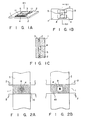
- Fig. 1A is a perspective view of the reaction vessel according to this invention
- Fig. 1B is a plan view from the direction M1 of the reaction vessel shown in Fig. 1A
- Fig. 1C is cross-section through N1 of the reaction vessel shown in Fig. 1A and Fig. 1B.
- the lower plate 1 and upper plate 3 are arranged substantially parallel on either side of 2 spacers 2.
- Lower plate 1 and upper plate 3 are both made of transparent parts, and a recess of conical shape is provided in lower plate 1.
- Part 5 surrounded by lower plate 1, upper plate 3 and the 2 spacers 2 is a sample inlet channel for introducing the sample, and it is also the reaction zone where the agglutination reaction takes place.
- the 2 sides where the spacers are not inserted constitute the sample inlet port 11, into which the sample is either injected or aspirated.
- the thickness of the spacers 2 i.e., the distance between lower plate 1 and upper plate 3, is 0.05 - 1.0 mm, and that the distance between the spacers 2 is 0.1 - 5.0 mm.
- the diameter of the conical recess 4 on lower plate 1 is 0.1 - 1.0 mm, that its depth is 0.02 - 1.0 mm, and that the angle made by 2 generators of conical recess 4 shown in Fig. 1C is 60 - 160°.
- This reaction vessel may be used to establish whether an agglutination reaction has or has not occurred. In the case where, for example, this reaction vessel is used to determine the occurrence of a reaction between blood cells and antibodies in serum, the following procedure is carried out.
- a fixed concentration of a blood cell suspension and a fixed dilution of serum are mixed in a test tube.
- the mixture is then aspirated by a pipette, and a suitable quantity is dropped to sample inlet port 11.
- the mixed solution dropped then spreads by capillarity throughout the reaction zone 5.
- the reaction vessel is allowed to stand undisturbed for a certain time, and blood cells sediment out on lower plate 1 of reaction zone 5.
- the distribution pattern of cells formed in conical recess 4 differs according to whether an antigen-antibody reaction has or has not occurred, and it is therefore possible to verify the occurrence of this reaction.
- the cells form a positive pattern 8 wherein they are spread uniformly on the sloping walls and bottom of recess 4, as shown in Fig. 2A. If on the other hand no reaction occurred and the blood cells did not agglutinate, the cells slide down the sloping walls of recess 4 to form a negative pattern 9 wherein they are concentrated in the center of the cone, as shown in Fig. 2B.
- the cells sediment uniformly, and the concentration of the blood suspension used in the reaction can therefore be measured.
- the cell distribution pattern can also be corrected based on this blood cell concentration.
- Concentric grooves may be provided on the side walls of conical recess 4 as disclosed in Japanese Patent Application No. 54-77643, but if recess 4 is sufficiently small, there is no particular need for such grooves.
- the meaning of "sufficiently small” in this context is that the diameter of recess 4 is within several hundred times the particle diameter, and if the particles are red blood cells, this corresponds to a diameter within approximately 400 ⁇ m.
- the pattern will also be small and difficult to observe with the naked eye. In this case, the pattern may be observed magnified with the aid of a lens or other device.
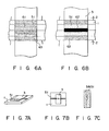
- spacers In the reaction vessel shown in Figs. 1A - 1C, rectangular spacers may be used.
- the shape of the spacers is however not limited to rectangular, and spacers such as a spacer 6 or 7 having the shapes shown in Figs. 3A - 4B may also be used. Using spacers of this shape widens the sample inlet port so that pipetting of sample becomes easier.
- the shape of recess 4 on lower plate 1 of the reaction vessel is moreover not limited to conical, and any shape may be used provided the sloping walls of the recess have a suitable angle of slope.
- An example of another possible shape is hemispherical.
- a V-shaped groove 51 may be provided instead of recess 4. with this type of reaction vessel, the pipetting of blood cell suspensions is particularly easy.
- agglutination reaction may also be established in the reaction vessel shown in Figs. 5A - 5C by the same method as is used with the reaction vessel shown in Figs. 1A - 1C. If a test is carried out to establish the occurrence or non-occurrence of a reaction of blood cells with antibodies in serum by the method described above, for example, a distribution pattern shown in Fig. 6A or 6B is obtained depending on whether the reaction took place.
- Fig. 6A is a drawing of a positive pattern 61 in the case where the particles agglutinated due particles are spread over the whole of the sloping surface of V-shaped groove 51.
- 6B is a drawing of a negative pattern 62 in the case where an antigen-antibody reaction did not occur, wherein almost all the blood cells have collected in the bottom of V-shaped groove 51. Further, the sedimented particles 63 on lower plate 1 outside V-shaped groove 51 are uniformly distributed in both cases.
- reaction vessel with a V-shaped groove on lower plate 1 may also be of the type shown in Figs. 7A - 10C.
- the reaction vessel shown in Figs. 7A - 7C is same as that in Figs. 5A - 5C excepting that the spacers 2 have been removed, and the upper plate 2 is fixed directly to the lower plate 1.
- V-shaped groove 51 also functions as the sample inlet channel. In this type of reaction vessel, it is not possible to measure the quantity of particles sedimented, and only the particle distribution pattern can be observed.
- a V-shaped groove is provided wherein the angle of slope of the sloping surface of the groove varies continuously.
- the angle of slope of the V-shaped groove varies continuously from a steep slope in part 81 of the groove, to a gentle slope in part 82 of the groove.
- the cohesive force may be measured. The particles will tend to remain on the wall surface where the slope is steeper when the cohesive force is stronger, so the more particles which have collected near part 81 of the groove, the stronger the cohesive force.
- a groove 91 of which shape is half of V-shape is provided on lower plate 1.
- a V-shaped groove 101 is provided rectangularly to the sample inlet channel.
- the groove need not necessarily be V-shaped, and may for example be U-shaped.
- reaction zone 5 need not be limited to one, and several grooves or recesses may be provided. By providing several recesses or grooves, several distribution patterns may be formed simultaneously, and the precision of measurement may thus be increased.
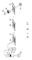
- a sample of blood is separated into a blood cell component 13 and blood serum component 12 by centrifugation or another suitable method. If the blood was treated with an anticoagulant such as hepalin, the blood serum component 12 will be plasma.
- 2 ⁇ l of the blood cell component 13 and 118 ⁇ l of a previously prepared solution 15 are mixed in a test tube 17, and initially prereacted together.
- This solution 15 consists of an anti-A serum dilution prepared by diluting standard anti-A serum (Orso Co.) to 1/30 with physiological saline.
- 5 ⁇ % of blood cell suspension 16 are pipetted by means of pipette 18 into reaction zone 5 of reaction vessel 19.
- reaction vessel wherein the distance between lower plate 1 and upper plate 3 is 80 ⁇ m, the length of the sloping wall of conical recess 4 is 500 ⁇ m, and the depth of recess 4 is 250 ⁇ m, sedimentation of all human red blood cells on the bottom of recess 4 is complete in about 10 minutes. After pipetting blood cell suspension 16, therefore, the reaction vessel is left in an incubator at 36°C for about 10 minutes.
- the reaction vessel 19 is transferred to the measurement area.
- the measurement area comprises a light source 21, and a microscope optical system 23 to observe the blood cell distribution pattern magnified, and it also has a photo sensor 24 to image the magnified blood cell distribution in the reaction zone.
- the occurrence or non-occurrence of an antigen-antibody reaction is determined by magnifying the reaction zone 5 of reaction vessel 19 by means of optical system 23, and observing the blood cell distribution pattern.
- the image obtained by photo sensor 24 may be analyzed by a computer to determine the occurrence or non-occurrence of the reaction.
- the measured blood cell distribution has a pattern of the type shown in Fig. 2A, it indicates that there are A antigens on the surface of the blood cells in the sample, and that the blood cells have agglutinated due to anti-A antibodies. If on the other hand the blood cell distribution has a pattern of the type shown in Fig. 2B, it indicates that there are no A antigens on the surface of the blood cells in the sample, and that the cells moved freely down the sloping walls of conical recess 4.
- the reactivity of the sample with respect to anti-B serum is measured in the same way, and from its measured reactivity with respect to anti-A serum and anti-B serum, the blood group of the sample can be determined. If the blood cells in the sample showed an antigen-antibody reaction with respect to both anti-A serum and anti-B serum, the blood group of the sample is AB; if there was a reaction only with respect to anti-A serum, the blood group of the sample is A; if there was a reaction only with respect to anti-B serum, the blood group of the sample is B; while if there was no reaction to either serum, the blood group of the sample is O.
- the determination of blood group which previously required 60 minutes, can be accomplished in about 10 minutes using the reaction vessel of this invention.
- a sample of blood is separated into a blood cell component 13 and blood serum component 12 by centrifugation or another suitable method. If the blood was treated with an anticoagulant such as hepalin, the blood serum component 12 will be plasma. After separation, 2 ⁇ l of the supernatant blood serum component 12 and 5 ⁇ l of a previously prepared solution 15 are mixed in a test tube 17, and initially prereacted together.
- This solution 15 consists of sensitized particles diluted to 1.0 %(v/v) with physiological saline, organically synthesized peptides having an identical amino acid sequence to HIV antigen being coated on the surface of these sensitized particles.
- the sensitized particles may consist of artificial particles of polystyrene or gelatin which have been modified chemically, animal red blood cells fixated by glutaraldehyde or the like, or similar particles.
- the antigen used to sensitize the particles may be an inactivated virus, or a recombinant protein produced by Escherichia coli or the like using gene manipulation techniques.
- the distribution of particles which have sedimented in zone 5 of reaction vessel 19 is observed using the same method as in Example 1. If the measured particle distribution gives a pattern of the type shown in Fig. 2A, it indicates that there are anti-HIV antibodies in the serum of the sample, and that the particles have agglutinated due to the anti-HIV antibodies. If on the other hand the particle distribution gives a pattern of the type shown in Fig. 2B, it indicates that there are no antibodies in the sample reacting to the surface antigens of the sensitized particles.
- an assay may be carried out for viruses or bacteria other than HIV such as HTLV-1, HB or gonococcus. Further, using antibody-sensitized particles, an assay for antigen may be carried out for HBs, drugs or cancer markers. Further, if particles of several different colors are made to combine respectively with different antibodies or antigens, and for example a color CCD camera is used as photo sensor 24, assays for several antibodies or antigens may be carried out in one operation.
- an assay can be carried out in 10 min using the reaction vessel of this invention. Moreover, the assay may be performed using less of the costly particle reagent than was previously required.
- an antiserum with respect to A antigens on the surface of blood cells is coated in the recess 4 of a reaction vessel as shown in Figs. 1A - 1C using the method described below.
- Standard anti-A serum (Orso Co.) is diluted to 1/10 with 10 mM Tris-HCl buffer solution, pH 9, containing 0.15M NaCl. 2 ⁇ lof the diluted solution is dropped to reaction zone 5 arranged on the polyethylene lower plate 1. After dropping, the diluted solution is incubated at 37°C for 1 hour while maintaining humid conditions so that it does not dry out. The reaction zone 5 is then washed by dropping 1 ⁇ l of 10 mM phosphate buffer solution, ph 7.2, containing 0.15M NaCl.
- reaction zone 5 After removing the wash solution by gently shaking lower plate 1, 1 ml of 10 mM phosphate buffer solution, pH 7.2, containing 3% (w/v) of bovine serum albumin and 0.15 M NaClare dropped in around reaction zone 5, and the lower plate is incubated at room temperature while maintaining humid conditions for 1 hour. By this procedure, the area of the reaction zone which adsorbs blood cells nonspecifically is blocked. After incubation reaction zone 5 is again washed using 2 ml of 10 mM phosphate buffer solution, pH 7.2, containing 0.15 M NaCl. If the lower plate is to be kept for a long period, 0.02% (w/v) NaN3 is added to the final wash solution, and the lower plate is kept at 4°C after washing.
- upper plate 3 is also treated so that non-specific reaction with blood cells does not occur. This is done by leaving the upper plate 3 at room temperature for 1 hour in 10 mM phosphate buffer solution, pH 7.2, containing 3% (w/v) bovine serum albumin and 0.15 M NaCl ⁇ cand washing it with 10 mM phosphate buffer solution, pH 7.2, containing 0.15 M NaCl. If the upper plate is to be left for a long period, 0.02% (w/v) NaN3 is added to the final wash solution, and the upper plate is kept at 4°C as in the case of the lower plate.
- the reaction vessel is assembled using 2 spacers 2 which are fixed by means of double-sided adhesive tape or adhesive.
- a sample of blood is separated into a blood cell component 13 and blood serum component 12 by centrifugation or another suitable method. If the blood was treated with an anticoagulant such as hepalin, the blood serum component 12 will be plasma.
- 2 ⁇ l of the sedimented blood cell component 13 and 198 ⁇ l of a solution 14 are mixed in a test tube 17 to prepare a 1% blood cell suspension.
- solution 14 is physiological saline.
- This blood cell suspension 16 is then introduced by means of a pipette 18 to reaction zone 5 of reaction vessel 19 wherein anti-A serum has been coated as described above. After pipetting, the vessel is incubated at about 36°C for 10 min, care being taken not to shake the vessel.
- the distribution pattern of particles sedimented in reaction zone 5 of reaction vessel 19 is observed using the same method as in Example 1. If there are A antigens on the surface of the blood cells in the sample, the cells combine with the anti-A serum that was coated in the reaction vessel, and the blood cells are uniformly distributed practically all over reaction zone 5 including recess 4. The pattern which appears in this case is therefore of the type shown in Fig. 2A. If on the other hand there are no A antigens on the surface of the cells in the sample, the blood cells do not combine with the anti-A serum coated in the reaction vessel, and the cells move freely down the sloping walls of conical recess 4. In this case, therefore, the distribution of blood cells gives a pattern of the type shown in Fig. 2B.
- the presence or absence of B antigens on the surface of the blood cells may be determined in the same way by measuring the reactivity of the sample with respect to anti-B serum.
- the blood group of the sample can be determined. If the blood cells in the sample showed an antigen-antibody reaction with respect to both anti-A serum and anti-B serum, the blood group of the sample is AB; if there was a reaction only with respect to anti-A serum, the blood group of the sample is A; if there was a reaction only with respect to anti-B serum, the blood group of the sample is B; while if there was no reaction to either serum, the blood group of the sample is O.
- the determination of blood group which previously required 60 minutes, can be accomplished in about 10 minutes using the reaction vessel of this invention.
- HIV antigens are coated in the reaction zone 5 of the reaction vessel.
- the HIV antigens coated in the reaction vessel may be chemically synthesized HIV virus surface antigens, HIV recombinant proteins produced by Escherichia coli, or the HIV virus itself.
- a sample of blood is separated into a blood cell component 13 and blood serum component 12 by centrifugation or another suitable method. If the blood was treated with an anticoagulant such as hepalin, the blood serum component 12 will be plasma. 2 ulof the serum component obtained was removed in a test-tube 17, then 18 ⁇ l of physiological saline was added and mixed with it. 5 ⁇ l of this diluted serum solution 26 was pipetted by means of pipette 18 to a reaction vessel 19 wherein HIV antigens had been coated. After pipetting, the reaction vessel was incubated at 37°C for 2 min (27).
- an anticoagulant such as hepalin
- reaction zone 5 Following the reaction, physiological saline for washing was introduced by nozzle 28 into reaction zone 5 of reaction vessel 19, and waste liquid was aspirated simultaneously by nozzle 29 from the opposite side.
- the reaction zone 5 can be washed, and the serum component which did not react with the antigen coated in reaction vessel 19 can be washed out.
- the anti-human antibodies used here may also be monoclonal antibodies derived from mouse or the like, or a substance such as protein A which binds to antibodies.
- the particles on which the antibodies are coated may be red blood cells fixated by glutaraldehyde or the like, or synthetic particles such as polystyrene.
- the particle distribution is observed by the same method as that of Example 1. If there are antibodies against for HIV in the serum of the sample, they combine with the HIV antigens coated in the reaction vessel, and the particles to which anti-human antibodies have been coated combine with the antibodies which have combined with the antigens. The particle distribution is therefore of the type shown in Fig. 2A. If on the other hand there are no HIv antibodies in the serum of the sample, the particles roll freely down the sloping walls of recess 4 of the reaction vessel without causing any reaction. The particle distribution is therefore of the type shown in Fig. 2B.
- antibodies against for viruses other than HIV such as HTLv-1 or HTLv-II or for bacteria may also be detected.
- the antibody usually has 2 - 10 antigen binding sites. Particles to which the same antigen has been coated as the antigen coated in the reaction vessel, may therefore also be used as particle reagent 31.
Landscapes
- Health & Medical Sciences (AREA)
- Chemical & Material Sciences (AREA)
- Immunology (AREA)
- Life Sciences & Earth Sciences (AREA)
- Hematology (AREA)
- Engineering & Computer Science (AREA)
- Biomedical Technology (AREA)
- Urology & Nephrology (AREA)
- Analytical Chemistry (AREA)
- General Health & Medical Sciences (AREA)
- Molecular Biology (AREA)
- Biotechnology (AREA)
- Medicinal Chemistry (AREA)
- Cell Biology (AREA)
- Microbiology (AREA)
- Clinical Laboratory Science (AREA)
- Dispersion Chemistry (AREA)
- Food Science & Technology (AREA)
- Chemical Kinetics & Catalysis (AREA)
- Physics & Mathematics (AREA)
- Biochemistry (AREA)
- General Physics & Mathematics (AREA)
- Pathology (AREA)
- Investigating Or Analysing Biological Materials (AREA)
- Automatic Analysis And Handling Materials Therefor (AREA)
- Devices For Use In Laboratory Experiments (AREA)
Applications Claiming Priority (2)
| Application Number | Priority Date | Filing Date | Title |
|---|---|---|---|
| US457289 | 1989-12-27 | ||
| US07/457,289 US5066465A (en) | 1989-12-27 | 1989-12-27 | Reaction apparatus |
Publications (3)
| Publication Number | Publication Date |
|---|---|
| EP0435246A2 true EP0435246A2 (de) | 1991-07-03 |
| EP0435246A3 EP0435246A3 (en) | 1992-02-19 |
| EP0435246B1 EP0435246B1 (de) | 1995-08-09 |
Family
ID=23816151
Family Applications (1)
| Application Number | Title | Priority Date | Filing Date |
|---|---|---|---|
| EP90125481A Expired - Lifetime EP0435246B1 (de) | 1989-12-27 | 1990-12-24 | Reaktionsgefäss |
Country Status (4)
| Country | Link |
|---|---|
| US (1) | US5066465A (de) |
| EP (1) | EP0435246B1 (de) |
| JP (1) | JPH04145947A (de) |
| DE (1) | DE69021529T2 (de) |
Cited By (6)
| Publication number | Priority date | Publication date | Assignee | Title |
|---|---|---|---|---|
| US7033747B2 (en) | 2001-04-11 | 2006-04-25 | Nagaoka & Co., Ltd | Multi-parameter assays including analysis discs and methods relating thereto |
| US7054258B2 (en) | 2000-12-08 | 2006-05-30 | Nagaoka & Co., Ltd. | Optical disc assemblies for performing assays |
| US7079468B2 (en) | 2000-12-08 | 2006-07-18 | Burstein Technologies, Inc. | Optical discs for measuring analytes |
| US7387898B1 (en) | 1996-10-08 | 2008-06-17 | Burstein Technologies, Inc. | Apparatus and method for conducting assays |
| EP2290358A3 (de) * | 2001-07-27 | 2012-02-29 | ARKRAY, Inc. | Analyseinstrument |
| CN113976192A (zh) * | 2021-08-23 | 2022-01-28 | 上海荧辉医疗器械有限公司 | 微球标记微流控芯片以及微球蛋白标记方法 |
Families Citing this family (23)
| Publication number | Priority date | Publication date | Assignee | Title |
|---|---|---|---|---|
| US5188968A (en) * | 1989-12-28 | 1993-02-23 | Olympus Optical Co., Ltd. | Method and reaction kit for agglutination detection |
| JP3382632B2 (ja) * | 1992-03-13 | 2003-03-04 | オリンパス光学工業株式会社 | 生体関連物質の測定方法およびそれに用いる反応容器 |
| FI923220A7 (fi) * | 1992-07-14 | 1994-01-15 | Wallac Oy | Menetelmä ja laitteisto näytteen käsittelemiseksi sekä näytteenkeräysjärjestelmä |
| DE19941905C2 (de) * | 1999-09-02 | 2002-06-06 | Max Planck Gesellschaft | Probenkammer zur Flüssigkeitsbehandlung biologischer Proben |
| JP2002286721A (ja) * | 2001-03-22 | 2002-10-03 | Olympus Optical Co Ltd | 凝集反応分析容器 |
| JP2002286722A (ja) * | 2001-03-22 | 2002-10-03 | Olympus Optical Co Ltd | 凝集反応分析装置 |
| JP2002286719A (ja) * | 2001-03-23 | 2002-10-03 | Olympus Optical Co Ltd | 複数のパラメータを用いて凝集反応を解析評価する方法およびその方法に用いる容器 |
| US7323139B2 (en) * | 2002-07-26 | 2008-01-29 | Quantum Design, Inc. | Accessible assay and method of use |
| CA2532414C (en) | 2003-07-12 | 2017-03-14 | Accelr8 Technology Corporation | Sensitive and rapid biodetection |
| US20120077206A1 (en) | 2003-07-12 | 2012-03-29 | Accelr8 Technology Corporation | Rapid Microbial Detection and Antimicrobial Susceptibility Testing |
| SE528638C2 (sv) * | 2005-04-08 | 2007-01-09 | Boule Medical Ab | Anordning för fyllning av en enhet för bestämning av en provvolym |
| EP1878497A1 (de) * | 2006-07-14 | 2008-01-16 | Roche Diagnostics GmbH | Einwegartikel zur Analyse einer flüssigen probe durch Vervielfältigung von Nukleinsäuren |
| US20080280310A1 (en) * | 2007-05-09 | 2008-11-13 | Louis Panagopoulos | Testing for Blood Group Immunological Reaction Without the Use of Anti-Human Globulin |
| JP4976586B2 (ja) * | 2008-04-02 | 2012-07-18 | アボット ポイント オブ ケア インコーポレイテッド | 構成成分アッセイにおける自己較正勾配希釈及び薄膜状試料において実施される勾配希釈装置 |
| US10254204B2 (en) | 2011-03-07 | 2019-04-09 | Accelerate Diagnostics, Inc. | Membrane-assisted purification |
| ES2551922T3 (es) | 2011-03-07 | 2015-11-24 | Accelerate Diagnostics, Inc. | Sistemas rápidos de purificación celular |
| US9389229B2 (en) | 2012-07-18 | 2016-07-12 | Theranos, Inc. | Methods for detecting and measuring aggregation |
| US9677109B2 (en) | 2013-03-15 | 2017-06-13 | Accelerate Diagnostics, Inc. | Rapid determination of microbial growth and antimicrobial susceptibility |
| US10252231B2 (en) | 2014-10-31 | 2019-04-09 | Massachusetts Institute Of Technology | Compositions and methods for forming emulsions |
| US10253355B2 (en) | 2015-03-30 | 2019-04-09 | Accelerate Diagnostics, Inc. | Instrument and system for rapid microorganism identification and antimicrobial agent susceptibility testing |
| KR20170132856A (ko) | 2015-03-30 | 2017-12-04 | 액셀러레이트 다이어그노스틱스, 아이엔씨. | 신속한 미생물 동정 및 항균제 감수성 시험을 위한 기기 및 시스템 |
| US20190170737A1 (en) | 2016-09-19 | 2019-06-06 | Massachusetts Institute Of Technology | Systems including janus droplets |
| US12274993B2 (en) | 2019-09-18 | 2025-04-15 | Massachusetts Institute Of Technology | Systems and methods for affecting interactions of electromagnetic radiation with janus droplets for sensitive detection of species |
Family Cites Families (11)
| Publication number | Priority date | Publication date | Assignee | Title |
|---|---|---|---|---|
| JPS561352A (en) * | 1979-06-20 | 1981-01-09 | Olympus Optical Co Ltd | Container for corpuscular cohesion judgement |
| US4323536A (en) * | 1980-02-06 | 1982-04-06 | Eastman Kodak Company | Multi-analyte test device |
| US4426451A (en) * | 1981-01-28 | 1984-01-17 | Eastman Kodak Company | Multi-zoned reaction vessel having pressure-actuatable control means between zones |
| US4427781A (en) * | 1981-03-16 | 1984-01-24 | International Institute Of Cellular And Molecular Pathology | Particle agglutination immunoassay with agglutinator for determining haptens; PACIA |
| JPS5821141A (ja) * | 1981-07-30 | 1983-02-07 | Olympus Optical Co Ltd | 粒子凝集反応判定方法および判定容器 |
| US4608246A (en) * | 1983-03-10 | 1986-08-26 | Immucor, Inc. | Testing for a blood group immunological reaction |
| JPS6086468A (ja) * | 1983-10-18 | 1985-05-16 | Olympus Optical Co Ltd | 抗原抗体反応の判定方法 |
| JPS6144268A (ja) * | 1984-08-09 | 1986-03-03 | 松下電器産業株式会社 | エンジン駆動ヒ−トポンプ装置 |
| US4596695A (en) * | 1984-09-10 | 1986-06-24 | Cottingham Hugh V | Agglutinographic reaction chamber |
| US4756884A (en) * | 1985-08-05 | 1988-07-12 | Biotrack, Inc. | Capillary flow device |
| EP0321736B1 (de) * | 1987-12-23 | 1994-06-01 | Abbott Laboratories | Vorrichtung zur Agglutinierungsreaktion |
-
1989
- 1989-12-27 US US07/457,289 patent/US5066465A/en not_active Expired - Lifetime
-
1990
- 1990-12-24 DE DE69021529T patent/DE69021529T2/de not_active Expired - Lifetime
- 1990-12-24 EP EP90125481A patent/EP0435246B1/de not_active Expired - Lifetime
- 1990-12-27 JP JP2418979A patent/JPH04145947A/ja not_active Withdrawn
Cited By (13)
| Publication number | Priority date | Publication date | Assignee | Title |
|---|---|---|---|---|
| US7387898B1 (en) | 1996-10-08 | 2008-06-17 | Burstein Technologies, Inc. | Apparatus and method for conducting assays |
| US7542383B2 (en) | 2000-12-08 | 2009-06-02 | Vindur Technologies, Inc. | Optical disc assemblies for performing assays |
| US7079468B2 (en) | 2000-12-08 | 2006-07-18 | Burstein Technologies, Inc. | Optical discs for measuring analytes |
| US7200100B2 (en) | 2000-12-08 | 2007-04-03 | Nagaoka & Co., Ltd. | Optical disc assemblies for performing assays |
| US7366063B2 (en) | 2000-12-08 | 2008-04-29 | Burstein Technologies, Inc. | Optical discs for measuring analytes |
| US7054258B2 (en) | 2000-12-08 | 2006-05-30 | Nagaoka & Co., Ltd. | Optical disc assemblies for performing assays |
| US7599275B2 (en) | 2000-12-08 | 2009-10-06 | Vindur Technologies, Inc. | Optical discs for measuring analytes |
| US7889615B2 (en) | 2000-12-08 | 2011-02-15 | Vindur Technologies, Inc. | Optical discs for measuring analytes |
| US7033747B2 (en) | 2001-04-11 | 2006-04-25 | Nagaoka & Co., Ltd | Multi-parameter assays including analysis discs and methods relating thereto |
| EP2290358A3 (de) * | 2001-07-27 | 2012-02-29 | ARKRAY, Inc. | Analyseinstrument |
| US8425841B2 (en) | 2001-07-27 | 2013-04-23 | Arkray, Inc. | Analyzing instrument |
| CN113976192A (zh) * | 2021-08-23 | 2022-01-28 | 上海荧辉医疗器械有限公司 | 微球标记微流控芯片以及微球蛋白标记方法 |
| CN113976192B (zh) * | 2021-08-23 | 2023-08-15 | 上海汉原生物科技有限公司 | 微球标记微流控芯片以及微球蛋白标记方法 |
Also Published As
| Publication number | Publication date |
|---|---|
| DE69021529D1 (de) | 1995-09-14 |
| DE69021529T2 (de) | 1996-04-18 |
| EP0435246B1 (de) | 1995-08-09 |
| US5066465A (en) | 1991-11-19 |
| JPH04145947A (ja) | 1992-05-19 |
| EP0435246A3 (en) | 1992-02-19 |
Similar Documents
| Publication | Publication Date | Title |
|---|---|---|
| EP0435246B1 (de) | Reaktionsgefäss | |
| US5188968A (en) | Method and reaction kit for agglutination detection | |
| US4303616A (en) | Agglutination analyzing vessel | |
| US5219763A (en) | Agglutination method for the determination of multiple ligands | |
| US20040166551A1 (en) | Detection of agglutination of assays | |
| JPH087215B2 (ja) | 抗原および/又は抗体の検出方法および検出用の試験キット | |
| US5283178A (en) | Method of forming agglutinates in blood samples | |
| JP2009098138A (ja) | 高感度免疫測定方法 | |
| US20200333336A1 (en) | Immunochromatography device | |
| EP0435245B1 (de) | Reaktionskit | |
| JPH08201391A (ja) | マ−カ−粒子を用いた免疫学的測定方法 | |
| JPH09229936A (ja) | 磁性粒子を用いる被検物質の測定方法並びに該方法に使用する担体及び測定器具 | |
| JP2614997B2 (ja) | 凝集反応のための反応促進装置 | |
| CA2938935C (en) | Crossmatching blood samples | |
| KR101798428B1 (ko) | 면역 분석 장치 및 그 사용 방법 | |
| US20050130223A1 (en) | Method, system and kit for detecting an analyte in a sample | |
| JP2716227B2 (ja) | 磁性マーカー粒子を用いた免疫学的測定方法 | |
| JP2000131320A (ja) | 特異的結合物質固定粒子を用いる被検物質の測定方法 | |
| JPH10132819A (ja) | 粒子を用いる被検物質の測定方法及び該方法に使用する測定器具 | |
| JPH03191864A (ja) | 間接凝集免疫測定方法及び装置 | |
| JP2009085703A (ja) | 高感度免疫測定方法 | |
| US6500673B1 (en) | Electrostatic device and method for immunological detection | |
| JPH01131459A (ja) | 間接凝集反応容器及びそれを用いた凝集素の測定方法 | |
| JPH11287803A (ja) | 粒子を使用する被検物質の測定器具及び測定方法 |
Legal Events
| Date | Code | Title | Description |
|---|---|---|---|
| PUAI | Public reference made under article 153(3) epc to a published international application that has entered the european phase |
Free format text: ORIGINAL CODE: 0009012 |
|
| 17P | Request for examination filed |
Effective date: 19901224 |
|
| AK | Designated contracting states |
Kind code of ref document: A2 Designated state(s): DE FR GB |
|
| PUAL | Search report despatched |
Free format text: ORIGINAL CODE: 0009013 |
|
| AK | Designated contracting states |
Kind code of ref document: A3 Designated state(s): DE FR GB |
|
| 17Q | First examination report despatched |
Effective date: 19930315 |
|
| GRAA | (expected) grant |
Free format text: ORIGINAL CODE: 0009210 |
|
| AK | Designated contracting states |
Kind code of ref document: B1 Designated state(s): DE FR GB |
|
| REF | Corresponds to: |
Ref document number: 69021529 Country of ref document: DE Date of ref document: 19950914 |
|
| ET | Fr: translation filed | ||
| PLBE | No opposition filed within time limit |
Free format text: ORIGINAL CODE: 0009261 |
|
| STAA | Information on the status of an ep patent application or granted ep patent |
Free format text: STATUS: NO OPPOSITION FILED WITHIN TIME LIMIT |
|
| 26N | No opposition filed | ||
| REG | Reference to a national code |
Ref country code: GB Ref legal event code: IF02 |
|
| REG | Reference to a national code |
Ref country code: FR Ref legal event code: CD |
|
| PGFP | Annual fee paid to national office [announced via postgrant information from national office to epo] |
Ref country code: FR Payment date: 20100106 Year of fee payment: 20 Ref country code: GB Payment date: 20091229 Year of fee payment: 20 |
|
| PGFP | Annual fee paid to national office [announced via postgrant information from national office to epo] |
Ref country code: DE Payment date: 20091230 Year of fee payment: 20 |
|
| REG | Reference to a national code |
Ref country code: GB Ref legal event code: 732E Free format text: REGISTERED BETWEEN 20100812 AND 20100818 |
|
| REG | Reference to a national code |
Ref country code: GB Ref legal event code: PE20 Expiry date: 20101223 |
|
| PG25 | Lapsed in a contracting state [announced via postgrant information from national office to epo] |
Ref country code: GB Free format text: LAPSE BECAUSE OF EXPIRATION OF PROTECTION Effective date: 20101223 |
|
| PG25 | Lapsed in a contracting state [announced via postgrant information from national office to epo] |
Ref country code: DE Free format text: LAPSE BECAUSE OF EXPIRATION OF PROTECTION Effective date: 20101224 |