EP0435429A1 - Verfahren und Vorrichtung zur gleichzeitigen Messung der Winkel- und Axialposition - Google Patents
Verfahren und Vorrichtung zur gleichzeitigen Messung der Winkel- und Axialposition Download PDFInfo
- Publication number
- EP0435429A1 EP0435429A1 EP90310941A EP90310941A EP0435429A1 EP 0435429 A1 EP0435429 A1 EP 0435429A1 EP 90310941 A EP90310941 A EP 90310941A EP 90310941 A EP90310941 A EP 90310941A EP 0435429 A1 EP0435429 A1 EP 0435429A1
- Authority
- EP
- European Patent Office
- Prior art keywords
- electrodes
- sensing
- signal
- parts
- signals
- Prior art date
- Legal status (The legal status is an assumption and is not a legal conclusion. Google has not performed a legal analysis and makes no representation as to the accuracy of the status listed.)
- Granted
Links
- 238000000034 method Methods 0.000 title claims abstract description 21
- 238000006073 displacement reaction Methods 0.000 claims abstract description 34
- 230000008878 coupling Effects 0.000 claims abstract description 10
- 238000010168 coupling process Methods 0.000 claims abstract description 10
- 238000005859 coupling reaction Methods 0.000 claims abstract description 10
- 238000012545 processing Methods 0.000 claims description 2
- 238000001514 detection method Methods 0.000 claims 2
- 238000005191 phase separation Methods 0.000 claims 1
- 238000005259 measurement Methods 0.000 description 38
- 238000010586 diagram Methods 0.000 description 21
- 239000003990 capacitor Substances 0.000 description 11
- 230000005540 biological transmission Effects 0.000 description 9
- 239000004020 conductor Substances 0.000 description 6
- 238000012937 correction Methods 0.000 description 5
- 239000000463 material Substances 0.000 description 5
- 230000000737 periodic effect Effects 0.000 description 5
- 238000013461 design Methods 0.000 description 4
- 238000009413 insulation Methods 0.000 description 4
- RYGMFSIKBFXOCR-UHFFFAOYSA-N Copper Chemical compound [Cu] RYGMFSIKBFXOCR-UHFFFAOYSA-N 0.000 description 3
- 230000010354 integration Effects 0.000 description 3
- 239000000853 adhesive Substances 0.000 description 2
- 230000001070 adhesive effect Effects 0.000 description 2
- 239000000872 buffer Substances 0.000 description 2
- 239000011889 copper foil Substances 0.000 description 2
- 230000000694 effects Effects 0.000 description 2
- 230000007613 environmental effect Effects 0.000 description 2
- 230000008569 process Effects 0.000 description 2
- 230000000087 stabilizing effect Effects 0.000 description 2
- 238000012546 transfer Methods 0.000 description 2
- UUTKICFRNVKFRG-WDSKDSINSA-N (4R)-3-[oxo-[(2S)-5-oxo-2-pyrrolidinyl]methyl]-4-thiazolidinecarboxylic acid Chemical compound OC(=O)[C@@H]1CSCN1C(=O)[C@H]1NC(=O)CC1 UUTKICFRNVKFRG-WDSKDSINSA-N 0.000 description 1
- -1 Polytetrafluoroethylene Polymers 0.000 description 1
- 230000008901 benefit Effects 0.000 description 1
- 238000004364 calculation method Methods 0.000 description 1
- 230000008859 change Effects 0.000 description 1
- 239000011248 coating agent Substances 0.000 description 1
- 238000000576 coating method Methods 0.000 description 1
- 239000012141 concentrate Substances 0.000 description 1
- 229910052802 copper Inorganic materials 0.000 description 1
- 239000010949 copper Substances 0.000 description 1
- 238000009795 derivation Methods 0.000 description 1
- 238000011161 development Methods 0.000 description 1
- 238000005516 engineering process Methods 0.000 description 1
- 239000000284 extract Substances 0.000 description 1
- 238000001914 filtration Methods 0.000 description 1
- 239000011888 foil Substances 0.000 description 1
- 230000014509 gene expression Effects 0.000 description 1
- 238000009499 grossing Methods 0.000 description 1
- 230000005283 ground state Effects 0.000 description 1
- 238000012886 linear function Methods 0.000 description 1
- 238000000691 measurement method Methods 0.000 description 1
- 238000012986 modification Methods 0.000 description 1
- 230000004048 modification Effects 0.000 description 1
- 230000003287 optical effect Effects 0.000 description 1
- 230000010363 phase shift Effects 0.000 description 1
- 239000002985 plastic film Substances 0.000 description 1
- 229920006255 plastic film Polymers 0.000 description 1
- 229920001343 polytetrafluoroethylene Polymers 0.000 description 1
- 239000004810 polytetrafluoroethylene Substances 0.000 description 1
- 230000000717 retained effect Effects 0.000 description 1
- 238000005096 rolling process Methods 0.000 description 1
- 230000006641 stabilisation Effects 0.000 description 1
- 238000011105 stabilization Methods 0.000 description 1
- 230000001052 transient effect Effects 0.000 description 1
- 230000007704 transition Effects 0.000 description 1
Images






Classifications
-
- G—PHYSICS
- G01—MEASURING; TESTING
- G01D—MEASURING NOT SPECIALLY ADAPTED FOR A SPECIFIC VARIABLE; ARRANGEMENTS FOR MEASURING TWO OR MORE VARIABLES NOT COVERED IN A SINGLE OTHER SUBCLASS; TARIFF METERING APPARATUS; MEASURING OR TESTING NOT OTHERWISE PROVIDED FOR
- G01D5/00—Mechanical means for transferring the output of a sensing member; Means for converting the output of a sensing member to another variable where the form or nature of the sensing member does not constrain the means for converting; Transducers not specially adapted for a specific variable
- G01D5/12—Mechanical means for transferring the output of a sensing member; Means for converting the output of a sensing member to another variable where the form or nature of the sensing member does not constrain the means for converting; Transducers not specially adapted for a specific variable using electric or magnetic means
- G01D5/14—Mechanical means for transferring the output of a sensing member; Means for converting the output of a sensing member to another variable where the form or nature of the sensing member does not constrain the means for converting; Transducers not specially adapted for a specific variable using electric or magnetic means influencing the magnitude of a current or voltage
- G01D5/24—Mechanical means for transferring the output of a sensing member; Means for converting the output of a sensing member to another variable where the form or nature of the sensing member does not constrain the means for converting; Transducers not specially adapted for a specific variable using electric or magnetic means influencing the magnitude of a current or voltage by varying capacitance
- G01D5/241—Mechanical means for transferring the output of a sensing member; Means for converting the output of a sensing member to another variable where the form or nature of the sensing member does not constrain the means for converting; Transducers not specially adapted for a specific variable using electric or magnetic means influencing the magnitude of a current or voltage by varying capacitance by relative movement of capacitor electrodes
- G01D5/2412—Mechanical means for transferring the output of a sensing member; Means for converting the output of a sensing member to another variable where the form or nature of the sensing member does not constrain the means for converting; Transducers not specially adapted for a specific variable using electric or magnetic means influencing the magnitude of a current or voltage by varying capacitance by relative movement of capacitor electrodes by varying overlap
- G01D5/2415—Mechanical means for transferring the output of a sensing member; Means for converting the output of a sensing member to another variable where the form or nature of the sensing member does not constrain the means for converting; Transducers not specially adapted for a specific variable using electric or magnetic means influencing the magnitude of a current or voltage by varying capacitance by relative movement of capacitor electrodes by varying overlap adapted for encoders
Definitions
- This invention pertains to position sensors, particularity to sensors of angular and axial position. With still greater particularity the invention pertains to the simultaneous sensing of both the angular and axial position of a collar on a shaft by capacitive means.
- the simplest sensor would be a mechanical linkage from the part sought to be monitored to a dial. Such sensors become generally impractical where the area where the information is needed is a distance from the part being monitored.
- Such sensors include potentiometer, magnetic pickups of various types, optical pickups, and capacitive pickups.
- the pickups are generally potentiometer or resolvers.
- the property being measured is angular position.
- a mechanical linkage is often provided to convert the longitudinal position into an angular position.
- a sensor specially adapted to sense longitudinal position is provided.
- the senor In applications such as inside a drive train or engine the sensor must be capable of working this environment for extended periods of time at elevated temperatures and pressures. It is also desirable if the sensor can function as a bearing between the two parts. Accordingly there is a need for a sensor that can provide information about both the angular and axial relative position of two parts while functions as a bearing.
- the invention provides a sensor which is capable of sensing both angular and axial position of a collar to a shaft. There is no need to reposition the sensor to measure the separate factors.
- the sensor is capable of operating in motors and drivetrains.
- the sensor is also capable of functioning as a bearing while acting as a sensor.
- the sensor includes a plurality of electrodes attached to the outer circumference of the shaft. These electrodes are insulated from one another and the shaft. Electrical connections are provided to the set electrodes. A second set of electrodes are provided on the inner surface of the collar. Optionally, electrical connections may be provided to this second set of electrodes.
- An electronic package is provided to provide proper electrical signals to each set of electrodes and to sense the output from the appropriate set of electrodes. The electronic package is further capable of multiplexing the signals and decoding the signals.
- a alternating current signal is applied to one half of the electrodes on the shaft denominated as the transmitting electrodes.
- the other half of the electrodes on the shaft the receiving electrodes are connected to the input of an amplifier.
- the signal is conveyed from the transmitting electrodes to the receiving electrodes by capacitive coupling via the electrodes on the collar.
- the amount of signal conveyed is proportional to the position of the collar on the shaft. This relationship is fixed by the geometric configuration of the two sets of electrodes. This configuration may be varied to sense different amounts of rotation and provide greater accuracy.
- Figure 1 is an environmental view of the sensor of the invention.
- a slider 2 is movable relative to an axle 1.
- Slider 2 is movable both axially and angularly relative to axis 1.
- bearing surface 3 is selected from materials having both a low coefficient of friction and wearing properties.
- bearing surface 3 should be electrically insulating.
- Polytetrafluoroethylene film has been found to be a suitable material for surface 3 but other materials having similar properties as outlined above could be substituted.
- Electrodes 4 may be constructed by using a plastic film 7 with a copper coating which is etched by printed circuit technology to form any desired pattern. Common Flexible Printed Circuit material (FPC) can be used for films. The film 7 with attached electrodes 4 is then rolled around axle 1 and fixed with an adhesive.
- FPC Flexible Printed Circuit material
- Electrodes 8 may be formed of copper foil directly in the outer surface of bearing surface 3. This may be easily accomplished by attached copper foil to bearing film material by use of a suitable adhesive. Undesired portions of the foil are then etched away. The resulting electrodes 8 may be formed in any desired pattern. The film with attached electrodes is then rolled and attached to collar 2. Electrodes 8 may be provided with electrical connections 11 in some applications.
- electrodes 4 and 8 are capacitively coupled.
- either the angular or axial position of slider 2 on axle 1 may be determined.
- Fundamental to understanding of the invention is the fact that the inducement of charge in a capacitor is proportional to the capacitance which in turn is proportional to the area of electrodes separated by a dielectric.
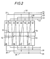
- Figure 2 is a plan view of the electrodes attached to axis 1 before rolling.
- the pattern of electrodes illustrated is desirable for simultaneous measurement of limited angular position and axial position.
- each set consists of two electrodes.
- the number of electrodes in each set will vary dependant upon the size of axle 1 and the degree of accuracy and angular range desired. This embodiment is designed for an angular range of approximately 40 degrees.
- the first set of electrodes 21 and 22 are triangular in shape, they are electrically connected together by conductor 23 and are connected at terminal 24 (A1).
- the second set of electrodes 26 and 27 are triangular in shape, they are electrically connected together by conductor 28 and are connected at terminal 29 (A2).
- the third set of electrodes 31 and 32 are triangular in shape, they are electrically connected together by conductor 33 and are connected at terminal 34 (C1).
- the fourth set of electrodes 36 and 37 are triangular in shape, they are electrically connected together by conductor 38 and are connected at terminal 39 (C2). Electrodes 21, 22, 26, 27,31,32,36, and 38 all function as transmitters in this embodiment of the invention.
- the fifth set of electrodes 41 and 42 are rectangular in shape, they are electrically connected together by conductor 43 and are connected at terminal 44 (B).
- the sixth set of electrodes 46 and 47 are rectangular in shape, they are electrically connected together by conductor 48 and are connected at terminal 49 (D). Electrodes 41, 42,46 and 47 all function as receivers in this embodiment of the invention.
- the slider also has four electrodes 51,52,53 and 54.
- the slider electrodes are rectangular in shape and without electrical connections. Electrodes 51-54 are separate and electrically isolated. Electrodes 51-54 are capacitively coupled to the electrodes on axle 1.
- transmitting electrodes 21,22,31 and 32 are all connected together. Similarly, transmitting electrodes 26,27,36 and 37 are connected together. The result is two sets of transmitting electrodes. A source of alternating current is connected between the two sets of electrodes this results on a charge being imposed on electrodes 21,22,31, and 32 that is 180 degrees out of phase with that imposed on electrodes 26,27,36 and 37. Similarly all receiving electrodes 41,42,46 and 47 are connected in parallel.
- Electrodes 21 and 26 divide a rectangular area by the diagonal split between them.
- the voltages on electrodes 21 and 26 in turn induce a charge in the adjacent capacitively coupled slider electrode 51.
- This charge will vary in magnitude dependant upon the position of slider 2 on axle 1 due to the diagonal split between electrodes 21 and 26. For example if slider 2 is on one end 56 of axle 1 the charge induced will predominantly that opposite of the charge on electrode 21. This is because the area of electrode 21 under electrode 51 is much larger than that of electrode 26. The opposite is true if slider 2 is on the opposite end 57 of axle 1.
- Cx2 C1*(1-x/L)
- the capacitance from the collar electrodes to the receiving plates 41+42+46+47 is constant, independent of the collar position relative to the axle. Lets design its value with C2.
- connections to the electrodes are rearranged. In this embodiment that function is accomplished by the phasing of signals applied to the electrode as described below with the description of the multiplexing system of the invention.
- Electrodes 21 and 22 are connected in parallel with electrodes 26 and 27 to form two rectangular transmitting electrodes and are connected to a source of alternating current.
- electrodes 31 and 32 are connected in parallel with electrodes 37 and 38 to form a second set of rectangular transmitting electrodes. Electrodes 31,32,37,and 38 are connected to a source of alternating current that is 180 degrees out of phase with that connected to electrodes 21,22,26, and 27. This completes the connections to the transmitting portion of the angular displacement sensor.
- Rectangular receiving electrodes 41 and 42 are connected to the + input of a differential amplifier.
- Rectangular receiving electrodes 46 and 47 are connected to the - input of the differential amplifier. This completes the receiving portion of the angular displacement sensor.
- the width of the slider electrodes 51-54 is selected to be twice the period length in angular direction, that which the rectangular pattern on the axis is repeated.
- Each 21/26. 31/36, etc electrode is considered as equal elements in determining that periodicity.
- the tapered portion of electrodes 21/26, 31/36, etc. is disabled by feeding conjugant 21/26, 22/27, ...) tapered electrodes with the same signal. Every other of those electrodes are fed with opposite polarity signal, so 21/26 and 22/27 are fed with one signal from the oscillator, while electrodes 31/36 and 32/37 are fed with signal of opposite polarity.
- the receiving electrodes 41+42 and 46+47 are separately connected to the electronic unit. The collar electrodes placed so their dividing lines are over the 41,46,42,47 electrodes while moving of the collar within the measuring range.
- the capacitance between electrode-pair 21/26 and the collar electrode 51 is the constant over the angular measuring range. Name it C1.
- C2 the capacitance at full overlap 45 is the angle for full overlap in this embodiment
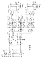
- Figure 3 is a schematic diagram of the transmitter timing package of the invention.
- Three operational amplifiers 101,102, and 103 are connected to form an oscillator.
- the frequency is determined by the values of two resistors 104 and 105 and a capacitor 106.
- HC 04 operational amplifiers have been shown to be successful when 104 and 105 have values of 33,000 and 39,000 ohms respectively and 106 has a value of 100 pico farads to produce an output frequency of about 25khz.
- the output of the oscillator is conveyed to the input of a flip-flop 107.
- Flip-flop 107 halves the output of the oscillator and allows timing.
- Output 108 of flip-flop 107 is applied directly to transmitting electrodes 21 and 22.
- a HC 74 integrated circuit has been found satisfactory for flip-flop 107.
- a reset switch 109 is connected to the reset input of flip-flop 107 by way of a buffer amplifier 111. The result is a pulse on electrodes 21 and 22 on every other pulse produced by the oscillator.
- a phase selection switch 110 is provided to allow selection of phase.
- the output of the oscillator also is connected to the input of a decade counter 112.
- Decade counter is a five stage johnson decade counter with a built in code converter.
- a MC14017B decade counter made by Motorola has been found suitable although other equivalent counters could be substituted.
- Counter 112 provides an output of terminal 113 on input of the first pulse terminal 114 on the second and so through terminal 120 on the eight pulse.
- the reset terminal 121 of counter 112 is further connected to the reset switch 109. When reset switch 109 is closed a voltage is imposed on the reset terminals of both flip-flop 107 and counter 112 ensuring that each of their cycles will begin on the leading edge of the next pulse from the oscillator.
- Outputs 114,116 and 119 of counter 112 are connected to the input of a Nor gate 123.
- the output of Nor gate 123 is connected to the input of an invertor 124.
- the output of invertor 124 is connected to electrodes 31 and 32 of the encoder. The result is a pulse on electrodes 31 and 32 on each second, forth and seventh pulse produced by the oscillator.
- Outputs 113,116 and 120 of counter 112 are connected to the input of a second Nor gate 126.
- the output of Nor gate 126 is connected to the input of an invertor 127.
- the output of inverter 127 is connected to electrodes 26 and 27 of the encoder. The result is a pulse on electrodes 26 and 27 on each first, forth and eighth pulse produced by the oscillator.
- Outputs 113,116 and 119 of counter 112 are connected to the input of a third Nor gate 128.
- the output of Nor gate 128 is connected to the input of an invertor 129.
- the output of invertor 129 is connected to electrodes 36 and 37 of the encoder. The result is a pulse on electrodes 36 and 37 on each first, forth and seventh pulse produced by the oscillator.
- Each output of counter 112 is also connected to an analog switch.
- two DG308A quad Monolithic spst switch manufactured by Siliconix has been found satisfactory. The result is that switch 140 is closed on the first pulse, 141 on the second pulse and so through switch 147 which is closed on the eighth pulse.
- Figure 4 is a series of waveforms which illustrate the timing of the system.
- the first waveform 151 is the timing pulses of the oscillator.
- the output 152 of flip-flop 107 which is applied to transmitting electrodes 21 and 22 which produces a pulse on every other oscillator pulse.
- Third is the output 153 of invertor 124 which is applied to transmitter electrodes 31 and 32. This output is a pulse on each second, fourth, and seventh oscillator pulse.
- Forth is the output 154 of invertor 127 which is applied to transmitter electrodes 26 and 27. This output is a pulse on each first, fourth, and eight oscillator pulse.
- Fifth, is the output 155 of invertor 129 which is applied to transmitter electrodes 36 and 37. This output is a pulse on each first,forth and seventh oscillator pulse.
- Waveforms 161-166 are the periods during which switches 140-147 are closed.
- switch 140 is closed 161 during the period during which transmitting electrodes 26,27,36 and 37 are receiving signals.
- switch 141 is closed 162 during the period in which transmitting electrodes 21,22,31 and 32 are receiving signals.
- Switch 143 is closed 163 during the ground state at which time no transmitting electrode is receiving signals.
- Switch 144 is closed 164 during a period where all transmitting electrodes are receiving a signal.
- Switch 145 is closed during the period 165 when transmitting electrodes 31,32,36 and 37 are receiving a signal. Finally, switch 146 is closed during the period when transmitting electrodes 21,22,26 and 27 are receiving a signal. These two switches are thus closed when the encoder is configured to produce a angular displacement signal.
- FIG. 5 is a schematic diagram of the receiver of the invention.
- One input 151 is connected to the receiving electrodes 41,and 42 similarly receiving electrodes 46 and 47 are connected to input 152.
- Each input is connected to a charge amplifier.
- the charge amplifier connected to input 151 includes an operational amplifier 153 a capacitor 154 and a resistor 156.
- Operational amplifier 153 has one input connected to ground.
- a charge amplifier provides at output that is proportional to the ratio of the capacitance an input 151 and capacitor 154.
- a 347 operational amplifier has been found to be satisfactory when capacitor 154 is 20pf.
- a similar charge amplifier including an operational amplifier 157, capacitor 159 and resistance 155 is connected to input 152.
- the outputs of the charge amplifiers are connected by way of 10k ohm resistors 160 and 165 to the + input of another operational amplifier 161.
- the - input is grounded.
- Amplifier 161 thus produces a signal at output 162 that is the sum of the signals outputed from amplifiers 153 and 157.
- a resistance 163 provides stability when selected to provide negative feedback. 10 K ohms has been found satisfactory for 163.
- the outputs of one charge amplifier is connected by way of 10k ohm resistor 170 to the - input of another operational amplifier 171.
- the + input is connected by way of resistor 175 to the other charge amplifier.
- Amplifier 171 thus produces a signal at output 172 that is the difference of the signals outputed by amplifiers 153 and 157.
- a resistance 173 provides stability. 10 K ohms has been found satisfactory for 173.
- demodulator sections consisting of the operational amplifiers 181, 191, 201 and surrounding components. The configurations of each section are identical. Two of the demodulators operate on the sum signal at terminal 162. The other demodulator operates on the difference signal at terminal 172.
- the first demodulator includes an operational amplifier 181.
- Two integration capacitances 182 and 183 are connected to its inputs.
- Resistances 184,185,186 and 187 aid in isolating signals. Values of 22k ohms for 184 and 185 and 10k ohms for 186 and 187 have been found effective with use of a 347 operational amplifier.
- Switch 141 is connected in series with the + input of operational amplifier 181 and switch 140 is connected in series with the - input.
- the first demodulator produces a negatively integrated signal at output 188 when a signal is applied to transmitting electrodes 26,27,36 and 37 when switch 140 is closed and a positively integrated signal at output 188 when a signal is applied to electrodes 21,22,31 and 32 when switch 141 is closed.
- the output at terminal 188 is thus the average of the signal transferred through plates 21+22+31+32 to plates 41+42-46-47 via the plates 51+52+53+54 on the collar, which signal is proportional to the transverse displacement of collar 2 on axle 1.
- the second demodulator includes an operational amplifier 191.
- Two integration capacitances 192 and 193 are connected to its inputs. Resistances 194,195,196 and 197 aid in isolating signals and stabilizing DC levels. Values of 22k ohms for 194 and 195 and 10k ohms for 196 and 197 have been found effective with use of a 347 operational amplifier.
- Switch 142 is connected in series with the + input of operational amplifier 191 and switch 143 is connected in series with the - input. As a result the second demodulator produces a negatively integrated signal at output 198 when a signal is applied to all transmitting electrodes 21,22,31,32,26,27,36 and 27 when switch 143 is closed.
- the second demodulator When switch 142 is closed, the second demodulator produces a positive integrated output of the voltage out form 162, for the case of no signals connected to the transmitting plates, which serves to balance the output for existing DC signals in the preceding electronic circuits.
- the sum output at terminal 198 is thus representing the signal amplitude from the sensor, independent of the axial and angular movement. This signal is used to normalize the signals for angular and axial measurement and thereby make the measurements independent on variations of the input signal amplitude and variations of the gap between the plates on the axle and the plates on the collar.
- the third demodulator includes an operational amplifier 201.
- Two integration capacitances 202 and 203 are connected to its inputs.
- Resistances 204,205,206 and 207 aid in isolating signals and stabilizing DC levels. Values of 22k ohms for 204 and 205 and 10k ohms for 206 and 207 have been found effective with use of a 347 operational amplifier.
- Switch 147 is connected in series with the + input of operational amplifier 201 and switch 146 is connected in series with the - input.
- the third demodulator produces a negatively integrated signal at output 208 when a signal is applied to transmitting electrodes 21,32,36 and 37 when switch 146 is closed and then a positively integrated signal when a signal is applied to electrodes 21,22,26 and 27 when switch 147 is closed.
- the output at terminal 208 is thus proportional to the angular displacement of slider 2 on axle 1.
- the result of the demodulator process is a longitudinal signal at point 188 and an angular signal at point 208 and finally, a correction signal at point 198.
- the longitudinal and angular signals must be divided by the correction signal to produce a corrected output. This is accomplished by use of two divider circuits. In this embodiment two internally trimmed integrated circuit dividers 211 and 222 were used. A circuit manufactured by Analog Devices under the part number AD535 has been found successful in this embodiment.
- the longitudinal signal at 188 is connected to the numerator input 210 of 211 and the correction signal at 198 to the denominator input 213.
- the product output 212 is connected to a trimmer potentiometer 214 and the output 215.
- the angular signal at 208 is applied to the nominator input 219 of divider 212 and the correction signal at 198 to the denominator input 220.
- the product output 216 is in turn connected through a trimmer potentiometer 217 to output 218.
- the signal at output 215 is a DC voltage which is proportional to the longitudinal displacement of slider 2 on axle 1.
- the signal at output 218 is also a DC voltage which is proportional to the angular displacement of slider 2 on axle 1.
- a variety of output devices may be connected to outputs 215 and 216 including but not limited to meters, oscilloscopes and a analog to digital converter if digital readout is desired.
- Figure 6 is a plan view of the encoder electrodes of a second embodiment of the invention.
- connections are required both to the collar and the axle,
- This embodiment has the advantage that the signal is stronger than that of the figure 2 embodiment as there is only one capacitance in series for each transmission path.
- the device is shown unrolled for clarity but in practice would be used as shown in figure 1.
- Electrodes 301,303,305 and 307 are connected together to form group 317.
- Electrodes 302,304,306 and 308 are connected together to form group 318.
- Electrodes 309,311,313 and 315 are connected together to form group 319.
- Electrodes 310,312,314 and 316 are connected together to form group 320. This completes the transmitting electrodes.
- receiving electrodes 321-328 There are 8 receiving electrodes 321-328 connected to collar 2. Each receiving electrode is rectangular. Electrodes 321,323,325 and 327 are connected to form group 329. Similarly, electrodes 322,324,326 and 328 are connected together to form group 330.
- an alternating current signal having the value of cos wt is placed on the electrodes in groups 317 and 318.
- a second signal having the value of sin wt that is 90 degrees out of phase with the first signal is placed on the electrodes in groups 319 and 320.
- the sum of the signals received on the electrodes in groups 329 and 330 will follow the equation x cos wt + j(1-x) sin wt where x is the axial displacement w is the angular velocity and t is time. This signal may easily be decoded by conventional electronic circuitry to isolate x.
- an alternating current signal having the value of cos wt is placed on the electrodes in groups 318 and 320.
- a second signal having the value of sin wt that is 90 degrees out of phase with the first signal is placed on the electrodes in groups 319 and 317.
- the difference of the signals received on the electrodes in groups 329 and 330 will follow the equation (1 + (angle/45)) cos wt - j(angle/45) sin wt where x is the axial displacement w is the angular velocity and t is time.
- This signal may easily be decoded by conventional electronic circuitry to isolate the angle.
- the above signals may be multiplexed in the manner illustrated in the description of figures 4 and 5 to allow simultaneous measurement of both the axial and angular displacement.
- Figures 7 to Fig 16 illustrate a third embodiment of the invention, suited for measurement over extended range both in the linear and angular direction.
- the linear measurement can be extended over any desired measurement range, with retained ability to resolve the finest increment of measurement.
- the angular range can be extended to the full 360 degree rotation of the hub, or even with counting of the revolutions, function over several revolutions. Provisions are also made for getting an absolute indication of position in both directions, in spite of the primary measurements being basically incremental in counting measurement periods as will be further explained hereinbelow.
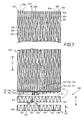
- FIG. 7 is a plan view of the unfolded electrode pattern for this embodiment wherein 501 is the wrapped-out pattern for attachment to axle 1, and 502 is the wrapped-out pattern for attachment to collar 2.
- Axle pattern 501 includes a number of longitudinal sections 503 and 504, where each section has a constant tangential width and is extended along axle 1 on the surface of the axle. Sections 503 and 504 are alternating so every second section is of the same kind. Each section 503 is internally divided into three fields 505, 506, 507, in a way that forms a periodic pattern along the axle. Each section has an extension in tangential direction, that follows a sinusoidal function, with the three sections being phaseshifted relative to each other by 360/3 degrees.
- A(505) A + B*sin(2* ⁇ *x/L1)
- A(506) A + B*sin(2* ⁇ *x/L1-2* ⁇ /3)
- A(507) A + B*sin(2* ⁇ *x/L1+2* ⁇ /3)
- P1(x) K
- P2(x) K + A(505)
- P3(x) K + A(505) + A(506)
- the value of the constant B is chosen to be a little less than A, enough for A-B to form a continuous conducting path for each subsection 505, 506, 507 along the pattern through the narrow portions.
- the distance La is the wavelength for fine angular measurement. Furthermore, the connections to the electronics from the electrodes on the axle are done in two groups (T11, T12, T13, T21, T22, T23) and (T31, T32, T33, T41, T42, T43), so the electrodes can be fed in a manner that constitutes one period of signals over the full 360 degree circumference of the axle.
- the pattern of electrodes for attachment to collar 2 includes two rings of electrodes 511 and 512.
- Ring 511 is divided into three sections 513, 514, 515.
- Ring 512 is also divided into three sections 516, 517, 518.
- Each section is in turn divided into two parts by a sinusoidal shaped insulation space 519 - 524.
- the insulation spaces are chosen to have a wavelength equal to the axle tangential wavelength La, expressed as an angle.
- the three sections on each ring 511 and 512 have their sinusoidal functions phaseshifted by 360/3 degrees, and between the two rings, the sections are offset by 180 degrees.
- the resulting electrode pattern on the collar thus contains 6 phases for Fine angular measurement, by utilizing the electrodes in the La wavelength pattern, and 6 phases for Coarse angular measurement by combining the electrodes in the 2*3 sections of the electrode rings.
- the two rings have a width and distance between them, that is adapted to the axial wavelength L1 and L2 on the axle pattern, so they can function as receiver for that wavelength.
- the width w is preferably not more than half of L1 or L2 and the distance d between the rings is preferable an odd multiple of (L1+L2)/4.
- a practical dimensioning makes the width less than half of the mean value of L1 and L2, so the two rings can be placed at half the mean value of L1 and L2.
- each of the electrodes 513-518 to the electronic unit is done with each of the electrodes on the collar brought out as a separate connection as on the axle pattern.
- the electrodes are given names for this description as follows:
- each 503 section On axle 1, the three electrodes 505-507 in each 503 section are connected to the corresponding electrodes in the other 503 sections over half of the circumference of the axle, making three connections T11, T12, T13 to the electronics.
- the remaining 503 sections are connected similarly forming three connections T31, T32, T33.
- the 504 sections are connected in a corresponding way making the terminals T21, T22, T23 from the first half of the axle circumference and T41, T42, T43 from the second half of the axle circumference.
- Figure 8 is a block diagram of the electronic unit for the figure 7 embodiment.
- the terminals to the transducer are connected in several combinations through multiplexing, for achieving information about the relative position between axle and collar in both axial and angular direction, both Fine and Coarse measurement in both directions.
- Figures 9 to 12 illustrate the four different modes of connection of electrodes to the electronics package.
- Figure 9 shows the connection for axial measurement ring the L1 wavelength scales.
- the terminals T11, T12, and T13 are parallel connected to terminals T31, T32, and T33 in numerical order, and the resulting three input terminals are connected to a three-phase output signal R,S,T in the electronics.
- the collar electrodes are connected with all electrodes from the first ring together, resulting in a ring-shaped electrode, the signal of which is connected to the negative terminal of the Analogue Receiving Block (ARB)551.
- the terminals from the second ring are similarly connected together to form a second ring electrode, the signal of which is connected to the positive terminal of the ARB 551.
- Fig 10 illustrates the connection for axial measurement using the L2 wavelength scales.
- the terminals T21, T22, and T23 are parallel connected to terminals T41, T42, and T43 in numerical order, and the resulting three input terminals are connected to a three-phase output signal in the electronics.
- the collar electrodes are connected in the same manner as illustrated in figure 9 when measuring with wavelength L1.
- the measurement with wavelength L1 gives the position within the Fine wavelength L1.
- the measurement with the wavelength L2 gives the same type of information, but because of the wavelength difference, there is a difference between these two measurements, proportional to the number of L1 (L2) wavelengths that the collar is displaced from the zero point along the axle.
- the information about Coarse position within the Coarse range Lc is obtained by subtracting the measurement value at L1 measurement from the measurement value at L2 measurement.
- Xc (x1-x2)*Lc/L1 Where Xc represents the coarse position, x1 and x2 represent the Fine position within a L1 wavelength, x2 the Fine position within a L2 wavelength.
- FIG 11 illustrates the connections for angular Fine measurement.
- the axle pattern is connected with sections 503 connected to the positive side of the signal generator 553, sections 504 connected to the negative side of the signal generator 553.
- a periodic field pattern is formed in the angular direction with angular wavelength La.
- This pattern is sensed by the collar electrodes by having the electrodes connected in a manner that constitutes a six-phase sensor with an effective wavelength equal to the axle angular wavelength La.
- electrode terminal R11 is parallel with terminal R21 giving the first phase
- electrode terminal R12 is parallel with terminal R22 giving the second phase and so on.
- the receiver By scanning over the six phases by a switch network, the receiver receives a signal, the envelope of which has a phase position that is proportional to the angular position of the collar relative to the axle within the angular wavelength La.
- the position within this wavelength can this way be measured to within a fraction of the wavelength, practically to within 1/100 to 1/1000 of the wavelength, limited by the accuracy of the pattern and the dimensioning of the electronic circuit.
- Figure 12 illustrates the connections for the angular Coarse measurement.
- the axle electrodes are grouped with all electrodes on one half of the circumference (T11, T12, T13, T21, T22, T23) connected to one side of the transmitted signal 554, the electrodes on the other half of axle 1 (T31, T32, T33, T41, T42, T43) connected to the other polarity of transmitter signal 554.
- the connections are grouped for making a six-phase receiver with a wavelength equal to 360 degrees of the axle circumference.
- electrode terminals R11 and R14 are connected together for forming the first receiver phase
- electrode terminals R22 and R25 are connected together for forming the second receiver phase
- the oscillator 601 is providing clock signals for the whole thing, as well as modulation signals for the transmitter.
- the clock signal is in unit 602 divided by a factor N, which in this embodiment in 96, but can be of higher value for higher resolution of the interpolation within the respective wavelengths.
- the outputs from the divider 602 are combined in the logical network 607 for giving transmitter signals T11, T12, T13, T21, T22, T23, T31, T32, T33, T41, T42, T43 to the electrode groups on the axle.
- Those signals are amplified in the buffers 608 for driving the transducer with low impedance signals.
- the logical network 607 also provides input signals A, B, CLOCK, R, S, T, to the switch controller 609.
- the switch network 610 combines the output terminals from the receiver electrodes 513-518 (the collar) for the four measuring modes in a multiplexing fashion in sync with the corresponding multiplexing on the transmitter side. Both the transmitter multiplexing and the receiver multiplexing will be further described in connection with the timing diagram of figure 15 and the detailed diagram of the switch network of fig 13.
- Analogue Receiving Blocks (ARB)611-614, one of each of the four functional modes of the sensor: ARB(611) for Fine1, ARB(612) for Fine2, ARB(613) for AngularFine, and ARB(614) for AngularCoarse.
- the outputs from these blocks (611 - 614) are square waves of the same frequency as the signals R,S,T (at zero moving speed), and the phase position of each of those square waves is essentially proportional to the mechanical position of collar 2 relative to the electrode pattern on axle 1 within the actual wavelength for each of the measuring modes.
- Latch2 604 will give a digital representation of the axial position within the wavelength L2
- Latch3 606 will give a digital representation of angular position within a Fine angular wavelength La
- Latch 4 606 will give a digital representation of the coarse angular position within 360 degrees.
- microprocessor 616 The outputs from the four latches 603-606 is read from the microprocessor 616 via the port 615 microprocessor 616 is programmed by conventional means to calculate the actual absolute position and transform them to a suitable form to be received by external equipment.
- the methods for reading the data from the latches and combining them and converting them to the desired output format are well known by electrical engineers, familiar with microprocessors and their programming.
- ⁇ dm*3/8 giving the axial position value out: x nf*11/dm.
- ⁇ dm*3/8 giving the angular axial position in degree value out: A Af*360/dm+K The microprocessor then ends the process.
- Fig 15 illustrates a number of important waveforms in the system according to fig 102.
- the "clock" 651 signal is produced by oscillator 601.
- Signals A 652 and B 653 are the first steps in binary dividing the clock signal to lower frequencies.
- the multiplexing sequence "xFine1 654, xFine2 655 , aFine 656, and a Coarse 657 " can be defined.
- the lines 654-657 with those four names in the timing diagram indicate with the horizontal bars the time intervals that are assigned for respective function.
- the signals R 658, S 659 , and T 660 are the modulation signals for the three phases to the transmitter in the axial measuring mode, as well as the "scanning" signals for the receiver in the angular measuring mode.
- the signals to the transmitter electrodes T11 661, T12 662, T13 663, T21 664, T22 665, T23 666, T31 667, T32 668, T33 669, T41 670, T42 671, and T43 672 are assigned the same names in the timing diagram.
- the transducer is capacitive, the information transfer occurs only in the voltage transitions. Therefore, in the design of this system we can concentrate our attention on the voltage transients in the signals.
- the receiver switching is designed for letting through the transients that are coincident with the negative flanks of the clock signals (see Swx1 673, Swx2 674, SwaF 675, SwaC 676), while the positive flank is grounded (SwG 677). Therefore only the part of the transmitter signals that are coincident with the negative flanks of the clock signal are of interest in designing the waveforms for the transmitters. With this in mind it is easy to see that the effect of the transmitter waveforms according to T11, T12, T13, T21, T22, T23, T31, T32, T33, T41, T42, T43 diagrams in fig 115 will be that the transmitter electrodes are multiplexed between the configuration according to figures 9 through 12.
- FIG 13 is a detailed diagram of the Switch Network 610 from figure8. All the switch symbols represent CMOS switches, which can easily be integrated into a custom IC chip, whereby the great number of switches will not cause any problem for signal load or required space.
- the switches 705 are closed and the axial measurements are done.
- Switches 701 are activated during the Fine1 mode, with a closed interval that surrounds the negative transmission time of the clock signal. For safe functioning, this gate signal is created with a clock signal that is slightly offset relative to the original clock signal. This is easily done with a simple time delay network, familiar to an electrical engineer, skilled in the art of design of digital circuits.
- Switches 702 are activated in the Fine2 mode and their gate signals Swx2 are designed to surround the negative transmission of the clock signal the same way as the 701 gate signal. This characteristic of surrounding the corresponding edge of the clock signal is also valid for the angular gate signals SwaF and SwaC (negative clock transmission) as well as the grounding clock signal SwG (positive clock transmissions).
- the outputs 701 are two wires, in the block diagram represented by one wire. The same comments holds for each of the outputs 702, 703 and 704. Those two wires represent differential inputs to the Analogue Receiving Blocks 611, 612, 613, 614 respectively, as will be more apparent from figure 14, which is a detailed representation of a solution for those blocks.
- the switches 707 and 708 make the appropriate interconnections between receiving electrodes for angularCoarse and angularFine modes respectively.
- six receiving phases PH1....PH6 are created, and they are scanned by switches 709 for forming differential output signals for terminal pairs 703 and 704 for the angularFine resp angularCoarse measurements.
- the 707 switches are closed during the aCoarse intervals according to the timing diagram, and the 708 switches are closed during the aFine intervals.
- the SwaF and SwaC switches are closed around the appropriate negative clock transmissions intervals according to the timing diagram and we get the desired demodulation of the receiver signals into the appropriate ARB.
- the switches 710 Surrounding the positive transmission intervals of the clock signal, the switches 710 are closed, controlled by the signal SwG as seen in the timing diagram. This will connect the charges in transmission during the positive clock transmission to groung.
- Figure 14 illustrates a typical Analogue Receiving Block of the invention.
- the input signals 801 and 802 are connected to the inputs of a charge amplifier 803.
- Charge amplifier 803 includes two capacitors 804 and 804 and an operational amplifier 806. In this configuration the output at point 807 is proportional to the difference between the ratios of the capacitive loads at inputs 801 and 802 to the values of capacitances 805 and 804 respectively.
- Low pass filter 808 The output of charge amplifier 807 is connected to a low pass filter 808.
- Filter 808 in this embodiment is an active filter including an operational amplifier 809 and appropriate resistances 810 811 and 812 and capacitor 813. Design of active low pass filters is well established and no further elaboration is necessary.
- Low pass filter 808 functions as a phase detector.
- the analogue receiving block consists of a charge amplifier 803, a low-pass filter 808 and a comparator 814.
- the charge amplifier inputs 801 and 802 are via the previous described switch network connected to the receiver electrodes in the transducer, which have a source impedance that is capacitive.
- the voltage transients from the input of the transducer are transformed to voltage transients on the output of operational amplifier 806 with an amplitude that is proportional to the ratio of the coupling capacitance through the transducer to the feedback capacitors 805 and 804.
- For DC stabilization of the amplifier output there are also a resistor of very high value parallel to each of the capacitors 805 and 804. those resistors are not shown in the fig 14.
- the signal 807 on the output of is shown in the timing diagram of fig 15 for two different position of angular movement 807a and 807b.
- the phase position of this signal is proportional to the mechanical position of the collar electrode pattern relative to the axis electrode pattern.
- the signal 807 is High pass filtered by the network 820-819, serving to eliminate any DC voltage existing on the amplifier output.
- the filter 808 consists of an operational amplifier 809 with connected resistors and capacitors, dimensioned to function as a low pass filter with the purpose of smoothing out the staircase waveform on signal 807 to be more continuous without any steep transients.
- the thus obtained waveform on output of the amplifier 809 is illustrated in fig 15.
- the waveform is illustrated for two angular positions under number 822a and 822b respectively. The location of the zero crossings of these waveforms represent the mechanical position.
- the signal 822 is via the high-pass filter 821/818 transferred to the comparator circuit 814. It contains the comparator 816 with the resistors 817 and 818 connecting its input terminals to a suitable bias level.
- the output from comparator 816 will be a square wave with its flanks coincident with the zero crossings of the 822 signal.
- the square wave output from each of the four analogue receiving blocks 611-614 (fig 8) is then triggering each one its latch for getting a digital representation of the phaseshift and thereby the mechanical position for each channel.
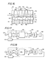
- Fig 16 shows an embodiment of the invention where only the collar electrodes have galvanic connection to the electronics.
- freefloating electrodes 901-908 configured the same way as the transmitter electrodes in the figure 2 embodiment.
- On the collar are an array of rectangular electrodes 910-917 connected in two groups, every second to the same group, with output terminals C and D.
- two ring electrodes,921 and 922 are two on each side of the 910-917 array. Output terminals for these two ring electrodes are A and B.
- the capacitance between ring electrode 921 and electrode 901 is equal to a constant times the axial displacement plus the distance between 921 and 910.
- the capacitance between ring electrode 922 and electrode 901 is equal to a constant times the axial displacement minus the distance between 921 and 910.
- the capacitance between ring electrode 921 and electrode 902 is equal to a constant times 1 minus the axial displacement minus the distance between 921 and 910.
- the capacitance between ring electrode 922 and electrode 902 is equal to a constant times 1 minus the axial displacement plus the distance between 921 and 910.
- the capacitance between electrode 910 and electrode 901 is equal to a constant times the axial displacement.
- the capacitance between electrode 910 and electrode 902 is equal to a constant times 1 minus the axial displacement.
- the signal delivered between C and D when a signal is inputed to A and B is equal to the signal at A times the axial displacement plus the distance between the ring and center electrodes divided by three added to the signal on B times one minus the axial displacement minus the distance between the ring and center electrodes.
- the signal is directly proportional to the axil displacement. Similar calculations apply to angular displacements.
- Terminal A is fed with a signal sinus(wt) while the B terminal is fed with cosinus(wt).
- terminals C+D in parallel we will then get a signal, whose phase position relative to the input signals is a one to one function of the axial position.
- Terminals C and D are fed with cosinus and sinus signals respectively, and terminals A+B are in parallel connected to the receiver input of the electronics.
- the phase of the received signal will have a one to one relation to the angular position within a limited range (max 45 degrees for the illustrated embodiment with four periods of pattern around the circumference.
- the electronics in figures 17 and 18 include an oscillator 923, a frequency divider and sin/cos synthesizer 924, a receiver amplifier 926, a filter 927 a comparator 928, and a latch 929.
- the transducer is 925.
- the Frequency divider divides the clock frequency by for instance 256, which number is dimensioning for the rate of resolution that can be achieved in the measurement.
- the sin and cos signal can be created by a digital sin or cos synthesizer from the binary data in the divider, but it is also possible to use quadrature square waves of the lowest frequency out from the divider if we have a suitable filtering in the filter 927 of the receiver side for extracting the fundamental component out of the received signal.
- the low frequency sin/cos signals are modulated by the clock frequency for obtaining a high frequency signal through the transducer.
- the received signal is demodulated and amplified in unit 926 and a low frequency waveform is obtained.
- the filter 927 extracts the harmonic component out of this signal and a clean signal with information of the position embedded in its phase angle relative to the transmitting LF signal is obtained.
- the comparator 928 the zero-crossings of the sine wave is detected and a square wave is created. This square wave is triggering the latch 929 and a digital representation of the position is obtained.
- the two functions represented by figures 17 and 18 can be multiplexed with the help of Cmos switches as described in other embodiments of the invention and simultaneous indication of both angular and axial position can be obtained.
- the multiplexing is preferable done at a high frequency relative to the LF modulation for the filters to be subject to a continuous signal of the detected frequency. This also means that the receiving section has to be separate for each measuring channel, but the transmitting section can be multiplexed.
- the role of the transmitter and receiver plates can be reversed, with appropriate modification of the electronic unit.
- the information about position in both directions is contained in the capacitance couplings between the electrode groups, which can be measured with various means, including standard capacitance measuring instruments, and the so obtained values can be utilized for calculating the mechanical position.
- the shapes of the electrode plates can, within the invention idea, be varied for obtaining a desired nonlinear function for the output signals representing the position in the two directions, or for adapting to different signal processing means.
- the sinsoidial function for the capacitance that is desirable for measuring over long absolute range with the phase measurement method described in one of above embodiments, can be approximated with rectangular electrodes placed in a periodic pattern (an array) in the measurement direction.
- the pattern on the collar can be extended in the axial direction over longer distance than illustrated above, with several rings of electrodes making a periodic pattern in the axial direction. In such a case, a multiphase receiver for the axial measurement direction is an option.
- the collar electrodes can also be simplified to be only one electrode ring also in the multiperiod version of figure 7.
Landscapes
- Engineering & Computer Science (AREA)
- Power Engineering (AREA)
- Physics & Mathematics (AREA)
- General Physics & Mathematics (AREA)
- Measurement Of Length, Angles, Or The Like Using Electric Or Magnetic Means (AREA)
- Transmission And Conversion Of Sensor Element Output (AREA)
Applications Claiming Priority (2)
| Application Number | Priority Date | Filing Date | Title |
|---|---|---|---|
| US41959689A | 1989-10-10 | 1989-10-10 | |
| US419596 | 1989-10-10 |
Publications (2)
| Publication Number | Publication Date |
|---|---|
| EP0435429A1 true EP0435429A1 (de) | 1991-07-03 |
| EP0435429B1 EP0435429B1 (de) | 1994-11-30 |
Family
ID=23662928
Family Applications (1)
| Application Number | Title | Priority Date | Filing Date |
|---|---|---|---|
| EP90310941A Expired - Lifetime EP0435429B1 (de) | 1989-10-10 | 1990-10-05 | Verfahren und Vorrichtung zur gleichzeitigen Messung der Winkel- und Axialposition |
Country Status (3)
| Country | Link |
|---|---|
| EP (1) | EP0435429B1 (de) |
| JP (1) | JP2530252B2 (de) |
| DE (1) | DE69014577T2 (de) |
Cited By (10)
| Publication number | Priority date | Publication date | Assignee | Title |
|---|---|---|---|---|
| US5414420A (en) * | 1992-03-23 | 1995-05-09 | Hewlett-Packard Corporation | Switch interconnect for position encoder system |
| US5416479A (en) * | 1992-03-23 | 1995-05-16 | Hewlett-Packard Corporation | Handle for position encoder system |
| US5428355A (en) * | 1992-03-23 | 1995-06-27 | Hewlett-Packard Corporation | Position encoder system |
| EP0648998A3 (de) * | 1993-10-19 | 1996-02-07 | Hans Ulrich Meyer | Instrument zum Messen der Längen oder Winkel. |
| EP0747673A1 (de) | 1995-06-07 | 1996-12-11 | Tesa Brown & Sharpe S.A. | Kapazitive Messvorrichtung |
| DE19944203A1 (de) * | 1999-09-15 | 2001-03-22 | Zahnradfabrik Friedrichshafen | Vorrichtung zum Erfassen einer Stellung eines Stellelements |
| US6346818B2 (en) | 1998-07-22 | 2002-02-12 | British Aerospace Plc | Capacitance position transducer |
| EP1774258A4 (de) * | 2004-06-23 | 2008-12-17 | Fe Technical Services Inc | Kapazitive messtechniken |
| EP3104128A1 (de) * | 2015-06-12 | 2016-12-14 | Sick Ag | Vorrichtung zur kontaktlosen übertragung von daten und zur ermittlung einer winkeländerung zwischen zwei sich relativ zueinander bewegenden gegenständen |
| CN107003154A (zh) * | 2014-12-17 | 2017-08-01 | 东方马达股份有限公司 | 静电编码器 |
Families Citing this family (3)
| Publication number | Priority date | Publication date | Assignee | Title |
|---|---|---|---|---|
| DE10066138B4 (de) * | 1999-03-30 | 2004-09-23 | Dr. Johannes Heidenhain Gmbh | Verfahren und Schaltungsanordnung zur Korrektur von periodischen Signalen eines inkrementalen Positionsmesssystems |
| EP1166047B1 (de) | 1999-03-30 | 2003-06-11 | Dr. Johannes Heidenhain GmbH | Verfahren und schaltungsanordnung zur korrektur von periodischen signalen eines inkrementalen positionsmesssystems |
| FR3052250B1 (fr) * | 2016-06-06 | 2020-05-01 | Continental Automotive France | Dispositif de mesure de position angulaire d'un arbre ou similaire |
Citations (5)
| Publication number | Priority date | Publication date | Assignee | Title |
|---|---|---|---|---|
| GB2060173A (en) * | 1979-09-25 | 1981-04-29 | Fiat Ricerche | Capacitive transducer with six degrees of freedom |
| EP0065625A2 (de) * | 1981-05-07 | 1982-12-01 | International Business Machines Corporation | Kapazitiver Winkelmessgeber |
| EP0248165A2 (de) * | 1986-04-04 | 1987-12-09 | Mitutoyo Corporation | Transduktor vom kapazitiven Typ für Lagemessungen |
| EP0258725A2 (de) * | 1986-09-02 | 1988-03-09 | Hengstler GmbH | Kapazitiver Drehgeber zum Steuern und Positionieren von bewegten Gegenständen |
| EP0184584B1 (de) * | 1983-11-11 | 1991-09-25 | Mauser-Werke Oberndorf GmbH | Kapazitive Längen- und Winkelmesseinrichtung |
Family Cites Families (1)
| Publication number | Priority date | Publication date | Assignee | Title |
|---|---|---|---|---|
| JPS61213605A (ja) * | 1985-03-19 | 1986-09-22 | Mitsutoyo Mfg Co Ltd | 静電容量型デジタルノギス |
-
1990
- 1990-10-05 DE DE69014577T patent/DE69014577T2/de not_active Expired - Fee Related
- 1990-10-05 EP EP90310941A patent/EP0435429B1/de not_active Expired - Lifetime
- 1990-10-08 JP JP2269980A patent/JP2530252B2/ja not_active Expired - Lifetime
Patent Citations (5)
| Publication number | Priority date | Publication date | Assignee | Title |
|---|---|---|---|---|
| GB2060173A (en) * | 1979-09-25 | 1981-04-29 | Fiat Ricerche | Capacitive transducer with six degrees of freedom |
| EP0065625A2 (de) * | 1981-05-07 | 1982-12-01 | International Business Machines Corporation | Kapazitiver Winkelmessgeber |
| EP0184584B1 (de) * | 1983-11-11 | 1991-09-25 | Mauser-Werke Oberndorf GmbH | Kapazitive Längen- und Winkelmesseinrichtung |
| EP0248165A2 (de) * | 1986-04-04 | 1987-12-09 | Mitutoyo Corporation | Transduktor vom kapazitiven Typ für Lagemessungen |
| EP0258725A2 (de) * | 1986-09-02 | 1988-03-09 | Hengstler GmbH | Kapazitiver Drehgeber zum Steuern und Positionieren von bewegten Gegenständen |
Cited By (18)
| Publication number | Priority date | Publication date | Assignee | Title |
|---|---|---|---|---|
| US5414420A (en) * | 1992-03-23 | 1995-05-09 | Hewlett-Packard Corporation | Switch interconnect for position encoder system |
| US5416479A (en) * | 1992-03-23 | 1995-05-16 | Hewlett-Packard Corporation | Handle for position encoder system |
| US5428355A (en) * | 1992-03-23 | 1995-06-27 | Hewlett-Packard Corporation | Position encoder system |
| EP0648998A3 (de) * | 1993-10-19 | 1996-02-07 | Hans Ulrich Meyer | Instrument zum Messen der Längen oder Winkel. |
| US5534859A (en) * | 1993-10-19 | 1996-07-09 | Meyer; Hans U. | Instrument for measuring lengths or angles |
| EP0747673A1 (de) | 1995-06-07 | 1996-12-11 | Tesa Brown & Sharpe S.A. | Kapazitive Messvorrichtung |
| US6346818B2 (en) | 1998-07-22 | 2002-02-12 | British Aerospace Plc | Capacitance position transducer |
| DE19944203A1 (de) * | 1999-09-15 | 2001-03-22 | Zahnradfabrik Friedrichshafen | Vorrichtung zum Erfassen einer Stellung eines Stellelements |
| EP1774258A4 (de) * | 2004-06-23 | 2008-12-17 | Fe Technical Services Inc | Kapazitive messtechniken |
| CN107003154A (zh) * | 2014-12-17 | 2017-08-01 | 东方马达股份有限公司 | 静电编码器 |
| US20170350731A1 (en) * | 2014-12-17 | 2017-12-07 | Oriental Motor Co. Ltd. | Electrostatic encoder |
| EP3236214A4 (de) * | 2014-12-17 | 2018-05-30 | Oriental Motor Co., Ltd. | Elektrostatischer codierer |
| EP3486614A1 (de) * | 2014-12-17 | 2019-05-22 | Oriental Motor Co., Ltd. | Elektrostatischer codierer |
| CN107003154B (zh) * | 2014-12-17 | 2019-09-10 | 东方马达股份有限公司 | 静电编码器 |
| TWI681172B (zh) * | 2014-12-17 | 2020-01-01 | 日商東方馬達股份有限公司 | 靜電編碼器 |
| US10551219B2 (en) | 2014-12-17 | 2020-02-04 | Oriental Motor Co. Ltd. | Electrostatic encoder |
| TWI699515B (zh) * | 2014-12-17 | 2020-07-21 | 日商東方馬達股份有限公司 | 靜電編碼器 |
| EP3104128A1 (de) * | 2015-06-12 | 2016-12-14 | Sick Ag | Vorrichtung zur kontaktlosen übertragung von daten und zur ermittlung einer winkeländerung zwischen zwei sich relativ zueinander bewegenden gegenständen |
Also Published As
| Publication number | Publication date |
|---|---|
| JP2530252B2 (ja) | 1996-09-04 |
| JPH04145303A (ja) | 1992-05-19 |
| DE69014577T2 (de) | 1995-07-27 |
| DE69014577D1 (de) | 1995-01-12 |
| EP0435429B1 (de) | 1994-11-30 |
Similar Documents
| Publication | Publication Date | Title |
|---|---|---|
| US5239307A (en) | Method and apparatus for sensing of position | |
| US4743902A (en) | Measuring device for capacitive determination of the relative position of the two with respect to one another movable parts | |
| EP0435429B1 (de) | Verfahren und Vorrichtung zur gleichzeitigen Messung der Winkel- und Axialposition | |
| US4851835A (en) | Capacitive rotary transmitter for controlling and positioning displaced objects | |
| US4595991A (en) | Position measuring method and apparatus | |
| EP0240020B1 (de) | Kapazitanztransduktor für Positionsmessung | |
| US3857092A (en) | Electrical length measuring system | |
| US4733235A (en) | Capacitance type displacement measuring instrument | |
| US5534859A (en) | Instrument for measuring lengths or angles | |
| Goes et al. | A universal transducer interface for capacitive and resistive sensor elements | |
| JPH0241685B2 (de) | ||
| JPH0376687B2 (de) | ||
| EP1320723B1 (de) | Winkelwandler | |
| GB2312288A (en) | Method and apparatus for synthesizing spatial waveforms in an electronic position encoder | |
| US5046371A (en) | In-line rotating capacitive torque sensor | |
| EP1943482B1 (de) | Verfahren zur signalverarbeitung kapazitiver messskalen | |
| EP0241913A2 (de) | Verfahren und Schaltung zur Signalerkennung von Transduktoren des kapazitiven Typs zur Lagemessung | |
| EP0404975A1 (de) | Kapazitives Messinstrument mit verbesserter Elektrodeneinrichtung | |
| JP2738996B2 (ja) | 変位測定装置 | |
| JPH0672901B2 (ja) | 静電容量−電圧変換回路 | |
| EP1423662B1 (de) | Absoluter winkelgeber | |
| EP0159786B1 (de) | Messung von Impedanzverhältnissen | |
| Gasking | Resolver-to-digital conversion: A simple and cost effective alternative to optical shaft encoders | |
| JPH0215889B2 (de) | ||
| SU1272276A1 (ru) | Измеритель параметров комплексного сопротивлени |
Legal Events
| Date | Code | Title | Description |
|---|---|---|---|
| PUAI | Public reference made under article 153(3) epc to a published international application that has entered the european phase |
Free format text: ORIGINAL CODE: 0009012 |
|
| AK | Designated contracting states |
Kind code of ref document: A1 Designated state(s): CH DE GB LI SE |
|
| 17P | Request for examination filed |
Effective date: 19911209 |
|
| 17Q | First examination report despatched |
Effective date: 19930211 |
|
| GRAA | (expected) grant |
Free format text: ORIGINAL CODE: 0009210 |
|
| AK | Designated contracting states |
Kind code of ref document: B1 Designated state(s): CH DE GB LI SE |
|
| REF | Corresponds to: |
Ref document number: 69014577 Country of ref document: DE Date of ref document: 19950112 |
|
| PLBE | No opposition filed within time limit |
Free format text: ORIGINAL CODE: 0009261 |
|
| STAA | Information on the status of an ep patent application or granted ep patent |
Free format text: STATUS: NO OPPOSITION FILED WITHIN TIME LIMIT |
|
| 26N | No opposition filed | ||
| REG | Reference to a national code |
Ref country code: GB Ref legal event code: IF02 |
|
| PGFP | Annual fee paid to national office [announced via postgrant information from national office to epo] |
Ref country code: DE Payment date: 20050929 Year of fee payment: 16 |
|
| PGFP | Annual fee paid to national office [announced via postgrant information from national office to epo] |
Ref country code: GB Payment date: 20051005 Year of fee payment: 16 Ref country code: SE Payment date: 20051005 Year of fee payment: 16 |
|
| PGFP | Annual fee paid to national office [announced via postgrant information from national office to epo] |
Ref country code: CH Payment date: 20051014 Year of fee payment: 16 |
|
| PG25 | Lapsed in a contracting state [announced via postgrant information from national office to epo] |
Ref country code: SE Free format text: LAPSE BECAUSE OF NON-PAYMENT OF DUE FEES Effective date: 20061006 |
|
| PG25 | Lapsed in a contracting state [announced via postgrant information from national office to epo] |
Ref country code: LI Free format text: LAPSE BECAUSE OF NON-PAYMENT OF DUE FEES Effective date: 20061031 Ref country code: CH Free format text: LAPSE BECAUSE OF NON-PAYMENT OF DUE FEES Effective date: 20061031 |
|
| PG25 | Lapsed in a contracting state [announced via postgrant information from national office to epo] |
Ref country code: DE Free format text: LAPSE BECAUSE OF NON-PAYMENT OF DUE FEES Effective date: 20070501 |
|
| REG | Reference to a national code |
Ref country code: CH Ref legal event code: PL |
|
| EUG | Se: european patent has lapsed | ||
| GBPC | Gb: european patent ceased through non-payment of renewal fee |
Effective date: 20061005 |
|
| PG25 | Lapsed in a contracting state [announced via postgrant information from national office to epo] |
Ref country code: GB Free format text: LAPSE BECAUSE OF NON-PAYMENT OF DUE FEES Effective date: 20061005 |