EP0435526B1 - Flüssigkristall-Anzeigevorrichtung - Google Patents
Flüssigkristall-Anzeigevorrichtung Download PDFInfo
- Publication number
- EP0435526B1 EP0435526B1 EP90313633A EP90313633A EP0435526B1 EP 0435526 B1 EP0435526 B1 EP 0435526B1 EP 90313633 A EP90313633 A EP 90313633A EP 90313633 A EP90313633 A EP 90313633A EP 0435526 B1 EP0435526 B1 EP 0435526B1
- Authority
- EP
- European Patent Office
- Prior art keywords
- light
- liquid crystal
- cell
- polarizer
- crystal cell
- Prior art date
- Legal status (The legal status is an assumption and is not a legal conclusion. Google has not performed a legal analysis and makes no representation as to the accuracy of the status listed.)
- Expired - Lifetime
Links
- 239000004973 liquid crystal related substance Substances 0.000 title claims description 86
- 210000004027 cell Anatomy 0.000 claims description 50
- 230000010287 polarization Effects 0.000 claims description 27
- 210000002858 crystal cell Anatomy 0.000 claims description 13
- 239000000758 substrate Substances 0.000 claims description 7
- 239000011521 glass Substances 0.000 claims description 6
- 239000000463 material Substances 0.000 claims description 6
- 239000004988 Nematic liquid crystal Substances 0.000 claims description 4
- 239000000853 adhesive Substances 0.000 claims description 2
- 230000001070 adhesive effect Effects 0.000 claims description 2
- 239000002861 polymer material Substances 0.000 claims 1
- 239000010408 film Substances 0.000 description 38
- 230000005540 biological transmission Effects 0.000 description 19
- 230000001902 propagating effect Effects 0.000 description 10
- 238000010586 diagram Methods 0.000 description 7
- 230000003287 optical effect Effects 0.000 description 3
- 239000000470 constituent Substances 0.000 description 2
- 239000006059 cover glass Substances 0.000 description 2
- 239000011159 matrix material Substances 0.000 description 2
- 230000007935 neutral effect Effects 0.000 description 2
- 101150034459 Parpbp gene Proteins 0.000 description 1
- 230000006978 adaptation Effects 0.000 description 1
- 239000013078 crystal Substances 0.000 description 1
- 239000006185 dispersion Substances 0.000 description 1
- 230000005669 field effect Effects 0.000 description 1
- 238000004519 manufacturing process Methods 0.000 description 1
- 238000012986 modification Methods 0.000 description 1
- 230000004048 modification Effects 0.000 description 1
- 229920000642 polymer Polymers 0.000 description 1
- 239000004065 semiconductor Substances 0.000 description 1
- 238000000926 separation method Methods 0.000 description 1
- 238000001228 spectrum Methods 0.000 description 1
- 239000000126 substance Substances 0.000 description 1
- 239000010409 thin film Substances 0.000 description 1
- 238000002834 transmittance Methods 0.000 description 1
Images


Classifications
-
- G—PHYSICS
- G02—OPTICS
- G02F—OPTICAL DEVICES OR ARRANGEMENTS FOR THE CONTROL OF LIGHT BY MODIFICATION OF THE OPTICAL PROPERTIES OF THE MEDIA OF THE ELEMENTS INVOLVED THEREIN; NON-LINEAR OPTICS; FREQUENCY-CHANGING OF LIGHT; OPTICAL LOGIC ELEMENTS; OPTICAL ANALOGUE/DIGITAL CONVERTERS
- G02F1/00—Devices or arrangements for the control of the intensity, colour, phase, polarisation or direction of light arriving from an independent light source, e.g. switching, gating or modulating; Non-linear optics
- G02F1/01—Devices or arrangements for the control of the intensity, colour, phase, polarisation or direction of light arriving from an independent light source, e.g. switching, gating or modulating; Non-linear optics for the control of the intensity, phase, polarisation or colour
- G02F1/13—Devices or arrangements for the control of the intensity, colour, phase, polarisation or direction of light arriving from an independent light source, e.g. switching, gating or modulating; Non-linear optics for the control of the intensity, phase, polarisation or colour based on liquid crystals, e.g. single liquid crystal display cells
-
- G—PHYSICS
- G02—OPTICS
- G02F—OPTICAL DEVICES OR ARRANGEMENTS FOR THE CONTROL OF LIGHT BY MODIFICATION OF THE OPTICAL PROPERTIES OF THE MEDIA OF THE ELEMENTS INVOLVED THEREIN; NON-LINEAR OPTICS; FREQUENCY-CHANGING OF LIGHT; OPTICAL LOGIC ELEMENTS; OPTICAL ANALOGUE/DIGITAL CONVERTERS
- G02F1/00—Devices or arrangements for the control of the intensity, colour, phase, polarisation or direction of light arriving from an independent light source, e.g. switching, gating or modulating; Non-linear optics
- G02F1/01—Devices or arrangements for the control of the intensity, colour, phase, polarisation or direction of light arriving from an independent light source, e.g. switching, gating or modulating; Non-linear optics for the control of the intensity, phase, polarisation or colour
- G02F1/13—Devices or arrangements for the control of the intensity, colour, phase, polarisation or direction of light arriving from an independent light source, e.g. switching, gating or modulating; Non-linear optics for the control of the intensity, phase, polarisation or colour based on liquid crystals, e.g. single liquid crystal display cells
- G02F1/133—Constructional arrangements; Operation of liquid crystal cells; Circuit arrangements
- G02F1/1333—Constructional arrangements; Manufacturing methods
- G02F1/1335—Structural association of cells with optical devices, e.g. polarisers or reflectors
- G02F1/13363—Birefringent elements, e.g. for optical compensation
-
- G—PHYSICS
- G02—OPTICS
- G02F—OPTICAL DEVICES OR ARRANGEMENTS FOR THE CONTROL OF LIGHT BY MODIFICATION OF THE OPTICAL PROPERTIES OF THE MEDIA OF THE ELEMENTS INVOLVED THEREIN; NON-LINEAR OPTICS; FREQUENCY-CHANGING OF LIGHT; OPTICAL LOGIC ELEMENTS; OPTICAL ANALOGUE/DIGITAL CONVERTERS
- G02F2413/00—Indexing scheme related to G02F1/13363, i.e. to birefringent elements, e.g. for optical compensation, characterised by the number, position, orientation or value of the compensation plates
- G02F2413/02—Number of plates being 2
Definitions
- the present invention relates to liquid crystal display (LCD) devices.
- An LCD device typically comprises a multiplicity of picture elements, or "pixels", formed between a pair of flat panels (usually a glass substrate and a cover glass) sealably containing a quantity of twisted nematic liquid crystal material. If the LCD device is to operate by reflected light, only one of the panels need be transparent and the other panel will be formed with a reflective surface. If the LCD device is to be light transmissive, then both flat panels should be transparent.
- Active matrix LCD pixels are usually arranged in uniform columns and rows to form an X-Y matrix structure.
- a semiconductor switch such as a thin film field-effect transistor (FET) or the like, is integrally formed with each pixel to control the operation of that pixel in the display.
- Electrical communication with the individual pixel FETs is accomplished by a plurality of X-address lines or scan lines and a plurality of Y-address lines or data lines which are both formed during device fabrication.
- the scan lines are usually connected to the gate electrodes of the pixel FETs, the data lines are usually connected to one of the source or drain electrode, and the other of the source or drain electrode is connected to a pixel electrode of each pixel.
- a voltage of proper polarity and magnitude applied to a scan line will cause the FETs in the row corresponding to the scan line to "switch-on" to a conducting state.
- a data voltage is applied to a data line while an FET in the column corresponding to the data line is in an "on” state, the alignment of the liquid crystal molecules is altered depending upon the magnitude of the data voltage applied between the pixel electrode and a ground plane electrode common to all pixels.
- the data voltage magnitude may be such as to: allow no light transmission through the pixel (off); allow maximum light transmission through the pixel (on); or provide an intermediate gray scale level of light transmission.
- a pixel in the "off” state should completely block out any light transmission and look black for the display to exhibit the desired contrast and resolution.
- the elongated molecules of the twisted nematic (TN) liquid crystal material will cause the polarization of light propagating through the LCD to rotate by an angle ⁇ corresponding to the change in orientation or alignment of the liquid crystal (LC) molecules between the pair of flat panels.
- the angle between the first molecules and the last molecules is commonly known as the twist angle of the LC cell.
- the entrance polarizer will pass or excite one of the two normal modes and block the other mode of the linearly polarized propagating light.
- the LC molecules will rotate this mode 90° as the light propagates through the LC cell and the exit polarizer, which is aligned parallel to the entrance polarizer, will block this rotated mode of the propagating light.
- the "off" state is not black because the two normal modes of light propagating in the LCD are elliptically polarized as a result of the optical rotation and birefringence of the TN molecules; thus, both modes are excited and, when exiting the cell, cannot be completely blocked with a linear exit polarizer.
- the azimuth of the two normal modes of light propagating through the LC cell are each respectively parallel and perpendicular to the LC molecular direction; therefore, the two normal modes will be rotated by the twist angle of the LC cell.
- color LCDs different colored light, each at a different wavelength ( ⁇ ), will, therefore, have a different elliptical polarization or ellipticity ( ⁇ ) upon exiting the LCD.
- EP-A-0350075 and EP-A-0382460 were published after the priority date of the present application but with priority dates earlier than the present application and therefore constitute prior art under Article 54(3) EPC.
- a liquid crystal display device comprising an entrance polarizer having a polarization axis for linearly polarizing in a first selected direction light entering said device; a first birefringent film disposed adjacent to and substantially parallel to said entrance polarizer to convert the linearly polarized entering light to elliptically polarized light having a selected ellipticity ⁇ ; a twist nematic liquid crystal cell disposed substantially parallel to said first birefringent film and adjacent thereto and being capable of rotating said elliptically polarized light entering said cell from said first selected direction to a second selected direction (16e) when said cell is in a non-energized "off" state, the angle of rotation imparted to said light corresponding to the twist angle of said cell; a second birefringent film disposed adjacent to and substantially parallel to said liquid crystal cell for converting elliptically polarized light emerging from said liquid crystal cell to light which is linearly polarized in said second selected direction; and an exit polar
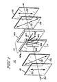
- Figure 1 is a schematic view of a liquid crystal display device in accordance with an embodiment of the present invention.
- Figure 2 is a Poincaré sphere diagram showing an elliptical polarization state.
- Figure 3 is a graph of an elliptical polarization state on an orthogonal coordinate system.
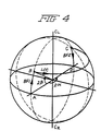
- Figure 4 is a Poincaré sphere diagram showing the state of polarization of light propagating through the LCD device of Figure 1.
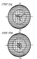
- Figure 5A is a Poincaré sphere diagram showing the percentage of light transmission through an LCD device without birefringent films.
- Figure 5B is a Poincaré sphere diagram showing the percentage of light transmission through an LCD device in accordance with the present invention.
- Figure 6 is a graph of the measured percentage of light transmission in the "off" state versus wavelength for the liquid crystal display device of Figure 1 with birefringent films having different retardations.
- a liquid crystal display (LCD) device 10 includes a liquid crystal cell 12 which comprises two parallel flat transparent plates 14a and 14b, preferably of glass, sealably containing a quantity of nematic liquid crystal material.
- the LC material includes a multiplicity of LC molecules 16 which are divided into groups; the LC molecules in each group are oriented relative to each other to form a twisted structure between plates 14a and 14b.
- the difference between the angle or orientation of first molecule 16a and last molecule 16e is the twist angle of the LC cell.
- Light propagating through LC cell 12 will be a linear combination of the two normal modes of the LC cell.
- the two normal modes are elliptically polarized by LC cell 12 and will have ellipticity ⁇ , which is a function of the light wavelength ( ⁇ ), the birefringence ( ⁇ n) of the cell and the pitch (p) of the LC molecules in the twisted nematic structure between entrance plate 14a and exit plate 14b.
- LC display 10 operates like a camera shutter to control the quantity of light passing through device 10.
- LC cell 12 may be energized to an "on” state to allow light transmission or not energized and in an “off” state; ideally, the LC cell in the "off” state should completely block out any light transmission and look black for the display to exhibit the desired contrast, but some light at different wavelengths may leak through the LC cell.
- a front or entrance polarizer 18 is disposed substantially parallel to entrance plate 14a and a rear or exit polarizer 20 is disposed substantially parallel to exit plate 14b.
- Entrance polarizer 18 has a polarization or transmission direction (indicated by arrows 22) that preferably corresponds to the orientation direction of first LC molecule 16a and exit polarizer 20 has a transmission direction (indicated by arrows 24) that is preferably orthogonal to last LC molecule 16e to minimize the amount of light transmission through device 10 in the "off" state.
- Device 10 would work as well if the entrance and exit polarizers were rotated 90° and thereby coupled to the other of the two normal modes of LC cell 12.
- a first birefringent film (BF) 26 is disposed between entrance polarizer 18 and LC cell entrance plate 14a and substantially parallel to both; a second birefringent film 28 is also disposed between exit plate 14b and exit polarizer 20 and substantially parallel to each.
- First birefringent film 26 has a selected birefringence ( ⁇ n' 1 ) and a fast axis (shown by arrows 30) oriented in a selected direction to transform linear polarized light from entrance polarizer 18 into elliptically polarized light with ellipticity ⁇ and azimuth ⁇ which both correspond to one of the two normal modes of LC cell 12.
- Second birefringent film 28 has a selected birefringence ( ⁇ n' 2 ) and a fast axis (arrows 32) oriented in a selected direction to cause elliptically polarized light exiting LC cell 12 to be transformed into linearly polarized light that is orthogonal to the transmission direction 24 of exit polarizer 20; therefore, exit polarizer 20 will absorb the light and the output of device 10 will appear black when LC cell 12 is in an unexcited "off" state.
- Fast axis 30 of first birefringent film 26 is preferably oriented at an angle of about 45° relative to both the entrance polarizer direction (arrows 22) and the orientation direction of first LC molecule 16a
- fast axis 32 of second birefringent film 28 is preferably oriented at an angle of about 45° relative to both the exit polarizer direction (arrows 24) and the orientation direction of last LC molecule 16e.
- orientation directions also permit the birefringence of both birefringent films 26 and 28 to be substantially equal.
- the polarization directions in Figure 1 are merely for purposes of illustration and other directions can be used as well provided the relative polarization directions of the different constituents are maintained substantially as described above for optimum performance.
- any polarization state of propagating light can be represented by a point on the surface of a Poincaré sphere diagram ( Figure 2).
- the equator of the sphere is the locus of all linearly polarized states and the poles, C L and C R , respectively, represent the left- and right-handed circular polarized states. All other points on the Poincaré sphere surface represent elliptical polarization states.
- an elliptical polarization state may be represented on an X-Y orthogonal coordinate system ( Figure 3) as some azimuth ⁇ and ellipticity ⁇ .
- This same elliptical polarization state would be represented by the point P (2 ⁇ , 2 ⁇ ) on the Poincaré sphere diagram ( Figure 2). All angles are doubled when transferred from an orthogonal coordinate system to the Poincaré sphere and the X-Y axis is rotated from 90° to 180°.
- Linearly polarized light preferably propagates through LCD device 10 in the direction indicated by arrow 34 ( Figure 1). Entrance polarizer 18 will pass that one mode, of the two normal modes of linearly polarized light, which corresponds to the polarization orientation 22 of entrance polarizer 18, and will block the other normal mode.
- the linear polarization state at the output of entrance polarizer 18 may be represented by point A on the Poincaré sphere ( Figure 4).
- Second birefringent film 28 will convert the elliptically polarized light to a linearly polarized state at point D because second birefringent film 28 has selected birefringence ( ⁇ n' 2 ) and selected fast axis 32 orientation to rotate the polarization state back to the equator of the Poincaré sphere at point D (2 ⁇ , 0).
- the linear polarized light at point D will have a polarization direction equal to the orientation direction of last LC molecule 16e.
- Exit polarizer 20 will extinguish the linear polarized light and the output of LCD device 10 will be black in the "off" state because exit polarizer 20 is oriented orthogonally to last LC molecule 16e ( Figure 1).
- the elliptical polarization of different colored light propagating through the birefringent films and the LC cell will vary because the ellipticity of light propagating through these constituents is a function of the wavelength of the light.
- the percentage of light transmission for different colored light at the output of exit polarizer 20 may be graphically estimated using Poincaré sphere diagrams ( Figures 5A and 5B) and looking back into exit polarizer 20. Constant transmission contours for 0.1%, 1% and 10% light transmission are superimposed on Figures 5A and 5B.
- With the birefringent films leakage of the red and blue light can be limited to less than about 0.5% (Figure 5B).
- Figure 6 shows percentage light transmission versus wavelength for a 90° twisted nematic LC cell filled with Merck ZLI-3376® liquid crystal material having a ⁇ n of 0.085 at a wavelength of 590nm and a cell thickness of about 5.9 ⁇ m.
- Graphs are shown for the LC cell without birefringent films (tn) and with birefringent films having retardations of about 25, 32 and 40nm.
- the birefringent films were formed by stretching a polymer sheet over a thin glass substrate and bonding the sheet to the substrate with an ultra-violet curable adhesive to maintain a stable retardation.
- exit polarizer 20 is below about 0.5% over most of the visible light spectrum for the LCD devices with birefringent films 26 and 28 and the output was substantially black for the "off" state. These results are superior to the results obtained with prior art devices which utilized a single birefringent film having retardations of several hundred nanometers.
- the birefringent films with retardations below about 100nm also appear to be relatively insensitive to LC cell thickness, polarizer orientation, birefringent film orientation, viewing angle and different wavelengths.
Landscapes
- Physics & Mathematics (AREA)
- Nonlinear Science (AREA)
- Chemical & Material Sciences (AREA)
- Crystallography & Structural Chemistry (AREA)
- General Physics & Mathematics (AREA)
- Optics & Photonics (AREA)
- Mathematical Physics (AREA)
- Liquid Crystal (AREA)
- Polarising Elements (AREA)
Claims (10)
- Flüssigkristall-Anzeigevorrichtung (10) enthaltend:einen Eingangs-Polarisator (18) mit einer Polarisationsachse (22) zum linearen Polarisieren von in die Vorrichtung eintretendem Licht (34) in einer ersten gewählten Richtung (16a) ;einen ersten doppeltbrechenden Film (26), der benachbart zu und im wesentlichen parallel zu dem Eingangs-Polarisator (18) angeordnet ist, um das linear polarisierte eintretende Licht in elliptisch polarisiertes Licht mit einer gewählten Elliptizität bzw. Abplattung β umzuwandeln:eine nematische Verdrehungs-Flüssigkristallzelle (12), die im wesentlichen parallel zu dem ersten doppelt brechenden Film (26) und benachbart dazu angeordnet und in der Lage ist, das elliptisch polarisierte Licht, das in die Zelle (12) eintritt, von der ersten gewählten Richtung (16a) in eine zweite gewählte Richtung (16e) zu drehen, wenn die Zelle (12) in einem nicht-angeregten "Aus"-Zustand ist, wobei der dem Licht erteilte Drehwinkel dem Verdrehungswinkel der Zelle (12) entspricht;einen zweiten doppeltbrechenden Film (28), der benachbart zu und im wesentlichen parallel zu der Flüssigkristallzelle (12) angeordnet ist, um das elliptisch polarisierte Licht, das aus der Flüssigkristallzelle (12) austritt, in Licht umzuwandeln, das in der zweiten gewählten Richtung (16e) linear polarisiert ist; undeinen Ausgangs-Polarisator (20), der benachbart zu und im wesentlichen parallel zu dem zweiten doppeltbrechenden Film (28) angeordnet ist und eine Polarisationsachse (24) hat, die im wesentlichen orthogonal zu der zweiten gewählten Richtung (16e) angeordnet ist, dadurch gekennzeichnet, daß die Zelle (12) eine Normalmode-Elliptizität bzw. -Abflachung hat, die im wesentlichen gleich der gewählten Elliptizität- bzw. -abflachung β ist, und jeder der Filme eine maximale Verzögerung von 100 Nanometer für alle sichtbaren Wellenlängen hat, wodurch Licht, das aus dem zweiten doppeltbrechenden Film (28) austritt, gelöscht wird, wenn die Flüssigkristallzelle (12) in dem "Aus" -Zustand ist.
- Vorrichtung nach Anspruch 1, wobei die Normalmode-Elliptizität bzw. -Abflachung der Flüssigkristallzelle (12) so gewählt ist, daß eine gewählte Wellenlänge des Lichtes durch den Ausgangs-Polarisator (20) vollständig gesperrt wird.
- Vorrichtung nach Anspruch 1, wobei jeder der ersten und zweiten doppeltbrechenden Filme (26, 28) enthält:ein Glas-Substrat; undein Blatt aus Polymermaterial, das über das Glas-Substrat gespannt und mit dem Substrat verbunden ist durch einen ultraviolett-härtbaren Klebstoff, um eine stabile Verzögerung auszubilden.
- Vorrichtung nach Anspruch 1, wobei jeder der ersten und zweiten doppeltbrechenden Filme (26, 28) eine schnelle Achse (30, 32) hat, wobei jede der schnellen Achsen (30, 32) in der gleichen Richtung orientiert ist.
- Vorrichtung nach Anspruch 4, wobei die schnelle Achse (30) des ersten doppeltbrechenden Films bei etwa 45° relativ zu der Polarisationsachse (22) des Eintritts-Polarisators (18) bzw. der ersten gewählten Richtung (16a) orientiert ist, und die schnelle Achse (32) des zweiten doppeltbrechenden Films bei etwa 45° relativ zu der Polarisationsachse (24) des Ausgangs-Polarisators (20) bzw. der zweiten gewählten Richtung (16e) orientiert ist.
- Vorrichtung nach Anspruch 1, wobei jeder der ersten und zweiten doppeltbrechenden Filme (26, 28) eine Verzögerung von etwa 25 Nanometer hat.
- Vorrichtung nach Anspruch 1, wobei der zweite doppeltbrechende Film (28) eine gewählte Doppelbrechung hat, um Licht mit der gewählten Elliptizität bzw. Abflachung β in linear polarisiertes Licht umzuwandeln.
- Vorrichtung nach Anspruch 1, wobei die Flüssigkristallzelle (12) einen Verdrehungs- bzw. Twistwinkel von etwa 90° hat.
- Vorrichtung nach Anspruch 1, wobei die Flüssigkristallzelle (12) ein super-verdrehtes nematisches Material aufweist.
- Vorrichtung nach Anspruch 1, wobei die Flüssigkristallzelle (12) den Gooch-Tarry-Minimumzustand erfüllt,
damit Licht gewählter Wellenlänge durch den Ausgangs-Polarisator (24) vollständig gesperrt wird.
Applications Claiming Priority (2)
| Application Number | Priority Date | Filing Date | Title |
|---|---|---|---|
| US456915 | 1989-12-26 | ||
| US07/456,915 US5107356A (en) | 1989-12-26 | 1989-12-26 | Liquid crystal display device with birefringent films |
Publications (3)
| Publication Number | Publication Date |
|---|---|
| EP0435526A2 EP0435526A2 (de) | 1991-07-03 |
| EP0435526A3 EP0435526A3 (en) | 1992-04-08 |
| EP0435526B1 true EP0435526B1 (de) | 1996-06-12 |
Family
ID=23814663
Family Applications (1)
| Application Number | Title | Priority Date | Filing Date |
|---|---|---|---|
| EP90313633A Expired - Lifetime EP0435526B1 (de) | 1989-12-26 | 1990-12-14 | Flüssigkristall-Anzeigevorrichtung |
Country Status (6)
| Country | Link |
|---|---|
| US (1) | US5107356A (de) |
| EP (1) | EP0435526B1 (de) |
| JP (1) | JP3217354B2 (de) |
| KR (1) | KR100186777B1 (de) |
| DE (1) | DE69027415T2 (de) |
| SG (1) | SG44506A1 (de) |
Families Citing this family (25)
| Publication number | Priority date | Publication date | Assignee | Title |
|---|---|---|---|---|
| US5243455A (en) * | 1990-05-11 | 1993-09-07 | The University Of Colorado Foundation, Inc. | Chiral smectic liquid crystal polarization interference filters |
| US5231521A (en) * | 1989-10-30 | 1993-07-27 | The University Of Colorado Foundation, Inc. | Chiral smectic liquid crystal polarization interference filters |
| US5184236A (en) * | 1990-08-10 | 1993-02-02 | Casio Computer Co., Ltd. | Twisted nematic liquid crystal display device with retardation plates having phase axis direction within 15° of alignment direction |
| JP3039570B2 (ja) * | 1991-06-24 | 2000-05-08 | キヤノン株式会社 | 投写表示装置 |
| TW200604B (de) * | 1991-09-17 | 1993-02-21 | Philips Nv | |
| US5440413A (en) * | 1991-09-30 | 1995-08-08 | Casio Computer Co., Ltd. | Liquid crystal display device with 2 adjacent biaxial retardation plates having Ny <Nz <Nx |
| DE69329836T2 (de) * | 1992-06-30 | 2001-04-19 | Citizen Watch Co., Ltd. | Flüssigkristall-Anzeigeeinheit und Flüssigkristallprojektor, der diese benutzt |
| JPH06289382A (ja) * | 1993-03-30 | 1994-10-18 | Hitachi Ltd | 液晶表示装置 |
| US5442468A (en) * | 1993-06-21 | 1995-08-15 | Arshach-Applied Science Cars Ltd. | Apparatus for producing color effects |
| US5550661A (en) * | 1993-11-15 | 1996-08-27 | Alliedsignal Inc. | Optical phase retardation film |
| US5499126A (en) | 1993-12-02 | 1996-03-12 | Ois Optical Imaging Systems, Inc. | Liquid crystal display with patterned retardation films |
| US5594568A (en) * | 1993-12-15 | 1997-01-14 | Ois Optical Imaging Systems, Inc. | LCD with a pair of retardation films on one side of normally white liquid crystal layer |
| US5576861A (en) | 1993-12-15 | 1996-11-19 | Ois Optical Imaging Systems, Inc. | Liquid crystal display having a retarder with 100-200nm retardation and having high contrast viewing zone centered in positive or negative vertical region |
| US5570214A (en) * | 1993-12-15 | 1996-10-29 | Ois Optical Imaging Systems, Inc. | Normally white twisted nematic LCD with retardation films on opposite sides of liquid crystal material for improved viewing zone |
| US5907378A (en) * | 1993-12-15 | 1999-05-25 | Ois Optical Imaging Systems, Inc. | Normally white twisted nematic liquid crystal display including retardation films for improving viewing characteristics |
| US5532852A (en) * | 1994-02-23 | 1996-07-02 | Kaiser Aerospace And Electronics Corporation | High speed, high ambient viewability liquid crystal display assembly |
| US5638200A (en) * | 1995-02-03 | 1997-06-10 | Ois Optical Imaging Systems, Inc. | Liquid crystal display with tilted retardation film |
| US5610743A (en) * | 1995-10-30 | 1997-03-11 | United Microelectronics Corporation | Liquid crystal display including concentric shapes and radial spokes which has an improved viewing angle |
| WO1999031987A1 (en) | 1997-12-19 | 1999-07-01 | Taro Pharmaceuticals U.S.A., Inc. | Topical carbamazepine formulations and methods of use |
| JP2000035572A (ja) * | 1998-07-16 | 2000-02-02 | Mitsubishi Electric Corp | 液晶表示装置 |
| JP3293586B2 (ja) * | 1999-03-16 | 2002-06-17 | 日本電気株式会社 | 液晶表示装置及びその製造方法 |
| JP3863446B2 (ja) * | 2002-03-08 | 2006-12-27 | シャープ株式会社 | 液晶表示装置 |
| JP4410055B2 (ja) * | 2004-08-02 | 2010-02-03 | 日東電工株式会社 | 位相差粘着剤層、その製造方法、粘着型光学フィルム、その製造方法および画像表示装置 |
| KR101206723B1 (ko) * | 2010-03-17 | 2012-11-30 | 주식회사 엘지화학 | 원편광판 및 이를 포함하는 반사형 액정표시장치 |
| KR102260453B1 (ko) * | 2014-04-03 | 2021-06-07 | 삼성디스플레이 주식회사 | 윈도우 부재 및 이를 구비하는 표시 장치 |
Family Cites Families (10)
| Publication number | Priority date | Publication date | Assignee | Title |
|---|---|---|---|---|
| US4398805A (en) * | 1981-07-06 | 1983-08-16 | General Electric Company | Transflective liquid crystal display |
| JPS5867369U (ja) * | 1981-10-28 | 1983-05-07 | シャープ株式会社 | 液晶表示装置 |
| FR2564605B1 (fr) * | 1984-05-18 | 1987-12-24 | Commissariat Energie Atomique | Cellule a cristal liquide susceptible de presenter une structure homeotrope, a birefringence compensee pour cette structure |
| GB2171549B (en) * | 1985-02-15 | 1988-05-18 | Citizen Watch Co Ltd | Liquid crystal display device |
| DE3752339T2 (de) * | 1986-05-19 | 2002-05-08 | Seiko Epson Corp., Tokio/Tokyo | Flüssigkristallanzeigevorrichtung |
| EP0297841B1 (de) * | 1987-06-30 | 1993-09-22 | Sumitomo Chemical Company, Limited | Phasenverzögernde Polymerfilme und polarisierende Bauteile |
| EP0350075A3 (de) * | 1988-07-08 | 1990-09-05 | Kabushiki Kaisha Toshiba | Flüssigkristall-Anzeigevorrichtung |
| US5033825A (en) * | 1988-12-26 | 1991-07-23 | Kabushiki Kaisha Toshiba | Ferroelectric liquid crystal display device having equalizing means |
| CA2009319C (en) * | 1989-02-06 | 1994-11-01 | Hiroshi Ohnishi | Liquid crystal display device |
| EP0394519B1 (de) * | 1989-04-26 | 1994-02-02 | Fujimori Kogyo Co., Ltd. | Flüssigkristallanzeigetafel mit optischem Phasenschiebersubstrat |
-
1989
- 1989-12-26 US US07/456,915 patent/US5107356A/en not_active Expired - Lifetime
-
1990
- 1990-11-22 JP JP31569490A patent/JP3217354B2/ja not_active Expired - Lifetime
- 1990-12-14 EP EP90313633A patent/EP0435526B1/de not_active Expired - Lifetime
- 1990-12-14 SG SG1996001145A patent/SG44506A1/en unknown
- 1990-12-14 DE DE69027415T patent/DE69027415T2/de not_active Expired - Lifetime
- 1990-12-26 KR KR1019900021888A patent/KR100186777B1/ko not_active Expired - Lifetime
Also Published As
| Publication number | Publication date |
|---|---|
| SG44506A1 (en) | 1997-12-19 |
| DE69027415T2 (de) | 1997-02-06 |
| JPH03200213A (ja) | 1991-09-02 |
| EP0435526A2 (de) | 1991-07-03 |
| JP3217354B2 (ja) | 2001-10-09 |
| US5107356A (en) | 1992-04-21 |
| KR910012777A (ko) | 1991-08-08 |
| EP0435526A3 (en) | 1992-04-08 |
| KR100186777B1 (ko) | 1999-05-01 |
| DE69027415D1 (de) | 1996-07-18 |
Similar Documents
| Publication | Publication Date | Title |
|---|---|---|
| US5107356A (en) | Liquid crystal display device with birefringent films | |
| EP0816906B1 (de) | Flüssigkristallvorrichtungen | |
| KR100239266B1 (ko) | 액정표시장치 및 그의 위상지연 보상방법 | |
| EP1750165B1 (de) | Transflektive Flüssigkristallanzeigen | |
| EP0932072B1 (de) | Flüssigkristallanzeige-Vorrichtung und Verfahren zu deren Herstellung | |
| EP0393191B1 (de) | Flüssigkristallanzeigeanordnung | |
| US5184236A (en) | Twisted nematic liquid crystal display device with retardation plates having phase axis direction within 15° of alignment direction | |
| US6359671B1 (en) | High contrast liquid crystal device | |
| US20040246418A1 (en) | Liquid crystal display | |
| JPH11503247A (ja) | 液晶アクロマティク複合リターダ | |
| US20050275779A1 (en) | Liquid crystal display | |
| JP2000029010A (ja) | 液晶表示装置 | |
| US20050068481A1 (en) | Liquid crystal display device having homeotropic alignment liquid crystal panel | |
| US4859037A (en) | Liquid crystal electrically-controlled birefringence display devices with improved contrast | |
| US7646454B2 (en) | Transflective liquid crystal display device | |
| EP0142326A1 (de) | Flüssigkristallanzeigevorrichtung | |
| JP3070181B2 (ja) | 液晶表示装置 | |
| KR100357359B1 (ko) | 복굴절막을사용한액정표시장치 | |
| EP0727691A1 (de) | Flüssigkristall-Anzeigevorrichtung mit aktiver Matrix und homogen ausgerichtetem, nicht verdrillten Flüssigkristall, sowie Kompensation der Verzögerung | |
| JP3619506B2 (ja) | 液晶表示装置 | |
| US5479281A (en) | Display devices | |
| US20020105488A1 (en) | Active matrix type liquid crystal display | |
| JP3289370B2 (ja) | カラー液晶表示装置 | |
| JP3619507B2 (ja) | 液晶表示装置 | |
| JPH10104617A (ja) | 液晶画像表示装置 |
Legal Events
| Date | Code | Title | Description |
|---|---|---|---|
| PUAI | Public reference made under article 153(3) epc to a published international application that has entered the european phase |
Free format text: ORIGINAL CODE: 0009012 |
|
| AK | Designated contracting states |
Kind code of ref document: A2 Designated state(s): DE FR GB IT |
|
| PUAL | Search report despatched |
Free format text: ORIGINAL CODE: 0009013 |
|
| AK | Designated contracting states |
Kind code of ref document: A3 Designated state(s): DE FR GB IT |
|
| 17P | Request for examination filed |
Effective date: 19920930 |
|
| 17Q | First examination report despatched |
Effective date: 19940418 |
|
| GRAH | Despatch of communication of intention to grant a patent |
Free format text: ORIGINAL CODE: EPIDOS IGRA |
|
| GRAH | Despatch of communication of intention to grant a patent |
Free format text: ORIGINAL CODE: EPIDOS IGRA |
|
| GRAA | (expected) grant |
Free format text: ORIGINAL CODE: 0009210 |
|
| AK | Designated contracting states |
Kind code of ref document: B1 Designated state(s): DE FR GB IT |
|
| ET | Fr: translation filed | ||
| REF | Corresponds to: |
Ref document number: 69027415 Country of ref document: DE Date of ref document: 19960718 |
|
| ITF | It: translation for a ep patent filed | ||
| PLBE | No opposition filed within time limit |
Free format text: ORIGINAL CODE: 0009261 |
|
| STAA | Information on the status of an ep patent application or granted ep patent |
Free format text: STATUS: NO OPPOSITION FILED WITHIN TIME LIMIT |
|
| 26N | No opposition filed | ||
| REG | Reference to a national code |
Ref country code: GB Ref legal event code: IF02 |
|
| REG | Reference to a national code |
Ref country code: FR Ref legal event code: TP |
|
| REG | Reference to a national code |
Ref country code: FR Ref legal event code: D6 |
|
| PGFP | Annual fee paid to national office [announced via postgrant information from national office to epo] |
Ref country code: FR Payment date: 20091228 Year of fee payment: 20 Ref country code: GB Payment date: 20091127 Year of fee payment: 20 Ref country code: IT Payment date: 20091218 Year of fee payment: 20 |
|
| PGFP | Annual fee paid to national office [announced via postgrant information from national office to epo] |
Ref country code: DE Payment date: 20091218 Year of fee payment: 20 |
|
| REG | Reference to a national code |
Ref country code: GB Ref legal event code: PE20 Expiry date: 20101213 |
|
| PG25 | Lapsed in a contracting state [announced via postgrant information from national office to epo] |
Ref country code: GB Free format text: LAPSE BECAUSE OF EXPIRATION OF PROTECTION Effective date: 20101213 |
|
| PG25 | Lapsed in a contracting state [announced via postgrant information from national office to epo] |
Ref country code: DE Free format text: LAPSE BECAUSE OF EXPIRATION OF PROTECTION Effective date: 20101214 |