EP0436098A2 - Procédé de dégazage de l'eau purifiÀ©e par osmose inverse et installation d'osmose inverse pour la mise en oeuvre du procédé - Google Patents
Procédé de dégazage de l'eau purifiÀ©e par osmose inverse et installation d'osmose inverse pour la mise en oeuvre du procédé Download PDFInfo
- Publication number
- EP0436098A2 EP0436098A2 EP90121953A EP90121953A EP0436098A2 EP 0436098 A2 EP0436098 A2 EP 0436098A2 EP 90121953 A EP90121953 A EP 90121953A EP 90121953 A EP90121953 A EP 90121953A EP 0436098 A2 EP0436098 A2 EP 0436098A2
- Authority
- EP
- European Patent Office
- Prior art keywords
- reverse osmosis
- line
- pure water
- valve
- water
- Prior art date
- Legal status (The legal status is an assumption and is not a legal conclusion. Google has not performed a legal analysis and makes no representation as to the accuracy of the status listed.)
- Withdrawn
Links
- XLYOFNOQVPJJNP-UHFFFAOYSA-N water Chemical compound O XLYOFNOQVPJJNP-UHFFFAOYSA-N 0.000 title claims abstract description 135
- 238000001223 reverse osmosis Methods 0.000 title claims abstract description 75
- 238000007872 degassing Methods 0.000 title claims abstract description 25
- 238000000034 method Methods 0.000 title claims description 15
- 239000008213 purified water Substances 0.000 title 1
- 238000010438 heat treatment Methods 0.000 claims abstract description 22
- 239000012465 retentate Substances 0.000 claims abstract description 13
- 238000004519 manufacturing process Methods 0.000 claims abstract description 4
- 230000001105 regulatory effect Effects 0.000 claims description 26
- 239000000645 desinfectant Substances 0.000 claims description 17
- 239000012466 permeate Substances 0.000 claims description 13
- 239000007789 gas Substances 0.000 claims description 8
- 239000012141 concentrate Substances 0.000 claims description 6
- 238000011144 upstream manufacturing Methods 0.000 claims description 3
- 238000009434 installation Methods 0.000 claims 2
- 238000000502 dialysis Methods 0.000 abstract description 18
- 238000001631 haemodialysis Methods 0.000 description 11
- 230000000322 hemodialysis Effects 0.000 description 11
- 239000012528 membrane Substances 0.000 description 8
- 238000004659 sterilization and disinfection Methods 0.000 description 7
- 239000000243 solution Substances 0.000 description 5
- 239000002904 solvent Substances 0.000 description 4
- 239000000385 dialysis solution Substances 0.000 description 3
- 239000007788 liquid Substances 0.000 description 3
- 238000002156 mixing Methods 0.000 description 3
- 238000000108 ultra-filtration Methods 0.000 description 3
- 244000052616 bacterial pathogen Species 0.000 description 2
- 238000006243 chemical reaction Methods 0.000 description 2
- 238000005265 energy consumption Methods 0.000 description 2
- 238000001914 filtration Methods 0.000 description 2
- 230000002706 hydrostatic effect Effects 0.000 description 2
- 239000000203 mixture Substances 0.000 description 2
- 238000012856 packing Methods 0.000 description 2
- 239000002245 particle Substances 0.000 description 2
- 239000000523 sample Substances 0.000 description 2
- 239000000126 substance Substances 0.000 description 2
- 239000008399 tap water Substances 0.000 description 2
- 235000020679 tap water Nutrition 0.000 description 2
- 229910021642 ultra pure water Inorganic materials 0.000 description 2
- 239000012498 ultrapure water Substances 0.000 description 2
- 238000002604 ultrasonography Methods 0.000 description 2
- OYPRJOBELJOOCE-UHFFFAOYSA-N Calcium Chemical compound [Ca] OYPRJOBELJOOCE-UHFFFAOYSA-N 0.000 description 1
- DGAQECJNVWCQMB-PUAWFVPOSA-M Ilexoside XXIX Chemical compound C[C@@H]1CC[C@@]2(CC[C@@]3(C(=CC[C@H]4[C@]3(CC[C@@H]5[C@@]4(CC[C@@H](C5(C)C)OS(=O)(=O)[O-])C)C)[C@@H]2[C@]1(C)O)C)C(=O)O[C@H]6[C@@H]([C@H]([C@@H]([C@H](O6)CO)O)O)O.[Na+] DGAQECJNVWCQMB-PUAWFVPOSA-M 0.000 description 1
- FYYHWMGAXLPEAU-UHFFFAOYSA-N Magnesium Chemical compound [Mg] FYYHWMGAXLPEAU-UHFFFAOYSA-N 0.000 description 1
- ZLMJMSJWJFRBEC-UHFFFAOYSA-N Potassium Chemical compound [K] ZLMJMSJWJFRBEC-UHFFFAOYSA-N 0.000 description 1
- 230000001580 bacterial effect Effects 0.000 description 1
- 239000011575 calcium Substances 0.000 description 1
- 229910052791 calcium Inorganic materials 0.000 description 1
- 230000001276 controlling effect Effects 0.000 description 1
- 230000008878 coupling Effects 0.000 description 1
- 238000010168 coupling process Methods 0.000 description 1
- 238000005859 coupling reaction Methods 0.000 description 1
- 238000002425 crystallisation Methods 0.000 description 1
- 230000008025 crystallization Effects 0.000 description 1
- 230000007423 decrease Effects 0.000 description 1
- 230000001419 dependent effect Effects 0.000 description 1
- 238000001514 detection method Methods 0.000 description 1
- 238000004821 distillation Methods 0.000 description 1
- 230000000694 effects Effects 0.000 description 1
- 239000000706 filtrate Substances 0.000 description 1
- 239000012535 impurity Substances 0.000 description 1
- 238000012432 intermediate storage Methods 0.000 description 1
- 150000002500 ions Chemical class 0.000 description 1
- 239000011777 magnesium Substances 0.000 description 1
- 229910052749 magnesium Inorganic materials 0.000 description 1
- 230000007257 malfunction Effects 0.000 description 1
- 238000007726 management method Methods 0.000 description 1
- 239000000463 material Substances 0.000 description 1
- 238000005259 measurement Methods 0.000 description 1
- 230000003204 osmotic effect Effects 0.000 description 1
- 238000002616 plasmapheresis Methods 0.000 description 1
- 229920003023 plastic Polymers 0.000 description 1
- 239000004033 plastic Substances 0.000 description 1
- 239000011591 potassium Substances 0.000 description 1
- 229910052700 potassium Inorganic materials 0.000 description 1
- 238000011085 pressure filtration Methods 0.000 description 1
- 230000002265 prevention Effects 0.000 description 1
- 239000002510 pyrogen Substances 0.000 description 1
- 239000011734 sodium Substances 0.000 description 1
- 229910052708 sodium Inorganic materials 0.000 description 1
- 229910001220 stainless steel Inorganic materials 0.000 description 1
- 239000010935 stainless steel Substances 0.000 description 1
- 239000000758 substrate Substances 0.000 description 1
- 229960005486 vaccine Drugs 0.000 description 1
- 238000009849 vacuum degassing Methods 0.000 description 1
- 238000013022 venting Methods 0.000 description 1
Images
Classifications
-
- B—PERFORMING OPERATIONS; TRANSPORTING
- B01—PHYSICAL OR CHEMICAL PROCESSES OR APPARATUS IN GENERAL
- B01D—SEPARATION
- B01D61/00—Processes of separation using semi-permeable membranes, e.g. dialysis, osmosis or ultrafiltration; Apparatus, accessories or auxiliary operations specially adapted therefor
- B01D61/02—Reverse osmosis; Hyperfiltration ; Nanofiltration
- B01D61/025—Reverse osmosis; Hyperfiltration
-
- B—PERFORMING OPERATIONS; TRANSPORTING
- B01—PHYSICAL OR CHEMICAL PROCESSES OR APPARATUS IN GENERAL
- B01D—SEPARATION
- B01D19/00—Degasification of liquids
- B01D19/0068—General arrangements, e.g. flowsheets
-
- C—CHEMISTRY; METALLURGY
- C02—TREATMENT OF WATER, WASTE WATER, SEWAGE, OR SLUDGE
- C02F—TREATMENT OF WATER, WASTE WATER, SEWAGE, OR SLUDGE
- C02F1/00—Treatment of water, waste water, or sewage
- C02F1/20—Treatment of water, waste water, or sewage by degassing, i.e. liberation of dissolved gases
-
- C—CHEMISTRY; METALLURGY
- C02—TREATMENT OF WATER, WASTE WATER, SEWAGE, OR SLUDGE
- C02F—TREATMENT OF WATER, WASTE WATER, SEWAGE, OR SLUDGE
- C02F1/00—Treatment of water, waste water, or sewage
- C02F1/44—Treatment of water, waste water, or sewage by dialysis, osmosis or reverse osmosis
- C02F1/441—Treatment of water, waste water, or sewage by dialysis, osmosis or reverse osmosis by reverse osmosis
Definitions
- the invention relates to a method for degassing pure water obtained in reverse osmosis and a reverse osmosis system for the production of pure water, in particular pure water for medical purposes with a flow tank, a reverse osmosis module, a high pressure pump in the connecting line between the flow tank and the reverse osmosis module, a concentrate line connects the reverse osmosis module to the flow tank and with a permeate line and a return line branching off from it to the flow tank.
- Hyperfiltration or reverse osmosis like ultrafiltration, is a pressure filtration process.
- the real difference between hyperfiltration and ultrafiltration is the size of the particles separated by the process.
- Reverse osmosis generally removes particles or molecules from a solvent that have a relatively low molecular weight.
- a good treatment of the dialysis water is particularly necessary for clinical hemodialysis. Too high or fluctuating concentrations of calcium, magnesium, potassium and sodium or too high bacterial counts and pyrogen levels can cause side effects during treatment. Reverse osmosis has therefore become significantly more important in the treatment of dialysis water in recent years.
- the reverse osmosis systems are operated continuously. If possible, there is no intermediate storage of ultrapure water on the permeate side, i.e. the water flowing to the dialysis machines comes directly from the reverse osmosis system.
- the fittings, sensors, circuit lines etc. are designed in such a way that there are no flow dead spaces in the system in which germs can occur. Therefore only plastics and stainless steel are used as materials.
- the systems are also disinfected regularly.
- a reverse osmosis system which can be connected to a hemodialysis device as a separate device.
- This reverse osmosis system has a reverse osmosis module and a flow tank which is connected to the water supply via a conductivity probe and a solenoid valve.
- the raw water in the flow tank is fed to the reverse osmosis module via a pump, where a membrane is arranged, through which the water arriving at high pressure passes as filtrate and is fed to the dialysis machine via an outlet line, which is equipped with a permeate solenoid valve and another conductivity probe .
- the permeate line is connected to the flow tank via a return line.
- the retentate, which flows out of the reverse osmosis module is in turn fed to the flow tank or the outflow.
- the flow tank is also equipped with a vaccine connection for the supply of disinfectant.
- Degassed water must be used, in particular, for hemodialysis, since the dialysis fluid in the dialyzer is usually pressurized. to achieve ultrafiltration. Non-degassed water will degas and fill the dialyzer with air, which reduces the effectiveness of the dialysis.
- DE-PS 28 58 204 From DE-PS 28 58 204 it is known to suck the water in a separate supply unit upstream of the dialysis device for the purpose of degassing with the aid of a pump, the degassing pump, through a throttle and a container connected behind it. In the vacuum area, gas is released in small bubbles, pumped through the pump and separated on the pressure side.
- the degassing process now takes a while when water is subjected to a vacuum.
- either the dwell time in the negative pressure area can be increased, which can be done, for example, through repeated recirculation of the water or the dialysis fluid, or you can introduce germs according to the type of crystallization nuclei or impurities in the water that lead to a faster Lead gas release.
- these packing elements have the disadvantage that they are also a good substrate for germ growth.
- the object of the present invention is therefore a method and a reverse osmosis system with which these disadvantages are to be avoided, the effectiveness and the degassing quality of the pure water in particular being improved and components being saved.
- the degassing quality of the pure water can be significantly improved with the saving of components if the pure water is pumped out of the element chamber of the reversing module by means of a vacuum pump in such a way that a vacuum is maintained in the permeate chamber, and that the pressure released in the process Gases in an air separator downstream of the vacuum pump are removed.
- the reverse osmosis system is characterized in that a degassing device is arranged in the permeate chamber at the outlet of the pure water compartment of the reverse osmosis module.
- the advantage of the arrangement is that the reverse osmosis membrane can be used for degassing at the same time.
- the reverse osmosis membrane has a large surface area which, when placed under negative pressure, also represents a reaction surface for the gas release. So if the reverse osmosis membrane is used directly as a throttle, there is a large reaction area at the same time present, which leads to an effective gas release. An additional throttle device is therefore unnecessary.
- the degassing device has a vacuum pump and an air separator.
- the vacuum pump is connected to the pure water compartment of the reverse osmosis module.
- the pure water is thus pumped out by this vacuum pump, the pump being regulated so that a vacuum of approx. 600 mm Hg results. This results in a degassing of the pure water.
- the air separator downstream of the vacuum pump which can be designed as a cyclone, the gas bubbles are separated from the water and enter a recirculation line connected to the air separator.
- the pure water then flows through a line to the consumer, e.g.
- a heating device is provided between the supply tank and the reverse osmosis module.
- the heating device can be preceded by a heat exchanger unit, the primary circuit of the heat exchanger being arranged between the flow tank and the heating device.
- the secondary circuit of the heat exchanger is located in the return line coming from the reverse osmosis module, in which the heated retentate is either returned to the flow tank or to the outlet.
- a connecting line can be connected to this retentate line before the secondary circuit of the heat exchanger, through which the used pure water, which is also heated, flows back from the pure water consumer.
- the heating device consists of a heating chamber, to which the preheated liquid is fed.
- the liquid is brought to a predetermined temperature, preferably between 20 and 34 degrees C, and kept at this temperature by a temperature sensor and a control unit connected to it.
- the heated raw water flows via a connecting line from this heating device to a conductivity measuring cell, with which the conductivity of the raw water is measured for the purpose of assessing the functionality of the reverse osmosis module and from there via a further line section to the reverse osmosis module.
- a high-pressure pump is arranged in front of the reverse osmosis module in order to generate the required excess pressure in the reverse osmosis module.
- This high-pressure pump is preferably coupled to a further expansion pump arranged in the return line (retentate line) coming from the reverse osmosis module.
- the delivery volume of the expansion pump is preferably up to approximately 70% (50-70%) of the delivery volume of the high-pressure pump. This creates an overpressure on the raw water side, which leads to the filtration of the quantity of water determined by the difference in delivery volume through the membrane. Due to the relaxation of the retentate, the relaxation pump is driven, which due to the coupling with the high pressure pump also drives it. In this way, the energy consumption of the entire reverse osmosis system is significantly reduced compared to the known systems according to the prior art.
- the invention provides several options for simplifying the disinfection of the entire system, including the pure water consumer. If a hemodialysis machine is connected as a pure water consumer, this usually has a disinfectant suction device. In this case, the dialysis machine is switched to disinfection mode. The disinfectant mixture flowing off the dialysis machine is not conveyed to the outlet according to the invention, but is diverted through a recirculation valve to the flow tank, from where it returns to the osmosis circuit and then back to the dialysis device. In this way, both the reverse osmosis system and the connected hemodialysis machine are disinfected.
- a disinfectant supply line is additionally connected to the return line coming from the pure water consumer, which leads into the heat exchanger.
- the disinfectant or disinfectant concentrate is therefore not fed into the dialysis device but into the reverse osmosis system.
- the reverse osmosis system is designed for hot disinfection.
- the heating device is set to approx. 90 degrees and the recirculation valve located in the secondary circuit of the heat exchanger and the flow tank is set to recirculation.
- a regulating and control unit (second regulating and control unit) is provided, which is connected, inter alia, to the recirculation valve, the heating device and the conductivity measuring device in the raw water line.
- a control and regulating unit (first control and regulating unit) is provided for the area of the flow container.
- This first regulating and control unit is connected to the recirculation valve, a level meter arranged in the feed tank and the second regulating and control unit as well as a water inlet valve in the feed line of the feed tank. If the inflow into the flow tank is greater than the outlet, the level in the level measuring chamber of the flow tank increases, which is continuously monitored by a level sensor, which can be an ultrasonic sensor. With the help of the control and regulating unit, it is possible to control the quality of the raw water that is fed to the reverse osmosis module will stop.
- the mixing ratio is controlled by controlling the water inlet valve and the recirculation valve, the measured values obtained from the conductivity measuring cell arranged in the raw water line and being supplied to the regulating and control units being taken into account accordingly. If the water level in the flow tank drops as detected by the level meter, the first control unit opens the water inlet valve accordingly. In this way, the quality of the raw water supplied to the reverse osmosis module can be optimally adjusted, so that the yield of pure water can be increased. The influence of tap water quality on permeate quality can thus be controlled.
- the quality of the pure water is significantly increased by the degassing device provided according to the invention and by the heating device, while the yield of the reverse osmosis system can be increased and kept constant.
- the reverse osmosis system according to the invention is therefore particularly to be used as an integrated component of a dialysis device.
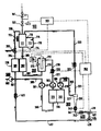
- the reverse osmosis system is shown schematically in the figure.
- the entire system consists of a total of five modules, which are identified by the reference numerals 100, 200, 300, 400 and 500 are.
- 100 denotes the unit for regulating the raw water inflow.
- 200 denotes the unit for heating the raw water.
- the reverse osmosis unit and the degassing unit are designated by 300 and the assembly is identified by 400 with the pure water inlet valve 410, from where a line leads to the pure water consumer, not shown.
- 500 indicates the optional device for the supply of disinfectant.
- This pressure is preferably between 1 and 3 bar.
- the flow tank 110 has a level measurement chamber 113 adjacent to the chamber 111, in which the liquid level is continuously monitored by an ultrasound level sensor 114. If this level has risen to a predetermined level above the reference mark 115, the water inlet valve 102 is closed by the measuring and control unit 103, which is connected, among other things, to the ultrasonic level sensor 114.
- the reference mark 115 is used for auto-calibration of the ultrasound level sensor, which works in a known manner as a transit time sensor. It receives two reflection signals as soon as the water level is above the Reference mark lies. The occurrence of two reflections can already be used for level detection.
- the height of the water level in the chamber 113 can be calculated from the ratio of the running time and the known level of the reference mark and the switching signal for the water inlet valve 102 or the recirculation valve 203 can be derived from this information.
- the level can be regulated, for example, in such a way that the chamber 113 is completely filled during the disinfection, which will be described in more detail below.
- other level sensors such as a float switch, can also be used for this function.
- the water inlet chamber 111 also has an emergency outlet 112.
- the outlet of the chamber 111 of the flow container 110 is connected via a hose piece 205 to the primary circuit 202 of the heat exchanger 230, from where the raw water is supplied to the heating device 210 via the line 207.
- the secondary circuit 201 of the heat exchanger 230 is connected both to the retentate line 360 and to the return line 402 of the pure water consumer.
- the raw water is preheated by the heated retentate of the reverse osmosis unit 300 flowing in countercurrent through the secondary circuit 201 and possibly by the used dialysis fluid flowing in from the return line 402.
- the preheated raw water is heated to a predetermined temperature, preferably between 20 and 34 degrees C, by the heating element 212, which is controlled by the temperature sensor 213 and the control unit 214 connected to it brought and kept at this temperature.
- the heated raw water then flows via the connecting line 219 to the conductivity measuring cell 220, where the conductivity of the raw water is measured in order to assess the functionality of the reverse osmosis unit and to control the valves 102 and 203. and from there via the line section 221 to the reverse osmosis unit 300.
- the conductivity measuring cell 220 is connected to the second regulating and control unit 350.
- the reverse osmosis unit 300 has i.a. the pumps 302 and 301 which are energetically coupled to one another, the reverse osmosis module 310 with the two compartments 311 for the raw water and 312 for the pure water, and the degassing device 306 connected to the pure water line 319.
- the pumps 302, 301 energetically coupled to one another pump the raw water through the raw water compartment 311 of the reverse osmosis module 310.
- the pumps 301, 302 operate essentially volumetrically, the delivery volume per unit time of the pump 301 being less than that of the pump 302.
- the delivery volume of the pump 301 is typically fifty to seventy percent of the delivery volume of the pump 302. This creates an overpressure on the raw water side, which leads to the filtration of the amount of water determined by the delivery volume difference through the membrane.
- the pure water is pumped out by the pump 320, which is located in the line 319, 321.
- the pump 320 is controlled so that there is a negative pressure of approximately 600 mm Hg. So there is one Degassing the raw water.
- the gas bubbles are separated from the water.
- the pure water flows via line 341 to the pure water consumer, which in the present case can be a hemodialysis machine. Air and excess pure water are conveyed back to the flow tank 110 via the recirculation line 331, 333. The air in the recycled permeate, which arises from the degassing, escapes in the water inlet chamber 111 and exits the system through the emergency outlet 112.
- a check valve 332 is also arranged in the recirculation line 331, 333 in order to prevent raw water from getting into the pure water line.
- a conductivity measuring cell 340 is connected, which is connected to the control and regulating unit 350, a check valve 342 and the water inlet valve 410, which leads via line 401 to the pure water consumer.
- the water inlet valve 410 is also electrically connected to the control and regulating unit.
- the difference in the delivery rate of the pumps 301 and 302 or the delivery rate of the pump 320 must be at least on average greater than the demand of the connected clean water consumers. Should this demand be subject to short-term fluctuations, the air separator 310 can be dimensioned such that fluctuations in demand are compensated for without air entering the line 341.
- the retentate line 360 in which the pump 301 is arranged, leads via line line 305 to line 402, which the return line from Represents pure water consumers.
- a common line then leads into the secondary circuit 201 of the heat exchanger 230 and from there via the line 204 to a recirculation valve 203, which is a three-way valve, an outlet leading to the outlet.
- the third branch leads via line 206 to the water inlet chamber 111.
- the entire system can be disinfected by switching the recirculation valve 203 to the recirculation position, that is to say the connection of the tube pieces 204 and 206 is established.
- the dialysis machine is switched to the disinfection mode and the disinfectant mixture flowing in the return line 402 then passes through the valve 203 into the flow container 110 and from there again into the reverse osmosis - as well as the dialysis circuit.
- disinfectant or disinfectant concentrate can be fed into the line 402 via a pump 501 arranged in the feed line 502.
- the feed can only get into the reverse osmosis circuit if the recirculation valve 203 is switched so that the disinfectant is led into the flow container 110.
- valve 203 is also switched to the recirculation position, the setpoint of the heating device 210 is set to approximately 90 degrees C.
- control unit 350 which can be controlled by the hemodialysis machine via a connection (not shown in more detail) or, alternatively, can transmit signals to the connected hemodialysis machine, such as a signal, for example, in order to switch to the disinfection mode.
- the regulating and control unit 350 is electrically connected to the conductivity measuring cells 220 and 340 in order to appropriately monitor the quality of the raw water and the pure water.
- Valve 410 is a three-way valve, the third connection of which leads via line 404 to three-way valve 420 in line 404.
- the three-way valve 420 is also connected to the regulating and control unit 350. If a malfunction now occurs, the reverse osmosis system is short-circuited via the connecting line 404. The reverse osmosis system can thus continue to be operated without permeate flowing to the consumer. After eliminating the cause of the error or at the start of operation, a reverse osmosis system takes a long time before the permeate conductivity has reached the setpoint. The two valves 410 and 420 then switch back to operation.
- the electrical connections are shown in dashed lines. There are further connections to the temperature control unit 214 and to the recirculation valve 203 and to the first regulating and control unit 103 is also connected to the recirculation valve 203 and additionally to the water inlet valve 102 in the raw water connection and the level sensor 114.
Landscapes
- Chemical & Material Sciences (AREA)
- Engineering & Computer Science (AREA)
- Water Supply & Treatment (AREA)
- Life Sciences & Earth Sciences (AREA)
- Hydrology & Water Resources (AREA)
- Environmental & Geological Engineering (AREA)
- Organic Chemistry (AREA)
- Chemical Kinetics & Catalysis (AREA)
- Nanotechnology (AREA)
- External Artificial Organs (AREA)
- Separation Using Semi-Permeable Membranes (AREA)
- Physical Water Treatments (AREA)
Applications Claiming Priority (2)
| Application Number | Priority Date | Filing Date | Title |
|---|---|---|---|
| DE3941131 | 1989-12-13 | ||
| DE19893941131 DE3941131C1 (fr) | 1989-12-13 | 1989-12-13 |
Publications (2)
| Publication Number | Publication Date |
|---|---|
| EP0436098A2 true EP0436098A2 (fr) | 1991-07-10 |
| EP0436098A3 EP0436098A3 (en) | 1992-03-04 |
Family
ID=6395368
Family Applications (1)
| Application Number | Title | Priority Date | Filing Date |
|---|---|---|---|
| EP19900121953 Withdrawn EP0436098A3 (en) | 1989-12-13 | 1990-11-16 | Process for degassing purified water obtained by reverse osmosis and reverse osmosis system for carrying out said method |
Country Status (3)
| Country | Link |
|---|---|
| EP (1) | EP0436098A3 (fr) |
| JP (1) | JPH0427485A (fr) |
| DE (1) | DE3941131C1 (fr) |
Cited By (9)
| Publication number | Priority date | Publication date | Assignee | Title |
|---|---|---|---|---|
| EP0535607A3 (en) * | 1991-09-30 | 1993-05-05 | Millipore Corporation | System for purifying and degasifying water by reverse osmosis |
| EP0576752A1 (fr) * | 1991-06-10 | 1994-01-05 | Verity C. Smith | Système de purification d'eau |
| EP0599281A3 (en) * | 1992-11-27 | 1994-06-15 | Wat Wasser Und Umwelttechnik G | Process and apparatus for treating liquids by reverse osmosis. |
| ES2100817A1 (es) * | 1995-06-08 | 1997-06-16 | Batlles Paniagua Jose | Procedimiento para mejorar el rendimiento de la osmosis inversa, aplicado a la desalinizacion de aguas salobres. |
| DE4331102C2 (de) * | 1993-09-14 | 2003-04-17 | Dwa Dialyse Wasser Aufbereitun | Umkehrosmoseanlage und Verfahren zur Regelung einer Umkehrosmoseanlage |
| WO2007045221A1 (fr) | 2005-10-19 | 2007-04-26 | Franz Ferdinand Becker | Appareillage servant a produire des solutions de rinçage aqueuses physiologiques, therapeutiques et chimiotherapeutiques |
| EP1785151A1 (fr) * | 2005-11-09 | 2007-05-16 | Mar Cor Purification, Inc. | Désinfection thermique pour systèmes d'osmose inverse |
| CN102794108A (zh) * | 2011-05-27 | 2012-11-28 | 曼弗雷德·弗尔克尔 | 反渗透系统 |
| US20180169589A1 (en) * | 2015-06-15 | 2018-06-21 | Dmac Ip Pty Ltd | Water treatment system and method |
Families Citing this family (7)
| Publication number | Priority date | Publication date | Assignee | Title |
|---|---|---|---|---|
| DE10113278A1 (de) * | 2001-03-16 | 2002-09-19 | Zahnradfabrik Friedrichshafen | Verfahren zur Aufbereitung von Waschwässern aus der Druckgussimprägnierung und Vorrichtung zur Durchführung des Verfahrens |
| DE102006026107B3 (de) * | 2006-06-03 | 2007-12-13 | Völker, Manfred | Vorrichtung zur Desinfektion einer Umkehrosmoseanlage |
| US9375524B2 (en) | 2011-06-03 | 2016-06-28 | Fresenius Medical Care Holdings, Inc. | Method and arrangement for venting gases from a container having a powdered concentrate for use in hemodialysis |
| ES2536239T3 (es) * | 2012-07-26 | 2015-05-21 | Manfred Völker | Instalación RO y procedimiento para la desinfección de conductos de la instalación RO |
| DE102015217281A1 (de) | 2015-09-10 | 2017-03-16 | Fresenius Medical Care Deutschland Gmbh | Wasseraufbereitungssystem für Dialysebehandlungen |
| EP4124378A1 (fr) * | 2021-07-28 | 2023-02-01 | Greentec Dialysis GmbH | Dispositif de purification d'eau pour dialyse |
| JP7806183B1 (ja) * | 2024-11-15 | 2026-01-26 | 野村マイクロ・サイエンス株式会社 | 温度制御システム、温度制御方法、医薬用水製造装置の殺菌方法及び二次純水製造方法 |
Family Cites Families (4)
| Publication number | Priority date | Publication date | Assignee | Title |
|---|---|---|---|---|
| US4325715A (en) * | 1976-03-24 | 1982-04-20 | Bowman Donald B | Apparatus for degassing hemodialysis liquid |
| GB2078133B (en) * | 1980-06-20 | 1983-09-21 | Vaponics | Reverse osmosis unit-degasifier system |
| DE3243817C2 (de) * | 1982-11-26 | 1986-01-02 | Hager & Elsässer GmbH, 7000 Stuttgart | Verfahren zur Erzeugung von keimarmem Reinwasser |
| FR2591898B1 (fr) * | 1985-12-24 | 1990-08-24 | France Materiel Medical | Procede et dispositif pour le degazage et le chauffage simultanes de l'eau utilisee pour preparer un liquide de dialyse |
-
1989
- 1989-12-13 DE DE19893941131 patent/DE3941131C1/de not_active Expired - Lifetime
-
1990
- 1990-11-16 EP EP19900121953 patent/EP0436098A3/de not_active Withdrawn
- 1990-12-13 JP JP41016090A patent/JPH0427485A/ja active Pending
Cited By (11)
| Publication number | Priority date | Publication date | Assignee | Title |
|---|---|---|---|---|
| EP0576752A1 (fr) * | 1991-06-10 | 1994-01-05 | Verity C. Smith | Système de purification d'eau |
| EP0535607A3 (en) * | 1991-09-30 | 1993-05-05 | Millipore Corporation | System for purifying and degasifying water by reverse osmosis |
| EP0599281A3 (en) * | 1992-11-27 | 1994-06-15 | Wat Wasser Und Umwelttechnik G | Process and apparatus for treating liquids by reverse osmosis. |
| DE4331102C2 (de) * | 1993-09-14 | 2003-04-17 | Dwa Dialyse Wasser Aufbereitun | Umkehrosmoseanlage und Verfahren zur Regelung einer Umkehrosmoseanlage |
| ES2100817A1 (es) * | 1995-06-08 | 1997-06-16 | Batlles Paniagua Jose | Procedimiento para mejorar el rendimiento de la osmosis inversa, aplicado a la desalinizacion de aguas salobres. |
| WO2007045221A1 (fr) | 2005-10-19 | 2007-04-26 | Franz Ferdinand Becker | Appareillage servant a produire des solutions de rinçage aqueuses physiologiques, therapeutiques et chimiotherapeutiques |
| EP1940744B1 (fr) * | 2005-10-19 | 2015-04-15 | Franz Ferdinand Becker | Appareillage servant a produire des solutions de rinçage aqueuses physiologiques, therapeutiques et chimiotherapeutiques |
| EP1785151A1 (fr) * | 2005-11-09 | 2007-05-16 | Mar Cor Purification, Inc. | Désinfection thermique pour systèmes d'osmose inverse |
| CN102794108A (zh) * | 2011-05-27 | 2012-11-28 | 曼弗雷德·弗尔克尔 | 反渗透系统 |
| CN102794108B (zh) * | 2011-05-27 | 2016-07-06 | 曼弗雷德·弗尔克尔 | 反渗透系统 |
| US20180169589A1 (en) * | 2015-06-15 | 2018-06-21 | Dmac Ip Pty Ltd | Water treatment system and method |
Also Published As
| Publication number | Publication date |
|---|---|
| DE3941131C1 (fr) | 1991-05-08 |
| JPH0427485A (ja) | 1992-01-30 |
| EP0436098A3 (en) | 1992-03-04 |
Similar Documents
| Publication | Publication Date | Title |
|---|---|---|
| DE3941131C1 (fr) | ||
| DE3313421C2 (de) | Einrichtung zum Regeln der Ultrafiltrationsrate bei Vorrichtungen zum extrakorporalen Reinigen von Blut | |
| DE3736712C2 (de) | Dialysat-Zubereitungs- und Versorgungsgerät | |
| DE3307112C2 (de) | Gerät zur Aufbereitung medizinischer Infusionslösungen | |
| DE2739335B2 (de) | Verfahren zur Gewinnung von keim- und teilchenfreiem Wasser fur medizinische Injektionen und für technische Zwecke | |
| EP2572739B1 (fr) | Dispositif de production d'eau ultrapure | |
| EP2962711B1 (fr) | Machine de dialyse | |
| DE102013113641A1 (de) | Vorrichtung und Verfahren zur Wasseraufbereitung | |
| EP4096737B1 (fr) | Dispositif et méthode pour préparer du dialysat | |
| WO1995029750A1 (fr) | Systeme de filtration par osmose inverse | |
| WO2019170613A1 (fr) | Dispositif et procédé de régénération d'une solution de dialyse | |
| EP3026021B1 (fr) | Installation à osmose inversée pour solutions de rinçage | |
| DE19520913A1 (de) | Verfahren und Vorrichtung zur Wasseraufbereitung nach dem Prinzip der umgekehrten Osmose | |
| DE19538818A1 (de) | Anlage zur Versorgung einer Dialysestation mit Dialysewasser | |
| WO2020025567A1 (fr) | Dispositif de régénération d'une solution usagée de dialyse | |
| EP3056257A1 (fr) | Installation de surveillance à osmose inversée pour solutions de rinçage | |
| DE3736716C2 (fr) | ||
| DE3106772A1 (de) | Membrantrennverfahren und -anlage | |
| DE102020106751B4 (de) | Vorrichtung und Verfahren zur Herstellung von Dialysat | |
| DE2919315A1 (de) | Verfahren und vorrichtung zum reinigen von wasser o.dgl., insbesondere fuer medizinische zwecke | |
| DE19941349A1 (de) | Anlage und Verfahren zum Filtern von Flüssigkeiten | |
| DE3215824A1 (de) | Vorrichtung und verfahren zur erzeugung und einspeisung von dialyse-spuelfluessigkeit | |
| DE2138221B2 (de) | Verfahren und Vorrichtung zum kontinuierlichen Entmineralisieren von in Form einer Flüssigkeit vorhandenen Nahrungsmitteln | |
| DE2858205C2 (de) | Vorrichtung zur Hämodialyse und zum Entziehen von Ultrafiltrat | |
| DE2933499C2 (de) | Verfahren und Vorrichtung zur Herstellung und Bereitstellung von Reinstwasser |
Legal Events
| Date | Code | Title | Description |
|---|---|---|---|
| PUAI | Public reference made under article 153(3) epc to a published international application that has entered the european phase |
Free format text: ORIGINAL CODE: 0009012 |
|
| AK | Designated contracting states |
Kind code of ref document: A2 Designated state(s): DE ES FR GB IT SE |
|
| PUAL | Search report despatched |
Free format text: ORIGINAL CODE: 0009013 |
|
| AK | Designated contracting states |
Kind code of ref document: A3 Designated state(s): DE ES FR GB IT SE |
|
| STAA | Information on the status of an ep patent application or granted ep patent |
Free format text: STATUS: THE APPLICATION HAS BEEN WITHDRAWN |
|
| 18W | Application withdrawn |
Withdrawal date: 19920516 |