EP0436146A1 - Procédé de régénération électrochimique d'acide chromosulfurique - Google Patents
Procédé de régénération électrochimique d'acide chromosulfurique Download PDFInfo
- Publication number
- EP0436146A1 EP0436146A1 EP90123633A EP90123633A EP0436146A1 EP 0436146 A1 EP0436146 A1 EP 0436146A1 EP 90123633 A EP90123633 A EP 90123633A EP 90123633 A EP90123633 A EP 90123633A EP 0436146 A1 EP0436146 A1 EP 0436146A1
- Authority
- EP
- European Patent Office
- Prior art keywords
- anode
- cathode
- tub
- trough
- cell
- Prior art date
- Legal status (The legal status is an assumption and is not a legal conclusion. Google has not performed a legal analysis and makes no representation as to the accuracy of the status listed.)
- Granted
Links
Images


Classifications
-
- C—CHEMISTRY; METALLURGY
- C25—ELECTROLYTIC OR ELECTROPHORETIC PROCESSES; APPARATUS THEREFOR
- C25B—ELECTROLYTIC OR ELECTROPHORETIC PROCESSES FOR THE PRODUCTION OF COMPOUNDS OR NON-METALS; APPARATUS THEREFOR
- C25B1/00—Electrolytic production of inorganic compounds or non-metals
-
- C—CHEMISTRY; METALLURGY
- C25—ELECTROLYTIC OR ELECTROPHORETIC PROCESSES; APPARATUS THEREFOR
- C25B—ELECTROLYTIC OR ELECTROPHORETIC PROCESSES FOR THE PRODUCTION OF COMPOUNDS OR NON-METALS; APPARATUS THEREFOR
- C25B1/00—Electrolytic production of inorganic compounds or non-metals
- C25B1/01—Products
-
- C—CHEMISTRY; METALLURGY
- C25—ELECTROLYTIC OR ELECTROPHORETIC PROCESSES; APPARATUS THEREFOR
- C25D—PROCESSES FOR THE ELECTROLYTIC OR ELECTROPHORETIC PRODUCTION OF COATINGS; ELECTROFORMING; APPARATUS THEREFOR
- C25D21/00—Processes for servicing or operating cells for electrolytic coating
- C25D21/16—Regeneration of process solutions
- C25D21/18—Regeneration of process solutions of electrolytes
Definitions
- the invention relates to a method for the electrochemical regeneration of chromosulfuric acid, in which a novel electrolysis cell is used.
- electrodes made of lead or lead alloys and electrolytic cells with lead walls, for example steel troughs lined with lead, are usually used.
- a membrane cell for chlor-alkali electrolysis which consists of two half-shells, one half-shell made of titanium sheet and the other made of stainless steel or nickel sheet (see Bergner and Hannesen, GDCH Annual Conference on Angew. Electrochemistry, October 1984).
- the electrodes each consist of a blind sheet which is activated and inserted into the Half shell is welded.
- the electrodes are connected to the rear walls of the half-shells at regular intervals using corrugated strips.
- the two half-shells of a cell are separated from each other by a permeable membrane and seals.
- the task was to find a process in which the chromosulfuric acid is regenerated in a closed cell system and the resulting hydrogen can be obtained.
- the invention thus relates to a process for the electrochemical regeneration of chromosulphuric acid by anodic oxidation of Cr3+ ions to Cr6+ ions, the anolyte 20 to 200 g / dm3 total CrO3 and 100 to 600 g / dm3 H2SO4 and the catholyte 50 to Contains 500 g / dm3 H2SO4, characterized in that the regeneration is carried out in an electrolysis cell, which consists of two trough-like metal half-shells, the open sides of which face each other, with a plate or plate provided with holes or slits in the anode trough the anode tub is connected by corrugated strips, is located as the anode, there is a sheet in the cathode tub, which is connected to the cathode tub by corrugated tapes, is located as the cathode, the anode tub and cathode tub are separated from one another by a current-permeable, hydraulically sealing partition
- FIG. 1 shows an overall perspective view of an electrolysis cell
- FIG. 2 shows a section along the line II-II in FIGS. 1, 3 and 4
- FIG. 3 shows a section along the line III-III in FIGS. 1, 2 and 4
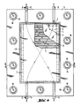
- FIG. 4 shows a plan view in the direction of arrow IV in FIGS. 1, 2 and 3.
- the cell consists of two trough-like metal half-shells (1) and (2).
- a perforated or slotted plate (3) perforated plate, expanded metal, or the like
- the plate (3) serves as an anode.
- a sheet (5) as the cathode, which is connected to the trough (2) via corrugated strips (6).
- the cathode consists of a simple sheet metal, sheet metal strips, perforated sheet metal, expanded metal or a sheet metal blind, preferably a sheet metal sheet.
- Anode tub (1) and cathode tub (2) are separated from each other by a current-permeable, hydraulically sealing partition (7) and seals (8) and (9). They are held together by two insulated steel frames (10) and (11). The screws (16) are insulated by means of plastic bushings (17) and plastic washers (18). There is an inlet pipe (12) for the anolyte on the underside of the anode tub (1), and an inlet pipe (14) for the catholyte on the cathode tub (2). The exhaust pipes (13) and (15) are located on the top of the trays (1) and (2).
- Figure 2 also shows the position of the corrugated strips (4) and (6) and the offset attachment of the inlet pipes (12) and (14).
- the circumferential steel frame (11) can finally be seen from FIGS. 3 and 4.
- the anode tub (1) and the corrugated strips (4) consist of titanium, while the cathode tray (2) and the corrugated strips (6) consist of nickel or a nickel alloy, for example ®Hastelloy.
- valve metals titanium, tantalum, vanadium and zirconium already used in chlor-alkali electrolysis are also suitable as materials for the anode (3) under the aggressive conditions of chromic acid electrolysis. Under anodic current load, these metals form a coherent oxide film on their surface, which protects the base material. If the surface of the anodes is not activated, the oxide layer formed prevents further current flow. Suitable activation layers for these metals for the chromic acid electrolysis are only electron-conducting oxides which have a high overvoltage in relation to oxygen, for example lead dioxide, manganese dioxide, tin dioxide, tantalum oxides or iridium oxides.
- One of the highest surge voltages for oxygen is characterized by lead dioxide, which is preferred. This results in the anodic electrochemical reaction on a titanium anode coated with PbO2 at current densities of 200 A / m2 to 2500 A / m2 current yields between 96% and 88%.
- Nickel and nickel alloys are suitable as materials for the cathode (5).
- sulfuric acid as the catholyte
- the reaction equation Discharges protons at the cathode and develops hydrogen, which leaves the cathode space in gaseous form.
- nickel is only resistant to 10 to 35% sulfuric acid if it is cathodically polarized. It must therefore be prevented that the nickel cathodes are exposed to sulfuric acid when de-energized.
- the hydrogen overvoltage on nickel is relatively low at 0.42 V at a current density of 100 A / m2, compared to quite high on lead under the same conditions at 1.09 v.
- the consequence of this is that when nickel is used as the cathode, a correspondingly lower cell voltage results.
- cation-active ion exchange membranes made of perfluorinated polymers with sulfonyl groups have proven their worth. They show excellent durability and selectivity in the electrolytes used up to temperatures of 110 ° C. The use of such membranes makes it possible to collect the cathodically developed hydrogen separately and to use it further.
- the electrolytic cell to be used and assembled according to the invention can be operated after filling catholyte into the cathode compartment and anolyte into the anode compartment and after pressing the power supply lines of a rectifier onto the anode tub and cathode tub rear wall.
- the continuous supply of catholyte and anolyte from storage tanks takes place via pumps at the lower end of the electrode space.
- the electrolyte leaves the cell.
- the anolyte with the desired composition is passed on for further use, the catholyte is continuously circulated through a buffer container and is concentrated again from time to time.
- the undesirable, to a small extent, developing oxygen (due to water decomposition) at the anode ensures sufficient mixing of the anolyte and supports the diffusion of Cr3+ to the anode surface.
- This effect can be intensified by additionally blowing inert gas into the anode compartment.
- This electrolysis cell is preferably not operated individually. Rather, multiple cells are pressed together in a cell frame by means of a pressing device rear wall to rear wall. This means that the current introduced at the beginning of the cell package with copper bars can flow through all cells and is derived from copper bars at the end of the package. Special contact strips ensure good current transfer between the cells. If the cells are operated in this way, a bipolar cell is present. All individual elements are connected in series.
- the concentration in the anolyte is 20 to 200, preferably 100 to 200, in particular 130 to 170 g / dm3 total CrO3 and 100 to 600, preferably 300 to 600, in particular 450 to 550 g / cm3 H2SO4.
- the catholyte contains 50 to 500, preferably 300 to 350 g / dm3 H2SO4.
- the electrolysis is carried out at a temperature of 40 to 110, preferably 80 to 110 ° C. and a current density of 100 to 2500, preferably 500 to 2500 A / m2.
- the electrolysis was carried out in a round laboratory membrane cell, which was composed of 2 glass dishes and was flange-sealed with two PTFE O-rings.
- the two glass bowls formed the cathode and anode space. They were separated by a polymer membrane made of a perfluorinated polymer, which was clamped between the two O-rings.
- the two circular electrodes were held eccentrically, the DC supply was via these holders.
- the spacing of the anode and cathode could be changed in relation to each other and to the membrane.
- Anolyte and catholyte were heated in the two cell halves with heating rods to 90 ° C and kept constant at this temperature during the electrolysis.
- the cathode consisted of non-activated nickel expanded metal, the anode made of titanium expanded metal, which was coated on all sides with electrodeposited PbO2.
- the cathode-anode distance was 8 mm.
- the catholyte was circulated through the cathode compartment with a constant throughput of 9 cm3 / h at all current densities.
- the electrolysis data obtained are shown in Table 1.
- a titanium expanded metal anode activated with a tantalum oxide / iridium oxide mixture was tested for suitability in a second glass cell, the structure of which corresponded completely to the cell described above.
Landscapes
- Chemical & Material Sciences (AREA)
- Engineering & Computer Science (AREA)
- Chemical Kinetics & Catalysis (AREA)
- Electrochemistry (AREA)
- Materials Engineering (AREA)
- Metallurgy (AREA)
- Organic Chemistry (AREA)
- Inorganic Chemistry (AREA)
- Electrolytic Production Of Non-Metals, Compounds, Apparatuses Therefor (AREA)
- Electrodes For Compound Or Non-Metal Manufacture (AREA)
- Electrolytic Production Of Metals (AREA)
- Inorganic Compounds Of Heavy Metals (AREA)
Applications Claiming Priority (2)
| Application Number | Priority Date | Filing Date | Title |
|---|---|---|---|
| DE3940978 | 1989-12-12 | ||
| DE3940978A DE3940978A1 (de) | 1989-12-12 | 1989-12-12 | Verfahren zur elektrochemischen regenerierung von chromschwefelsaeure |
Publications (2)
| Publication Number | Publication Date |
|---|---|
| EP0436146A1 true EP0436146A1 (fr) | 1991-07-10 |
| EP0436146B1 EP0436146B1 (fr) | 1994-04-20 |
Family
ID=6395298
Family Applications (1)
| Application Number | Title | Priority Date | Filing Date |
|---|---|---|---|
| EP90123633A Expired - Lifetime EP0436146B1 (fr) | 1989-12-12 | 1990-12-08 | Procédé de régénération électrochimique d'acide chromosulfurique |
Country Status (8)
| Country | Link |
|---|---|
| US (1) | US5045162A (fr) |
| EP (1) | EP0436146B1 (fr) |
| JP (1) | JPH05238736A (fr) |
| DE (2) | DE3940978A1 (fr) |
| DK (1) | DK0436146T3 (fr) |
| ES (1) | ES2054203T3 (fr) |
| IE (1) | IE65467B1 (fr) |
| PT (1) | PT96157A (fr) |
Families Citing this family (13)
| Publication number | Priority date | Publication date | Assignee | Title |
|---|---|---|---|---|
| DE4315411C2 (de) * | 1993-05-10 | 1995-04-27 | Lpw Anlagen Gmbh | Verfahren zur Regenerierung von verbrauchten Chromsäurelösungen |
| DE4419683C2 (de) * | 1994-06-06 | 2000-05-04 | Eilenburger Elektrolyse & Umwelttechnik Gmbh | Bipolare Filterpressenzelle für anodische Oxidationen an Platin |
| DE19519177C2 (de) * | 1995-05-24 | 1999-05-12 | Warnecke Hans Joachim Prof Dr | Verfahren und Vorrichtung zur Abfall-CSB-Wert-Verminderung |
| AT409764B (de) * | 1998-03-06 | 2002-11-25 | Treibacher Ind Ag | Verfahren zur oxidation von vanadium |
| NZ331053A (en) * | 1998-07-21 | 2002-12-20 | Osmose New Zealand | Process for electrochemical generation of higher oxidate state values from lower oxidation state values above zero of transition metal(s) [eg; |
| FR2791662B1 (fr) * | 1999-04-01 | 2001-06-22 | Conservatoire Nat Arts | Procede de traitement electrochimique d'effluents, notamment d'effluents de tannerie, comprenant des sels de chrome |
| US6468414B1 (en) | 2001-02-16 | 2002-10-22 | Hydro-Quebec | Method of purification of a redox mediator before electrolytic regeneration thereof |
| GB2399349A (en) * | 2003-03-13 | 2004-09-15 | Kurion Technologies Ltd | Regeneration of chromic acid etching and pickling baths |
| JP3836833B2 (ja) * | 2003-11-11 | 2006-10-25 | 山口 嘉春 | 水素と酸素の混合ガス発生装置およびその電解槽 |
| DE102004023161A1 (de) * | 2004-05-07 | 2005-11-24 | Eilenburger Elektrolyse- Und Umwelttechnik Gmbh | Elektrolysezelle mit Mehrlagen-Streckmetall-Kathoden |
| CN108103521B (zh) * | 2017-12-22 | 2019-10-15 | 四川省银河化学股份有限公司 | 一种提高电解法制备铬酸酐品质的方法 |
| WO2024234026A1 (fr) * | 2023-05-17 | 2024-11-21 | Andritz Ag | Cellule électrolytique, bloc électrolytique comprenant plusieurs cellules électrolytiques correspondantes et dispositif électrolytique doté de plusieurs cellules électrolytiques correspondantes |
| AT527859A1 (de) * | 2023-12-20 | 2025-07-15 | Andritz Ag Maschf | Elektrolyseur zur alkalischen Wasserstoffelektrolyse |
Citations (5)
| Publication number | Priority date | Publication date | Assignee | Title |
|---|---|---|---|---|
| FR2219806A1 (en) * | 1973-03-02 | 1974-09-27 | Basf Ag | Diaphragm cell for chromic-sulphuric acid prodn. - with membrane near cathode and high anode-cathode surface ratio |
| US4006067A (en) * | 1973-03-05 | 1977-02-01 | Gussack Mark C | Oxidation-reduction process |
| FR2354399A1 (fr) * | 1976-06-11 | 1978-01-06 | Sarel | Compartiment cathodique pour la regeneration electrolytique de solutions sulfo-chromiques et/ou phospho-chromiques |
| EP0189535A1 (fr) * | 1985-01-16 | 1986-08-06 | Uhde GmbH | Appareil d'électrolyse |
| WO1986005215A1 (fr) * | 1985-02-27 | 1986-09-12 | Elin-Union Aktiengesellschaft Für Elektrische Indu | Procede d'oxydation electrochimique de solutions de chrome iii dans l'acide sulfurique en solutions de chrome vi |
Family Cites Families (1)
| Publication number | Priority date | Publication date | Assignee | Title |
|---|---|---|---|---|
| US3761369A (en) * | 1971-10-18 | 1973-09-25 | Electrodies Inc | Process for the electrolytic reclamation of spent etching fluids |
-
1989
- 1989-12-12 DE DE3940978A patent/DE3940978A1/de not_active Withdrawn
-
1990
- 1990-10-31 US US07/606,437 patent/US5045162A/en not_active Expired - Fee Related
- 1990-12-08 DE DE59005450T patent/DE59005450D1/de not_active Expired - Fee Related
- 1990-12-08 ES ES90123633T patent/ES2054203T3/es not_active Expired - Lifetime
- 1990-12-08 EP EP90123633A patent/EP0436146B1/fr not_active Expired - Lifetime
- 1990-12-08 DK DK90123633.1T patent/DK0436146T3/da active
- 1990-12-11 IE IE446490A patent/IE65467B1/en not_active IP Right Cessation
- 1990-12-11 JP JP2401408A patent/JPH05238736A/ja not_active Withdrawn
- 1990-12-11 PT PT96157A patent/PT96157A/pt unknown
Patent Citations (5)
| Publication number | Priority date | Publication date | Assignee | Title |
|---|---|---|---|---|
| FR2219806A1 (en) * | 1973-03-02 | 1974-09-27 | Basf Ag | Diaphragm cell for chromic-sulphuric acid prodn. - with membrane near cathode and high anode-cathode surface ratio |
| US4006067A (en) * | 1973-03-05 | 1977-02-01 | Gussack Mark C | Oxidation-reduction process |
| FR2354399A1 (fr) * | 1976-06-11 | 1978-01-06 | Sarel | Compartiment cathodique pour la regeneration electrolytique de solutions sulfo-chromiques et/ou phospho-chromiques |
| EP0189535A1 (fr) * | 1985-01-16 | 1986-08-06 | Uhde GmbH | Appareil d'électrolyse |
| WO1986005215A1 (fr) * | 1985-02-27 | 1986-09-12 | Elin-Union Aktiengesellschaft Für Elektrische Indu | Procede d'oxydation electrochimique de solutions de chrome iii dans l'acide sulfurique en solutions de chrome vi |
Also Published As
| Publication number | Publication date |
|---|---|
| IE904464A1 (en) | 1991-06-19 |
| JPH05238736A (ja) | 1993-09-17 |
| US5045162A (en) | 1991-09-03 |
| PT96157A (pt) | 1991-09-30 |
| EP0436146B1 (fr) | 1994-04-20 |
| DE59005450D1 (de) | 1994-05-26 |
| IE65467B1 (en) | 1995-11-01 |
| DE3940978A1 (de) | 1991-06-13 |
| ES2054203T3 (es) | 1994-08-01 |
| DK0436146T3 (da) | 1994-08-08 |
Similar Documents
| Publication | Publication Date | Title |
|---|---|---|
| DE69108018T2 (de) | Vorrichtung zur herstellung von chlorsäure und verchlorsäure. | |
| EP0428171B1 (fr) | Cellule d'électrolyse pour la production de composés peroxo et perhalogénés | |
| EP0989206B1 (fr) | Cellule d'électrolyse et son utilisation | |
| DE69016459T2 (de) | Elektrochemischer chlordioxidgenerator. | |
| DE3051012C2 (fr) | ||
| DE2445579C2 (de) | Elektrolytische Zelle | |
| DE2735239C2 (de) | Monopolare Membran- oder Diaphragmaelektrolysezelle | |
| EP0095997B1 (fr) | Procédé pour la production de l'eau oxygénée et son utilisation | |
| EP0436146B1 (fr) | Procédé de régénération électrochimique d'acide chromosulfurique | |
| DE2251660B2 (de) | Sulfonierte copolymere als membranen fuer die chloralkalielektrolyse | |
| WO2016134952A1 (fr) | Dépôt d'un électrocatalyseur contenant du cuivre et dégageant des hydrocarbures sur des substrats sans cuivre | |
| DE4438275B4 (de) | Elektrolysezelle und Verfahren zur Elektrolyse einer wässrigen Kochsalzlösung | |
| DD140262A5 (de) | Verfahren zur kontinuierlichen herstellung von chlor | |
| EP0168600A2 (fr) | Electrolyseur bipolaire avec cathode à diffusion de gaz | |
| DE2260771B2 (de) | Verfahren zur herstellung von alkalihydroxid und chlor oder wasserstoff und chlor durch elektrolyse | |
| DE68904002T2 (de) | Verfahren zur elektrolytischen metallbeschichtung eines metallsubstrates in form eines streifens und vorrichtung dazu. | |
| DE3401812C2 (de) | Elektrolysezelle | |
| DE2125941C3 (de) | Bipolare Einheit und damit aufgebaute elektrolytische Zelle | |
| DE2454827C3 (de) | Elektrolysezelle | |
| DE1417194A1 (de) | Anode fuer Elektrolysezellen | |
| DE2451846A1 (de) | Verfahren zur elektrolytischen herstellung von metallhydroxidloesungen | |
| DE2947789C2 (de) | Verfahren zur elektrolytischen Gewinnung von Wasserstoff und dafür geeignete Elektrolysezelle | |
| DE2828621C2 (fr) | ||
| DD250138A5 (de) | Elektrolytische zelle | |
| DE2719759B2 (de) | Elektrolysezelle |
Legal Events
| Date | Code | Title | Description |
|---|---|---|---|
| PUAI | Public reference made under article 153(3) epc to a published international application that has entered the european phase |
Free format text: ORIGINAL CODE: 0009012 |
|
| AK | Designated contracting states |
Kind code of ref document: A1 Designated state(s): BE DE DK ES FR GB GR IT LU NL |
|
| 17P | Request for examination filed |
Effective date: 19910920 |
|
| 17Q | First examination report despatched |
Effective date: 19930111 |
|
| GRAA | (expected) grant |
Free format text: ORIGINAL CODE: 0009210 |
|
| AK | Designated contracting states |
Kind code of ref document: B1 Designated state(s): BE DE DK ES FR GB GR IT LU NL |
|
| REF | Corresponds to: |
Ref document number: 59005450 Country of ref document: DE Date of ref document: 19940526 |
|
| ITF | It: translation for a ep patent filed | ||
| GBT | Gb: translation of ep patent filed (gb section 77(6)(a)/1977) |
Effective date: 19940627 |
|
| REG | Reference to a national code |
Ref country code: ES Ref legal event code: FG2A Ref document number: 2054203 Country of ref document: ES Kind code of ref document: T3 |
|
| REG | Reference to a national code |
Ref country code: DK Ref legal event code: T3 |
|
| ET | Fr: translation filed | ||
| REG | Reference to a national code |
Ref country code: GR Ref legal event code: FG4A Free format text: 3012060 |
|
| PLBE | No opposition filed within time limit |
Free format text: ORIGINAL CODE: 0009261 |
|
| STAA | Information on the status of an ep patent application or granted ep patent |
Free format text: STATUS: NO OPPOSITION FILED WITHIN TIME LIMIT |
|
| 26N | No opposition filed | ||
| PGFP | Annual fee paid to national office [announced via postgrant information from national office to epo] |
Ref country code: NL Payment date: 19971130 Year of fee payment: 8 |
|
| PGFP | Annual fee paid to national office [announced via postgrant information from national office to epo] |
Ref country code: DK Payment date: 19971208 Year of fee payment: 8 |
|
| PGFP | Annual fee paid to national office [announced via postgrant information from national office to epo] |
Ref country code: ES Payment date: 19971209 Year of fee payment: 8 |
|
| PGFP | Annual fee paid to national office [announced via postgrant information from national office to epo] |
Ref country code: GR Payment date: 19971219 Year of fee payment: 8 |
|
| PGFP | Annual fee paid to national office [announced via postgrant information from national office to epo] |
Ref country code: LU Payment date: 19971224 Year of fee payment: 8 |
|
| PGFP | Annual fee paid to national office [announced via postgrant information from national office to epo] |
Ref country code: BE Payment date: 19971230 Year of fee payment: 8 |
|
| PGFP | Annual fee paid to national office [announced via postgrant information from national office to epo] |
Ref country code: GB Payment date: 19981112 Year of fee payment: 9 Ref country code: FR Payment date: 19981112 Year of fee payment: 9 |
|
| PG25 | Lapsed in a contracting state [announced via postgrant information from national office to epo] |
Ref country code: LU Free format text: LAPSE BECAUSE OF NON-PAYMENT OF DUE FEES Effective date: 19981208 Ref country code: DK Free format text: LAPSE BECAUSE OF NON-PAYMENT OF DUE FEES Effective date: 19981208 |
|
| PG25 | Lapsed in a contracting state [announced via postgrant information from national office to epo] |
Ref country code: GR Free format text: LAPSE BECAUSE OF NON-PAYMENT OF DUE FEES Effective date: 19981231 Ref country code: BE Free format text: LAPSE BECAUSE OF NON-PAYMENT OF DUE FEES Effective date: 19981231 |
|
| BERE | Be: lapsed |
Owner name: HOECHST A.G. Effective date: 19981231 |
|
| PG25 | Lapsed in a contracting state [announced via postgrant information from national office to epo] |
Ref country code: NL Free format text: LAPSE BECAUSE OF NON-PAYMENT OF DUE FEES Effective date: 19990701 |
|
| NLV4 | Nl: lapsed or anulled due to non-payment of the annual fee |
Effective date: 19990701 |
|
| PGFP | Annual fee paid to national office [announced via postgrant information from national office to epo] |
Ref country code: DE Payment date: 19991113 Year of fee payment: 10 |
|
| PG25 | Lapsed in a contracting state [announced via postgrant information from national office to epo] |
Ref country code: GB Free format text: LAPSE BECAUSE OF NON-PAYMENT OF DUE FEES Effective date: 19991208 |
|
| PG25 | Lapsed in a contracting state [announced via postgrant information from national office to epo] |
Ref country code: ES Free format text: LAPSE BECAUSE OF NON-PAYMENT OF DUE FEES Effective date: 19991209 |
|
| REG | Reference to a national code |
Ref country code: FR Ref legal event code: TP |
|
| GBPC | Gb: european patent ceased through non-payment of renewal fee |
Effective date: 19991208 |
|
| PG25 | Lapsed in a contracting state [announced via postgrant information from national office to epo] |
Ref country code: FR Free format text: LAPSE BECAUSE OF NON-PAYMENT OF DUE FEES Effective date: 20000831 |
|
| REG | Reference to a national code |
Ref country code: DK Ref legal event code: EBP |
|
| REG | Reference to a national code |
Ref country code: FR Ref legal event code: ST |
|
| PG25 | Lapsed in a contracting state [announced via postgrant information from national office to epo] |
Ref country code: DE Free format text: LAPSE BECAUSE OF NON-PAYMENT OF DUE FEES Effective date: 20011002 |
|
| REG | Reference to a national code |
Ref country code: ES Ref legal event code: FD2A Effective date: 20000114 |
|
| PG25 | Lapsed in a contracting state [announced via postgrant information from national office to epo] |
Ref country code: IT Free format text: LAPSE BECAUSE OF NON-PAYMENT OF DUE FEES Effective date: 20051208 |