EP0436223A2 - Programmateur intelligent - Google Patents
Programmateur intelligent Download PDFInfo
- Publication number
- EP0436223A2 EP0436223A2 EP90125604A EP90125604A EP0436223A2 EP 0436223 A2 EP0436223 A2 EP 0436223A2 EP 90125604 A EP90125604 A EP 90125604A EP 90125604 A EP90125604 A EP 90125604A EP 0436223 A2 EP0436223 A2 EP 0436223A2
- Authority
- EP
- European Patent Office
- Prior art keywords
- timer
- setting
- functioning
- audio sources
- functioning conditions
- Prior art date
- Legal status (The legal status is an assumption and is not a legal conclusion. Google has not performed a legal analysis and makes no representation as to the accuracy of the status listed.)
- Withdrawn
Links
Images

Classifications
-
- G—PHYSICS
- G05—CONTROLLING; REGULATING
- G05B—CONTROL OR REGULATING SYSTEMS IN GENERAL; FUNCTIONAL ELEMENTS OF SUCH SYSTEMS; MONITORING OR TESTING ARRANGEMENTS FOR SUCH SYSTEMS OR ELEMENTS
- G05B19/00—Program-control systems
- G05B19/02—Program-control systems electric
- G05B19/04—Program control other than numerical control, i.e. in sequence controllers or logic controllers
- G05B19/10—Program control other than numerical control, i.e. in sequence controllers or logic controllers using selector switches
- G05B19/106—Program control other than numerical control, i.e. in sequence controllers or logic controllers using selector switches for selecting a program, variable or parameter
- G05B19/108—Program control other than numerical control, i.e. in sequence controllers or logic controllers using selector switches for selecting a program, variable or parameter characterised by physical layout of switches; switches co-operating with display; use of switches in a special way
Definitions
- This invention relates to an intelligent timer for an audio system in which a tuner, a compact disk player, a laser disk player, a tape deck and so forth are incorporated, and particularly to improvement in setting of such timer.
- an intelligent timer for an acoustic system which includes several audio-visual sources, which comprises timer setting means for effecting setting of a timer program, functioning condition detecting means for detecting functioning conditions of the audio sources, and memory means for storing functioning conditions of a particular one of the audio sources which is in an operative condition when setting of the timer is started by way of the timer setting means as functioning conditions in which the particular one audio source should be upon operation of the timer.
- an apparatus serving as an audio source which is to be used upon operation of the timer is first set into functioning conditions in which it should be upon operation of the timer and then only setting of a starting point of time of the timer is executed, then functioning conditions of a particular one of the audio sources which is in an operative condition when setting of the timer is started by way of the timer setting means are automatically stored into the memory means as functioning conditions in which the particular one audio source should be upon operation of the timer. Accordingly, functioning conditions of the audio source upon operation of the timer can be confirmed in advance and, a procedure for setting of the timer is simplified and setting of such functioning conditions is effected in a very short period of time without an error.
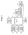
- the timer shown includes a controlling circuit 1 which serves as a central processing unit.
- Various other components are connected to the controlling circuit 1 and include a plurality of manually operable switches 2 for entering operation information by manual operation thereof, an A/B switch 3 for alternatively selecting one of two modes for which contents of timer setting are set in advance, a timer setting means 4 including several manually operable keys not shown for cooperating with the controlling circuit 1 to set a timer program, a plurality of, that is, n, input or audio sources 5 (51 to 5 n ) which may include a tuner, a compact disk player, a laser disk player, a tape deck and so forth not shown, a random access memory (RAM) or storage medium 6 serving as memory means for storing therein functioning conditions of the audio sources 51 to 5 n upon setting of the timer, a display unit 7 for displaying thereon various information including a time, a mode, a channel and so forth, a pre
- the controlling circuit 1 receives various information including discrimination information, operation information, condition information and so forth from the manually operable keys 2, A/B switch 3, timer setting means 4, input sources 51 to 5 n , RAM 6 and preamplifier 8, determines operation of the input sources 51 to 5 n , RAM 6, display unit 7 and preamplifier 8, and also executes control of inputting/outputting of various information.
- Functioning condition detecting means for detecting functioning conditions of various input sources is included in the controlling circuit 1.
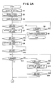
- FIG. 2 illustrates operation of the timer, particularly, a flow of operations for setting a wake up time.
- the controlling circuit 1 first waits at step S1 until a SET key not shown of the timer setting means 4 is entered. After the SET key is entered, the controlling circuit 1 recalls from the RAM 6 and temporarily stores into an internal temporary memory area thereof, at step S2, various information which has been detected by the functioning condition detecting means immediately before the present routine is entered and which has been stored in advance from the input sources 5 into the RAM 6 by way of the controlling circuit 1.
- Such information includes, where the input source is a compact disk player, information of whether the play is a random play or a repeat play, what number piece the piece is, whether the play is a play corresponding to a sub code, whether the display is a remaining time display, and so forth, or where the input source is a tuner, information of whether the broadcasting is FM broadcasting, AM broadcasting or TV broadcasting, what channel the selected station is, whether the input source is in a mute condition or in an automatic blending condition, or where the input source is a television set, information of degrees of colors, tint, brightness and so forth.
- information which has been detected by the functioning condition detecting means immediately before entry of the present routine and has been stored in advance from the preamplifier 8 and the main amplifier 9 by way of the controlling circuit 1 is recalled from the RAM 6.
- Such information from the preamplifier 8 includes mode information including information of a sound quality, a surround mode, a sound field effect, a function and so forth while the information from the main amplifier 9 includes information of a sound volume and information of a selected output terminal of the main amplifier 9.
- a timer selecting mode is entered at step S3.
- entry of the SET key is waited for a fixed period of time, for example, for 5 seconds at steps S4 and S5.
- step S6 the control sequence advances from step S5 to step S6 to enter a timer checking mode.
- timer checking mode various items of set contents of the timer are successively displayed on the display unit 7 each for a fixed period of time, for example, for 5 seconds. After then, the control sequence comes to an end of the present routine.
- step S7 a display of a numeral on the display unit 7 is successively changed by manual operation of a plus key and/or a minus key of the timer setting means 4. Then, if the SET key is entered at step S8 when a desired "hour” value is displayed on the display unit 7, the value thus displayed is set or settled as the "hour” for a starting time, and subsequently, the control sequence advances to step S9 to enter a "minute” setting mode.
- a "minute” display is changed by means of the plus key and/or the minus key similarly as in the "hour” setting mode at step S7, and when the SET key is entered at step S10, a numeral displayed on the display unit 7 then is set or settled as the "minute” for a starting time.
- the starting time that is, the "hour” and the "minute” for a starting time, are settled in this manner.
- an "hour" setting mode for an ending time or off time is entered.
- a time obtained by adding a fixed time, for example, one hour, to the starting time is initially set as an ending time.
- the time obtained by such addition is stored into a register therefor in the temporary storage area of the controlling circuit 1 and also displayed on the display unit 7.
- the controlling circuit 1 waits in this condition, at step S11, for 5 seconds until the plus key or minus key of the timer setting means 4 is entered after the SET key is entered at step S10. If neither the plus key nor the minus key is entered within 5 seconds at steps S11 and S12, setting of an "hour” for an ending time is completed immediately and a "minute” setting mode is entered at step S15. Consequently, the initially set value of the "hour” described above is maintained as the "hour” for an ending time.
- step S12 the sequence advances to step S13 at which the value of the "hour" for an ending time displayed on the display unit 7 is incremented or decremented each time plus key or the minus key is entered, and then if the SET key is entered at step S14 when a desired value is displayed on the display unit 7, the value is set or settled as the "hour" for an ending time, and the control sequence subsequently enters a "minute” setting mode.
- the initially set value of the "minute” for an ending time is changed each time the plus key or minus key is entered at step S17, and when the SET key is entered at step S18, the value of the "minute” displayed on the display unit 7 is set or settled as the "minute” for an ending time.
- the ending time that is, the "hour” and the "minute” for an ending time, are set or settled in this manner. After then, an operation selecting mode is entered.
- the controlling circuit 1 waits, at step S19, for 5 seconds until either the plus key or the minus key is entered at step S20. If the plus key or minus key is entered within 5 seconds at step S20, then selection of a mode of operation is effected subsequently at step S21. In such selection of a mode, one of the two modes A and B in which the contents described hereinabove are set in advance can be selected, and when the SET key is entered after the mode A or B is selected, that is, after the A/B switch 3 is operated to the A side or B side, the selection is finally settled, that is, the mode A or the mode B is set. Then, information or contents of operation relating to the selected mode A or B are changed accordingly at step S23.
- Such contents of operation which may be changed at step S23 may include, for example, a function, a sound quality mode, a surround mode and a "volume” position.
- the control sequence advances to step S24 at which the contents of operation or data thus set in the flow of operation described above including the "hour” and “minute” for a starting time, the "hour” and “minute” for an ending time and the contents of operation obtained at step S23 are stored into the RAM 6.
- step S19 the control sequence directly advance to step S24 at which the contents of operation set in the flow of operations described above are stored into the RAM 6.
- step S24 the contents of operation set in the flow of operations described above are stored into the RAM 6.
- control sequence subsequently advances from step S24 to step S25 to enter a timer checking mode.
- timer checking mode at step S25, the finally settled or set contents of operation are successively displayed each for 5 seconds on the display unit 7. After then, the control sequence comes to an end of the present routine.
Landscapes
- Physics & Mathematics (AREA)
- General Physics & Mathematics (AREA)
- Engineering & Computer Science (AREA)
- Automation & Control Theory (AREA)
- Electric Clocks (AREA)
Applications Claiming Priority (2)
| Application Number | Priority Date | Filing Date | Title |
|---|---|---|---|
| JP286/90 | 1990-01-05 | ||
| JP28690A JPH03205588A (ja) | 1990-01-05 | 1990-01-05 | インテリジェント・タイマ |
Publications (2)
| Publication Number | Publication Date |
|---|---|
| EP0436223A2 true EP0436223A2 (fr) | 1991-07-10 |
| EP0436223A3 EP0436223A3 (en) | 1992-03-18 |
Family
ID=11469662
Family Applications (1)
| Application Number | Title | Priority Date | Filing Date |
|---|---|---|---|
| EP19900125604 Withdrawn EP0436223A3 (en) | 1990-01-05 | 1990-12-27 | Intelligent timer |
Country Status (2)
| Country | Link |
|---|---|
| EP (1) | EP0436223A3 (fr) |
| JP (1) | JPH03205588A (fr) |
Family Cites Families (3)
| Publication number | Priority date | Publication date | Assignee | Title |
|---|---|---|---|---|
| JPS5861423A (ja) * | 1981-10-08 | 1983-04-12 | Yuuseidaijin | 郵便用秤システム |
| JPS59153194A (ja) * | 1983-02-21 | 1984-09-01 | Nec Corp | プログラマブル・タイマ |
| JPH073471Y2 (ja) * | 1985-09-19 | 1995-01-30 | ソニー株式会社 | 映像信号記録装置 |
-
1990
- 1990-01-05 JP JP28690A patent/JPH03205588A/ja active Pending
- 1990-12-27 EP EP19900125604 patent/EP0436223A3/en not_active Withdrawn
Also Published As
| Publication number | Publication date |
|---|---|
| EP0436223A3 (en) | 1992-03-18 |
| JPH03205588A (ja) | 1991-09-09 |
Similar Documents
| Publication | Publication Date | Title |
|---|---|---|
| US4162513A (en) | Television system scheduler | |
| US5285265A (en) | Display apparatus informing of programmed recording | |
| US5270829A (en) | Automatically reserve-recording and reserve-playing back a broadcasted program | |
| US5237319A (en) | Remote control device with learning function | |
| JPH0983897A (ja) | テレビ受信機 | |
| US4796107A (en) | Apparatus for reserving programs at various recording tape running speeds | |
| US6754436B1 (en) | Apparatus for timer recording of a program and method for timer recording of a program | |
| JP2522311B2 (ja) | 電子機器のサ−ビスモ−ド設定方法 | |
| KR0138746B1 (ko) | 메모리된 채널 표시방법 | |
| US5771329A (en) | Recording mode control method for combined video appliances | |
| KR0127764B1 (ko) | 캠코더의 특성조정장치 및 그 조정방법 | |
| EP0436223A2 (fr) | Programmateur intelligent | |
| EP1211814B1 (fr) | Récepteur radio | |
| KR100383129B1 (ko) | 영상기기의초기채널지정장치와방법 | |
| KR970004635B1 (ko) | 씨디 내장 티브이씨알의 영상 및 음성 기록 방법 및 회로 | |
| KR0181895B1 (ko) | 복합영상신호기록재생장치의 온 타임 기능 수행 방법 | |
| KR0136023B1 (ko) | 텔레비전의 osd표시시간 설정제어장치 | |
| JPS6161577A (ja) | テレビジョン信号受信装置 | |
| KR960015133B1 (ko) | 티브이의 비디오 모드시 파워 온 음성 경보 방법 | |
| KR890001905B1 (ko) | 제어장치 | |
| KR0123746B1 (ko) | 더블데크 자기기록/재생장치의 기록소스 자동선택방법 | |
| JP2534912Y2 (ja) | 音響機器の入力切換装置 | |
| JP2829162B2 (ja) | リモートコントロール送信器 | |
| KR0149252B1 (ko) | 비디오 카세트 레코더에서의 예약 녹화 방법 | |
| KR100327258B1 (ko) | 채널 디스플레이 장치 및 방법 |
Legal Events
| Date | Code | Title | Description |
|---|---|---|---|
| PUAI | Public reference made under article 153(3) epc to a published international application that has entered the european phase |
Free format text: ORIGINAL CODE: 0009012 |
|
| AK | Designated contracting states |
Kind code of ref document: A2 Designated state(s): DE FR GB |
|
| PUAL | Search report despatched |
Free format text: ORIGINAL CODE: 0009013 |
|
| AK | Designated contracting states |
Kind code of ref document: A3 Designated state(s): DE FR GB |
|
| 17P | Request for examination filed |
Effective date: 19920610 |
|
| STAA | Information on the status of an ep patent application or granted ep patent |
Free format text: STATUS: THE APPLICATION IS DEEMED TO BE WITHDRAWN |
|
| 18D | Application deemed to be withdrawn |
Effective date: 19940701 |