EP0436232A1 - Applicateur pour l'implantation d'une lentille artificielle - Google Patents
Applicateur pour l'implantation d'une lentille artificielle Download PDFInfo
- Publication number
- EP0436232A1 EP0436232A1 EP90125806A EP90125806A EP0436232A1 EP 0436232 A1 EP0436232 A1 EP 0436232A1 EP 90125806 A EP90125806 A EP 90125806A EP 90125806 A EP90125806 A EP 90125806A EP 0436232 A1 EP0436232 A1 EP 0436232A1
- Authority
- EP
- European Patent Office
- Prior art keywords
- lens
- instrument according
- jaws
- instrument
- slide
- Prior art date
- Legal status (The legal status is an assumption and is not a legal conclusion. Google has not performed a legal analysis and makes no representation as to the accuracy of the status listed.)
- Withdrawn
Links
- 238000002513 implantation Methods 0.000 title description 6
- 239000002775 capsule Substances 0.000 claims abstract description 22
- 230000003287 optical effect Effects 0.000 claims description 15
- 230000002093 peripheral effect Effects 0.000 claims 1
- 241000219739 Lens Species 0.000 description 126
- 238000004873 anchoring Methods 0.000 description 6
- 210000001015 abdomen Anatomy 0.000 description 5
- 229920003229 poly(methyl methacrylate) Polymers 0.000 description 4
- 239000004926 polymethyl methacrylate Substances 0.000 description 4
- 208000002177 Cataract Diseases 0.000 description 3
- 230000006835 compression Effects 0.000 description 3
- 238000007906 compression Methods 0.000 description 3
- 239000007943 implant Substances 0.000 description 3
- 238000001356 surgical procedure Methods 0.000 description 3
- 240000004322 Lens culinaris Species 0.000 description 2
- 238000010276 construction Methods 0.000 description 2
- 238000006073 displacement reaction Methods 0.000 description 2
- 239000000463 material Substances 0.000 description 2
- 238000000465 moulding Methods 0.000 description 2
- 238000007493 shaping process Methods 0.000 description 2
- 244000089486 Phragmites australis subsp australis Species 0.000 description 1
- 238000005553 drilling Methods 0.000 description 1
- 230000002349 favourable effect Effects 0.000 description 1
- 229920002379 silicone rubber Polymers 0.000 description 1
- 239000004945 silicone rubber Substances 0.000 description 1
Images



Classifications
-
- A—HUMAN NECESSITIES
- A61—MEDICAL OR VETERINARY SCIENCE; HYGIENE
- A61F—FILTERS IMPLANTABLE INTO BLOOD VESSELS; PROSTHESES; DEVICES PROVIDING PATENCY TO, OR PREVENTING COLLAPSING OF, TUBULAR STRUCTURES OF THE BODY, e.g. STENTS; ORTHOPAEDIC, NURSING OR CONTRACEPTIVE DEVICES; FOMENTATION; TREATMENT OR PROTECTION OF EYES OR EARS; BANDAGES, DRESSINGS OR ABSORBENT PADS; FIRST-AID KITS
- A61F2/00—Filters implantable into blood vessels; Prostheses, i.e. artificial substitutes or replacements for parts of the body; Appliances for connecting them with the body; Devices providing patency to, or preventing collapsing of, tubular structures of the body, e.g. stents
- A61F2/02—Prostheses implantable into the body
- A61F2/14—Eye parts, e.g. lenses or corneal implants; Artificial eyes
- A61F2/16—Intraocular lenses
- A61F2/1662—Instruments for inserting intraocular lenses into the eye
-
- A—HUMAN NECESSITIES
- A61—MEDICAL OR VETERINARY SCIENCE; HYGIENE
- A61F—FILTERS IMPLANTABLE INTO BLOOD VESSELS; PROSTHESES; DEVICES PROVIDING PATENCY TO, OR PREVENTING COLLAPSING OF, TUBULAR STRUCTURES OF THE BODY, e.g. STENTS; ORTHOPAEDIC, NURSING OR CONTRACEPTIVE DEVICES; FOMENTATION; TREATMENT OR PROTECTION OF EYES OR EARS; BANDAGES, DRESSINGS OR ABSORBENT PADS; FIRST-AID KITS
- A61F2/00—Filters implantable into blood vessels; Prostheses, i.e. artificial substitutes or replacements for parts of the body; Appliances for connecting them with the body; Devices providing patency to, or preventing collapsing of, tubular structures of the body, e.g. stents
- A61F2/02—Prostheses implantable into the body
- A61F2/14—Eye parts, e.g. lenses or corneal implants; Artificial eyes
- A61F2/16—Intraocular lenses
- A61F2002/1681—Intraocular lenses having supporting structure for lens, e.g. haptics
- A61F2002/1683—Intraocular lenses having supporting structure for lens, e.g. haptics having filiform haptics
Definitions
- the invention relates to an instrument for implanting an artificial lens with a central optical part and an elastically deformable haptic part into the lens capsule of an eye.
- a cannula is used to tear a central circular opening (capsulorhexis) with a sharp-edged edge into the front wall of the lens capsule, remove the lens nucleus and implant an artificial lens through the capsulorhexis into the lens capsule.
- the anatomical geometry of the capsular bag is preserved and you have favorable optical conditions.
- only certain types of artificial lenses can be inserted into the lens capsule through a central round capsulorhexis, since the lens diameter in the area of the haptic part used for anchoring is necessarily larger than that of the capsulorhexis.
- the mostly used artificial lens according to Sinskey and Kratz has a haptic part in the form of two curved anchoring brackets lying in the main lens plane, which protrude tangentially from the central optical part in a twofold symmetrical arrangement and essentially follow the edge curvature.
- the anchoring brackets can be deformed elastically to such an extent that the lens can be inserted through a central round capsulorhexis.
- the disadvantage is that the elastic expansion of the anchoring bracket in the capsular bag is not homogeneous over the circumference of the optical part of the lens. Deformation of the lens capsule ("American Football") by the anchoring brackets can result in misalignment of the artificial lens and question the success of the operation.
- a preferred material for artificial lenses is PMMA (polymethyl methacrylate), which has excellent physiological tolerance, good optical properties and the elasticity desired for the haptic part.
- PMMA polymethyl methacrylate
- So-called chip lenses are also known in practice. These are intraocular lenses with an optical lens body and a haptic formed integrally therewith, to which arms are connected at a common molding point to the periphery of the lens body and extend in the opposite circumferential direction at a distance around the lens body, between the ends of which there is a gap .
- the object of the invention is to provide an instrument of the type mentioned with which a disk lens or chip lens, preferably made of PMMA, can be implanted into the lens capsule of an eye with one-handed operation through a central, round capsulorhexis of smaller diameter.
- the haptic part of an artificial lens is elastically deformed by the tensioning mechanism in such a way that the lens fits through a central capsulorhexis with a much smaller diameter than the lens diameter.
- the lens is released in a feed movement from the clamping mechanism and implanted through the capsulorhexis into the lens capsule, the deformation of the haptic part being reversed thanks to its elasticity and the lens returning to its original shape.
- the device according to the invention enables cataract surgery in which the lens capsule passes through a central round Kapsulorhexis is opened so that its anatomical geometry is fully preserved. It can be implanted through the capsulorhexis in terms of its haptic and optical properties optimally modeled on the natural lens nucleus without the capsular bag tissue being subject to the risk of damage.
- the diameter of the capsulorhexis essentially only has to correspond to the diameter of the optical part of the lens. For example, it is possible to implant a lens with a diameter of 9 to 10 mm through a capsulorhexis with a diameter of 4 to 6 mm.
- the haptic part of the lens which has a significantly larger diameter than the capsulorhexis in the relaxed state, ensures that the lens is correctly positioned and securely anchored in the capsule bag, which is not or not significantly deformed.
- the clamping mechanism of the instrument according to the invention preferably includes two opposing jaws, between which the lens fits while deforming its haptic part.
- the jaws of the clamping mechanism can be spread out like pliers and closed around the lens in order to deform it to the required extent.
- This variant of the instrument according to the invention which is not very simple in terms of structure and operation, can be used universally for different lens shapes and sizes.
- the lens can be easily inserted into the clamping mechanism preoperatively, and the extent of its deformation can be individually determined on a case-by-case basis.
- the jaws are rigid and at least in sections are designed to converge towards one another.
- the instrument has a suitable holding device for the artificial lens, and it is designed such that the lens can be clamped between and released from the holding device and jaws in a relative movement of the latter.
- the jaws can be located on a slide which is slidably mounted on a guide wire.
- the holding device for the lens is arranged at the end of the guide wire.
- a hook located at the end of the guide wire is recommended, which fits into a positioning opening in the haptic part of the lens.
- a preferred holding device for a chip lens consists of a hook plate. This can have a flat rectangular plate body and a plurality of hooks projecting from it on one side. The hook plate overlaps the molded surface of the feel of a chip lens. Your hooks engage behind the base of the haptic arms, which holds the chip lens securely.
- a holding plate with four hooks arranged in the quadrant is advantageously used for chip lenses, the haptic arms of which are constructed from two radially spaced brackets in the region of the molding point. The hooks reach behind the insert of the brackets and hold the lens at four points so that it cannot rotate.
- the instrument preferably has an elongated handle, with respect to the extended longitudinal axis of which the guide wire can be curved upwards. This design is preferred in terms of handling.
- the slider can have a preferably flat back support which extends essentially parallel to the guide wire and at the end of which there can be a ramp.
- the jaws are preferably arranged in a symmetrical arrangement on both sides of the back support, wherein they extend to at least the height of the guide wire.
- the lens is held on all sides between the back support, jaws and guide wire.
- the jaws are preferably substantially straight. You can form the outer tines of a three-pronged fork, the middle prong of which serves as a back support.
- the jaws have a U profile with a U opening facing one another. This ensures that the lens is securely held and guided between the jaws.
- the U-back of the jaws can be provided with a slot which extends in the longitudinal direction of the jaw and is not continuous at the outer ends of the jaws and through which the haptic part of the lens fits.
- the lens is thus constricted essentially between the outer ends of the jaws, while the lens can bulge out to the side over the length of the jaws, with its haptic part emerging through the slots in the back of the cheek.
- the lens experiences its greatest deformation at the tip of the instrument, which is brought up to the capsulorhexis for implantation of the lens. When released from the instrument, the lens parts released from the jaws unfold and relax optimally.
- the slide of the instrument can be moved between a clamping position and the release position of the lens with limited stops.
- the stop limit makes a well-defined one
- the degree of deformation of the lens is specified and the operation of the instrument is simplified.
- the slider can be biased into the release position of the lens by a spring element. It is moved against the force of the spring element into the clamping position of the lens, where the slide can preferably be locked. This makes it easier to operate the instrument with one hand.
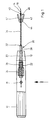
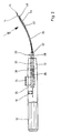
- the instrument shown has a rod-shaped handle 10, the cross section of which can be round or polygonal and which tapers conically towards its front end 12.
- the handle 10 is hollow. It contains a guide wire 14, which extends essentially on the longitudinal central axis of the handle 10 over its front half and emerges from an opening on the front face of the handle end 12. The guide wire 14 then follows an extension of the handle axis and is curved upward in the further course. The end of the guidewire 14 forms a hook 16.
- the guidewire 14 is so stiff that it maintains its shape in the long run. It is rigidly attached to the handle 10 with a clamping screw 18.
- a slide 20 is slidably mounted on the guide wire 14 in a telescopic arrangement, to which a slide part 26 accommodated in the handle 10 belongs.
- the handle 10 is provided with an elongated hole 22 extending in the longitudinal direction of the handle. It carries on its outside an actuating button 24, which is firmly connected through the elongated hole to the slide part 26 located inside the handle 10.
- the guide sleeve 28 goes to a shoulder 32 in a firmly attached seated, flexible tube 34 of smaller diameter, which is drawn onto the guide wire 14 and follows its curvature. At the end of the tube 34 there is a clamping mechanism firmly connected to it.
- the handle 10 contains a helical compression spring 36 lying around the guide sleeve 28, which is supported at one end at the front end of the slide part 26 and at the other end on a shoulder 38 located in the interior of the handle 10 in front of the guide bore 30.
- the spring 36 biases the slider 20 into the retracted position shown in FIGS. 1 and 2.
- the slide can be advanced by means of the actuating button 24 against the force of the spring 36 on the guide wire 14, as a result of which the tensioning mechanism and the hook 16 located at the end of the guide wire 14 perform a displacement movement relative to one another.
- the existing displacement play is predetermined by the length of the elongated hole 22, at the ends of which the actuating button 24 assumes stop positions. In the stop position, in which the slide 20 is pushed forward to the maximum and the compression spring 36 is tensioned, there is a locking possibility with a manually operated locking device, not shown.
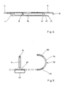
- FIGS. 3 to 5 The structure of the tensioning mechanism can be found in FIGS. 3 to 5.
- the central prong 40 of which essentially forms a straight extension of the tube 34, while the outer prongs 42 come to lie on both sides of the central prong 40 in a symmetrical arrangement and protrude from the apex 44 the fork where the tines 42, 44 meet, extend straight and obliquely outwards.
- the angle enclosed between the middle and the outer tines 40, 42 is approximately 15 °.
- the middle tine 40 is substantially flat and is provided with a downwardly angled ramp 46 at its end which projects beyond the outer tines 42.
- the guide wire 14 emerges from the crown 44 of the fork above the middle tine 40 and extends parallel and at a distance above the middle tine 40.
- the hook 16 at the end of the guide wire 14 is angled downward at 90 °. In the retracted stop position of the slide 20, the hook 16 comes to lie at some distance in front of the ramp 46 of the central tine 40 (representation with a solid line in FIG. 4). In the advanced stop position of the slide 20, the hook 16 is located between the outer tines 42 close to the apex 44 of the fork (dashed line in FIG. 4).
- the outer tines 42 of the fork are designed as jaws, between which an artificial lens can be clamped while elastically deforming its haptic part.
- the jaws have a U-profile with U-openings facing each other.
- the lower U-leg 48 of the U-profile lies in one plane with the middle prong 40, while the upper U-leg 50 extends somewhat above the guide wire 14.
- the U-back 52 of the profile is provided with a slot 54 running in the longitudinal direction of the jaw, which extends from the apex region 44 of the fork and extends right up to the ends of the jaws 42.
- the slots 54 are dimensioned so that the haptic part of an artificial lens fits through.
- the haptic part experiences a maximum of deformation at the unslit ends of the jaws, the distance of which corresponds approximately to the diameter of the optical part of the artificial lens.
- FIGS. 6 and 7 illustrate the handling of a disk lens 56 with the instrument according to the invention.
- the hook 16 is in a positioning opening 58 in the haptic part 60 of the disk lens 56 hooked.
- the slider 20 is advanced and the lens 56 is picked up with the middle prong 40 of the fork. This is facilitated by ramp 46.
- the lens 56 is clamped between the jaws 42 and the middle prong 40 of the fork serving as a back support and is elastically deformed at the jaw ends in such a way that the haptic part 60 is constricted essentially over the diameter of the lens 56.
- Smaller bellies 62, 64 of the haptic part 60 are formed in front of the jaw ends, and larger bellies behind the jaw ends, the latter 64 projecting outwards through the slots 54 of the jaws 42. As soon as the advanced stop position of the slide 20 according to FIG. 7 is reached, a locking takes place.
- the lens 56 can now be implanted with the instrument through a central round capsulorhexis into the lens capsule of an eye, the diameter of the capsulorhexis essentially corresponding to that of the optical part 66 of the lens 56.
- the lens 56 is inserted with the front smaller bellies 62 of the haptic part 60 forward through the capsulorhexis and, after the locking device has been released, is released by withdrawing the slide 20 from its clamping position, thereby returning to its original shape.
- An exact positioning of the lens 56 in the lens capsule takes place with the hook 16, which is finally released from the haptic part 60.
- the instrument has a hook plate 70 seated at the end of the guide wire with a flat rectangular plate body, the width of which corresponds approximately to that of the central prong 42. At the corners of the plate body 70 are four downwardly angled, backward curved hooks 72. In the retracted The stop position of the slide 20, the hook plate 70 comes to lie some distance in front of the ramp 46 of the middle tine 40. In the advanced stop position of the slide 20, the hook plate 70 is located between the outer tines 42 close to the apex 44 of the fork.
- a wider configuration of the middle prong 40 is preferred compared to the previously described instrument with a hook, since a chip lens to be implanted with an open round haptic requires a more extensive support when it is clamped.
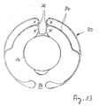
- FIG. 12 and 13 show chip lenses which are implanted with the instrument according to the invention.
- the lenses have a central optical lens body 74 and a haptic formed integrally therewith.
- a massive radial web 76 extends from the periphery of the lens body 74 at the shaping point of the haptic, while in the construction variant according to FIG. 13 two parallel thin webs 78 with approximately radial extension are provided.
- Haptic arms 80 extend from the webs 76, 78 in the opposite circumferential direction at a distance, around the lens body 74, and are not completely closed over the circumference, but leave a gap 82 between their ends.
- the arms 80 are constructed, at least in the region of the shaping point, from two radially spaced apart brackets 84 which extend parallel from the webs 76, 78.
- the hook plate 70 is dimensioned such that it engages over the webs 76, 78 and comes into engagement with the hook 72 at the attachment of the bracket 84.
- the engagement points are identified by a cross in FIGS. 12 and 13.
- the hook plate 70 on the haptic of the lens is in the retracted initial position of the slide 20 hooked.
- the slide 20 is advanced and the lens is picked up by the middle prong 40 of the fork.
- the lens is clamped between the jaws 42 and the middle prong 40 of the fork, which serves as a back support, and is elastically deformed at the jaw ends in such a way that the haptic arms fold and cross symmetrically.
- the lens is optimally reduced both in width and in length for implantation.
- the advanced stop position of the slide 20 is reached, it is locked.
Landscapes
- Health & Medical Sciences (AREA)
- Ophthalmology & Optometry (AREA)
- Cardiology (AREA)
- Oral & Maxillofacial Surgery (AREA)
- Transplantation (AREA)
- Engineering & Computer Science (AREA)
- Biomedical Technology (AREA)
- Heart & Thoracic Surgery (AREA)
- Vascular Medicine (AREA)
- Life Sciences & Earth Sciences (AREA)
- Animal Behavior & Ethology (AREA)
- General Health & Medical Sciences (AREA)
- Public Health (AREA)
- Veterinary Medicine (AREA)
- Prostheses (AREA)
Applications Claiming Priority (4)
| Application Number | Priority Date | Filing Date | Title |
|---|---|---|---|
| DE4000181 | 1990-01-05 | ||
| DE19904000181 DE4000181A1 (de) | 1990-01-05 | 1990-01-05 | Instrument zum implantieren einer kuenstlichen linse |
| DE4030004 | 1990-09-21 | ||
| DE19904030004 DE4030004A1 (de) | 1990-01-05 | 1990-09-21 | Instrument mit hakenplatte zum implantieren einer kuenstlichen linse |
Publications (1)
| Publication Number | Publication Date |
|---|---|
| EP0436232A1 true EP0436232A1 (fr) | 1991-07-10 |
Family
ID=25888840
Family Applications (1)
| Application Number | Title | Priority Date | Filing Date |
|---|---|---|---|
| EP90125806A Withdrawn EP0436232A1 (fr) | 1990-01-05 | 1990-12-29 | Applicateur pour l'implantation d'une lentille artificielle |
Country Status (2)
| Country | Link |
|---|---|
| EP (1) | EP0436232A1 (fr) |
| DE (1) | DE4030004A1 (fr) |
Cited By (14)
| Publication number | Priority date | Publication date | Assignee | Title |
|---|---|---|---|---|
| US5217464A (en) * | 1992-06-01 | 1993-06-08 | Henry H. McDonald | Three bar cross action lens implantation forceps |
| US5766182A (en) * | 1996-07-17 | 1998-06-16 | Henry H. McDonald | Multiple folding and handling of optical lens unit for placement in the eye |
| EP0937443A3 (fr) * | 1998-02-20 | 2000-11-22 | Acritec GmbH | Dispositif d'introduction pour lentille intra-oculaire |
| US8882781B2 (en) | 2002-03-15 | 2014-11-11 | Glaukos Corporation | Combined treatment for cataract and glaucoma treatment |
| US9173775B2 (en) | 2012-03-26 | 2015-11-03 | Glaukos Corporation | System for delivering multiple ocular implants |
| US9561131B2 (en) | 2001-08-28 | 2017-02-07 | Glaukos Corporation | Implant delivery system and methods thereof for treating ocular disorders |
| US9572963B2 (en) | 2001-04-07 | 2017-02-21 | Glaukos Corporation | Ocular disorder treatment methods and systems |
| US9592151B2 (en) | 2013-03-15 | 2017-03-14 | Glaukos Corporation | Systems and methods for delivering an ocular implant to the suprachoroidal space within an eye |
| US9597230B2 (en) | 2002-04-08 | 2017-03-21 | Glaukos Corporation | Devices and methods for glaucoma treatment |
| US9962290B2 (en) | 2006-11-10 | 2018-05-08 | Glaukos Corporation | Uveoscleral shunt and methods for implanting same |
| US9993368B2 (en) | 2000-04-14 | 2018-06-12 | Glaukos Corporation | System and method for treating an ocular disorder |
| USD846738S1 (en) | 2017-10-27 | 2019-04-23 | Glaukos Corporation | Implant delivery apparatus |
| US11376040B2 (en) | 2017-10-06 | 2022-07-05 | Glaukos Corporation | Systems and methods for delivering multiple ocular implants |
| US12419783B2 (en) | 2010-11-24 | 2025-09-23 | Glaukos Corporation | Drug eluting ocular implant |
Citations (2)
| Publication number | Priority date | Publication date | Assignee | Title |
|---|---|---|---|---|
| FR2604896A1 (fr) * | 1982-02-05 | 1988-04-15 | Mazzocco Thomas | Dispositif pour l'implantation dans l'oeil humain d'une lentille intraoculaire deformable |
| FR2631545A1 (fr) * | 1988-05-19 | 1989-11-24 | Biodomi | Applicateur pour l'implantation epicorneenne de lentilles souples |
-
1990
- 1990-09-21 DE DE19904030004 patent/DE4030004A1/de not_active Ceased
- 1990-12-29 EP EP90125806A patent/EP0436232A1/fr not_active Withdrawn
Patent Citations (2)
| Publication number | Priority date | Publication date | Assignee | Title |
|---|---|---|---|---|
| FR2604896A1 (fr) * | 1982-02-05 | 1988-04-15 | Mazzocco Thomas | Dispositif pour l'implantation dans l'oeil humain d'une lentille intraoculaire deformable |
| FR2631545A1 (fr) * | 1988-05-19 | 1989-11-24 | Biodomi | Applicateur pour l'implantation epicorneenne de lentilles souples |
Cited By (32)
| Publication number | Priority date | Publication date | Assignee | Title |
|---|---|---|---|---|
| US5217464A (en) * | 1992-06-01 | 1993-06-08 | Henry H. McDonald | Three bar cross action lens implantation forceps |
| US5766182A (en) * | 1996-07-17 | 1998-06-16 | Henry H. McDonald | Multiple folding and handling of optical lens unit for placement in the eye |
| EP0937443A3 (fr) * | 1998-02-20 | 2000-11-22 | Acritec GmbH | Dispositif d'introduction pour lentille intra-oculaire |
| US9993368B2 (en) | 2000-04-14 | 2018-06-12 | Glaukos Corporation | System and method for treating an ocular disorder |
| US10485702B2 (en) | 2000-04-14 | 2019-11-26 | Glaukos Corporation | System and method for treating an ocular disorder |
| US10828473B2 (en) | 2001-04-07 | 2020-11-10 | Glaukos Corporation | Ocular implant delivery system and methods thereof |
| US9572963B2 (en) | 2001-04-07 | 2017-02-21 | Glaukos Corporation | Ocular disorder treatment methods and systems |
| US9987472B2 (en) | 2001-04-07 | 2018-06-05 | Glaukos Corporation | Ocular implant delivery systems |
| US10285856B2 (en) | 2001-08-28 | 2019-05-14 | Glaukos Corporation | Implant delivery system and methods thereof for treating ocular disorders |
| US9561131B2 (en) | 2001-08-28 | 2017-02-07 | Glaukos Corporation | Implant delivery system and methods thereof for treating ocular disorders |
| US8882781B2 (en) | 2002-03-15 | 2014-11-11 | Glaukos Corporation | Combined treatment for cataract and glaucoma treatment |
| US9597230B2 (en) | 2002-04-08 | 2017-03-21 | Glaukos Corporation | Devices and methods for glaucoma treatment |
| US10485701B2 (en) | 2002-04-08 | 2019-11-26 | Glaukos Corporation | Devices and methods for glaucoma treatment |
| US9962290B2 (en) | 2006-11-10 | 2018-05-08 | Glaukos Corporation | Uveoscleral shunt and methods for implanting same |
| US10828195B2 (en) | 2006-11-10 | 2020-11-10 | Glaukos Corporation | Uveoscleral shunt and methods for implanting same |
| US12186237B2 (en) | 2006-11-10 | 2025-01-07 | Glaukos Corporation | Uveoscleral shunt and methods for implanting same |
| US12419783B2 (en) | 2010-11-24 | 2025-09-23 | Glaukos Corporation | Drug eluting ocular implant |
| US11197780B2 (en) | 2012-03-26 | 2021-12-14 | Glaukos Corporation | System and method for delivering multiple ocular implants |
| US11944573B2 (en) | 2012-03-26 | 2024-04-02 | Glaukos Corporation | System and method for delivering multiple ocular implants |
| US10271989B2 (en) | 2012-03-26 | 2019-04-30 | Glaukos Corporation | System and method for delivering multiple ocular implants |
| US9173775B2 (en) | 2012-03-26 | 2015-11-03 | Glaukos Corporation | System for delivering multiple ocular implants |
| US12343288B2 (en) | 2012-03-26 | 2025-07-01 | Glaukos Corporation | System and method for delivering multiple ocular implants |
| US9554940B2 (en) | 2012-03-26 | 2017-01-31 | Glaukos Corporation | System and method for delivering multiple ocular implants |
| US10188551B2 (en) | 2013-03-15 | 2019-01-29 | Glaukos Corporation | Systems and methods for delivering an ocular implant to the suprachoroidal space within an eye |
| US9592151B2 (en) | 2013-03-15 | 2017-03-14 | Glaukos Corporation | Systems and methods for delivering an ocular implant to the suprachoroidal space within an eye |
| US11523938B2 (en) | 2013-03-15 | 2022-12-13 | Glaukos Corporation | Systems and methods for delivering an ocular implant to the suprachoroidal space within an eye |
| US10285853B2 (en) | 2013-03-15 | 2019-05-14 | Glaukos Corporation | Systems and methods for delivering an ocular implant to the suprachoroidal space within an eye |
| US11376040B2 (en) | 2017-10-06 | 2022-07-05 | Glaukos Corporation | Systems and methods for delivering multiple ocular implants |
| US12414798B2 (en) | 2017-10-06 | 2025-09-16 | Glaukos Corporation | Systems and methods for delivering multiple ocular implants |
| USD938585S1 (en) | 2017-10-27 | 2021-12-14 | Glaukos Corporation | Implant delivery apparatus |
| USD901683S1 (en) | 2017-10-27 | 2020-11-10 | Glaukos Corporation | Implant delivery apparatus |
| USD846738S1 (en) | 2017-10-27 | 2019-04-23 | Glaukos Corporation | Implant delivery apparatus |
Also Published As
| Publication number | Publication date |
|---|---|
| DE4030004A1 (de) | 1992-03-26 |
Similar Documents
| Publication | Publication Date | Title |
|---|---|---|
| DE4108303C2 (de) | Verfahren und vorrichtung zum einbringen einer gummielastischen intraokularlinse in ein implantationswerkzeug | |
| DE69310345T2 (de) | Chirurgische instrumente | |
| DE69519587T2 (de) | Vorrichtung zum kontrollierten einsetzen einer intraokularlinse | |
| DE69431593T2 (de) | Apparat und verfahren für die vorbereitung des einsatzes einer intraokularen linse | |
| DE3348066C2 (fr) | ||
| DE19936666C2 (de) | Einstellbare intraokulare Linse und Verfahren zu ihrer Herstellung | |
| EP0436232A1 (fr) | Applicateur pour l'implantation d'une lentille artificielle | |
| DE3887143T2 (de) | Intraokulare linsenimplantation. | |
| EP0823247B1 (fr) | Crampon chirurgical pour chirurgie oculaire | |
| EP2001406B1 (fr) | Dispositif de fixation réversible d'un implant dans l'oeil | |
| DE60031850T2 (de) | Vorrichtung zur Chirurgie der Augenhornhaut | |
| EP2814406B1 (fr) | Dispositif permettant l'application d'une pince chirurgicale | |
| DE102005027215B4 (de) | Stapesprothese mit arretierbarem Piston | |
| DE4030005A1 (de) | Intraokularlinse | |
| DE3427830A1 (de) | Intraokularlinse | |
| EP3834776B1 (fr) | Lentille intraoculaire | |
| DE19925636B4 (de) | Intraokularlinse | |
| DE202008013320U1 (de) | Implantat zur Fixierung benachbarter Knochenplatten | |
| DE10105080B4 (de) | Verstellbare intraokulare Linse und zugehörige Verstellvorrichtung | |
| DE4000181A1 (de) | Instrument zum implantieren einer kuenstlichen linse | |
| DE102010055049A1 (de) | Nahtmaterial mit einer Nadelfixierung | |
| DE102020102685A1 (de) | Kapselspannring | |
| DE102020121049B4 (de) | Halter für ein mobiles Gerät | |
| EP3658002A1 (fr) | Élément de guidage pour dispositif endoscopique et dispositif endoscopique muni d'un tel élément de guidage | |
| DE2655042A1 (de) | Knotvorrichtung |
Legal Events
| Date | Code | Title | Description |
|---|---|---|---|
| PUAI | Public reference made under article 153(3) epc to a published international application that has entered the european phase |
Free format text: ORIGINAL CODE: 0009012 |
|
| AK | Designated contracting states |
Kind code of ref document: A1 Designated state(s): AT BE CH DE DK ES FR GB GR IT LI LU NL SE |
|
| 17P | Request for examination filed |
Effective date: 19920110 |
|
| STAA | Information on the status of an ep patent application or granted ep patent |
Free format text: STATUS: THE APPLICATION IS DEEMED TO BE WITHDRAWN |
|
| 18D | Application deemed to be withdrawn |
Effective date: 19930701 |