EP0436301A2 - Kristall-Polymermatrixverbundkomponenten - Google Patents
Kristall-Polymermatrixverbundkomponenten Download PDFInfo
- Publication number
- EP0436301A2 EP0436301A2 EP90312956A EP90312956A EP0436301A2 EP 0436301 A2 EP0436301 A2 EP 0436301A2 EP 90312956 A EP90312956 A EP 90312956A EP 90312956 A EP90312956 A EP 90312956A EP 0436301 A2 EP0436301 A2 EP 0436301A2
- Authority
- EP
- European Patent Office
- Prior art keywords
- guest
- compound
- host material
- crystals
- film
- Prior art date
- Legal status (The legal status is an assumption and is not a legal conclusion. Google has not performed a legal analysis and makes no representation as to the accuracy of the status listed.)
- Granted
Links
Images


Classifications
-
- G—PHYSICS
- G02—OPTICS
- G02F—OPTICAL DEVICES OR ARRANGEMENTS FOR THE CONTROL OF LIGHT BY MODIFICATION OF THE OPTICAL PROPERTIES OF THE MEDIA OF THE ELEMENTS INVOLVED THEREIN; NON-LINEAR OPTICS; FREQUENCY-CHANGING OF LIGHT; OPTICAL LOGIC ELEMENTS; OPTICAL ANALOGUE/DIGITAL CONVERTERS
- G02F1/00—Devices or arrangements for the control of the intensity, colour, phase, polarisation or direction of light arriving from an independent light source, e.g. switching, gating or modulating; Non-linear optics
- G02F1/35—Non-linear optics
- G02F1/355—Non-linear optics characterised by the materials used
- G02F1/361—Organic materials
- G02F1/3615—Organic materials containing polymers
-
- C—CHEMISTRY; METALLURGY
- C30—CRYSTAL GROWTH
- C30B—SINGLE-CRYSTAL GROWTH; UNIDIRECTIONAL SOLIDIFICATION OF EUTECTIC MATERIAL OR UNIDIRECTIONAL DEMIXING OF EUTECTOID MATERIAL; REFINING BY ZONE-MELTING OF MATERIAL; PRODUCTION OF A HOMOGENEOUS POLYCRYSTALLINE MATERIAL WITH DEFINED STRUCTURE; SINGLE CRYSTALS OR HOMOGENEOUS POLYCRYSTALLINE MATERIAL WITH DEFINED STRUCTURE; AFTER-TREATMENT OF SINGLE CRYSTALS OR A HOMOGENEOUS POLYCRYSTALLINE MATERIAL WITH DEFINED STRUCTURE; APPARATUS THEREFOR
- C30B13/00—Single-crystal growth by zone-melting; Refining by zone-melting
-
- C—CHEMISTRY; METALLURGY
- C30—CRYSTAL GROWTH
- C30B—SINGLE-CRYSTAL GROWTH; UNIDIRECTIONAL SOLIDIFICATION OF EUTECTIC MATERIAL OR UNIDIRECTIONAL DEMIXING OF EUTECTOID MATERIAL; REFINING BY ZONE-MELTING OF MATERIAL; PRODUCTION OF A HOMOGENEOUS POLYCRYSTALLINE MATERIAL WITH DEFINED STRUCTURE; SINGLE CRYSTALS OR HOMOGENEOUS POLYCRYSTALLINE MATERIAL WITH DEFINED STRUCTURE; AFTER-TREATMENT OF SINGLE CRYSTALS OR A HOMOGENEOUS POLYCRYSTALLINE MATERIAL WITH DEFINED STRUCTURE; APPARATUS THEREFOR
- C30B29/00—Single crystals or homogeneous polycrystalline material with defined structure characterised by the material or by their shape
- C30B29/54—Organic compounds
Definitions
- This invention relates to a method of producing polymer composites comprising polymeric matrices in which crystallites of organic and/or inorganic compounds are grown in situ.
- non-centrosymmetric crystals of some organic or inorganic compounds exhibit second-order, non-linear optical properties.
- non-centrosymmetric crystals is meant here and throughout the specification crystals with crystallographic space groups which lack a centre of inversion symmetry.
- Such second-order, non-linear optical properties include for instance second harmonic generation (hereafter "SHG”), which is the ability of certain crystals to emit radiation, e.g. light, of a frequency which is double the frequency of the beam incident on said crystal.
- SHG second harmonic generation
- the frequency-doubled light for instance has many uses, a common one being the pumping of dye lasers in the laboratory.
- non-centrosymmetric crystals capable of exhibiting such properties include potassium dihydrogenphosphate K[H2PO4] (hereafter “KDP”) and ammonium dihydrogenphosphate [NH4][H2PO4] (hereafter “ADP”).
- KDP potassium dihydrogenphosphate
- ADP ammonium dihydrogenphosphate
- These crystals can multiply the frequency of incident infra-red or visible light.
- such crystals are expensive to make, are fragile and have relatively low coefficients for SHG necessitating the use of high input beam powers.
- the present invention is a method of producing composites capable of SHG in which crystals of a Guest compound are aligned in a Host material, said method comprising passing a film of the composite in which Host molecules are in a random state through a temperature gradient melting zone (hereafter "TGMZ") comprising a hot region and a cold region having a sharp temperature gradient therebetween, the temperature (T2) of the hot region being above the melting point (and lower than its decomposition temperature) of the Guest compound but substantially within the elastic domain of the Host material, and the temperature (T1) of the cold region being substantially below the melting point of the Guest compound thereby enabling said Guest compound to crystallise, whereby the film is passed through said zone (from T2 to T1) at a speed which enables alignment of the Guest crystals in the Host material to form the composite.
- TGMZ temperature gradient melting zone
- the present invention is a method of producing composites capable of SHG in which the crystals of a Guest compound are aligned in a Host material, said method comprising passing a solution of the Guest compound and the Host material in a solvent placed on an appropriate substrate which is inert under the conditions used through a temperature gradient melting zone (hereafter "TGMZ") comprising a hot region and a cold region having a sharp temperature gradient therebetween, the temperature (T2) of the hot region being below the temperature at which the solvent boils, and the temperature (T1) of the cold region being substantially below T2 so as to enable the Guest compound to crystallise with the Host material, whereby the solution placed on the inert substrate is passed through the said zone from T1 to T2 at a speed which enables alignment of the Guest crystals in the Host material to form the composite.
- TGMZ temperature gradient melting zone
- organic compounds capable of forming non-centrosymmetric crystals include 3-nitroaniline (mNA) 3-methyl-4-nitropyridine-1-oxide, 2-methyl-4-nitroaniline (MNA), 2-dimethylamino-5-nitroacetanilide, urea and 2,4-dinitroaniline.
- mNA 3-nitroaniline
- MNA 2-methyl-4-nitroaniline
- 2-dimethylamino-5-nitroacetanilide 2-dimethylamino-5-nitroacetanilide
- urea 2,4-dinitroaniline
- inorganic compounds capable of forming non-centrosymmetric crystals include KDP, ADP, lithium niobate (V), benzylammonium dihydrogenphosphate (BAP), piperidinium dihydrogen phosphate (PDP), barium sodium niobate (V), and lithium iodate (V).
- ost is meant a polymer matrix which includes matrices of both homo- and co-polymers.
- the polymer matrix referred to herein is suitably in film form, preferably a thin film form.
- the films may have a thickness of up to 1 mm or more. It is also possible the material could be in other forms (e.g. rods).
- the polymer chosen for the matrix may be any polymer capable of being formed into a film.
- polymers that can be used include polystyrene (PS), polyethylene, polyacrylamide (PAA), polymethylmethacrylate (PMMA), poly(vinylcarbazole) (PVK), poly(vinylacetate) (PVA), polypropylene, ethylene-ethyl acrylate copolymers, polyvinyl chloride, polyvinylidene fluoride, polyvinyl pyrrolidone (PVP), and poly-oxyalkylene oxides such as polyethylene oxide (PEO).
- PS polystyrene
- PAA polyacrylamide
- PMMA polymethylmethacrylate
- PVK poly(vinylcarbazole)
- PVK poly(vinylacetate)
- PVA polypropylene
- ethylene-ethyl acrylate copolymers polyvinyl chloride, polyvinylidene fluoride, polyvinyl pyrroli
- the Guest compounds and Host materials are preferably such that when formed into a composite, said composites are transparent. It is possible to modify the refractive index matching of the composite by appropriate choice of the Guest compound and the Host material.
- the refractive indices of the Guest compound and the Host material may be the same or different. Dyes may be added to improve refractive index matching.
- the relative concentrations of the Guest compound and the Host material should be such that the Guest compound is capable of crystallisation in the Host material, preferably as needle like crystals, when subjected to a temperature gradient zone melting (hereafter "TGZM") technique, thereby forming a composite in which there are at least two solid phases and there is a discrete interface or borderline between the Guest crystals and the Host material.
- TTZM temperature gradient zone melting
- the composite suitably contains at least 10% w/w of the Guest compound in relation to the total weight of the Guest compound and the Host material, preferably at least 30% w/w and even more preferably at least 40% w/w of the Guest compound.
- this film may be formed by any one of the following methods. For instance:
- the extrusion temperature is preferably just above the melting point of the higher melting of the Host material and Guest compound.
- such crystals can be grown in situ in the Host polymer matrix by dissolving the Guest organic or inorganic compound to be crystallised and the matrix polymer in a common solvent and then casting the solution into the desired shape, e.g. a film, on a substrate, e.g glass, thereby allowing the compound to crystallise randomly in situ in the matrix upon gradual evaporation of the solvent.
- a substrate e.g. glass slide may be dipped into a common solution of the Host matrix polymer and the Guest compound in a solvent to be crystallised so as to form a coating of the solution on the substrate and then the solvent is allowed to evaporate from the coated substrate.
- the process may be repeated several times or the conditions modified to achieve the desired crystal density of film thickness.
- the crystals may be grown in situ in the Host polymer matrix by precipitation.
- a solution of a first compound and the matrix polymer is cast into a film on a substrate, the film is then dipped into a solution of a second compound.
- the desired crystals of the Guest compound may then be formed in the polymer matrix in situ either by a reaction between the first and second compounds or by the displacement of the first compound from the film by the second compound which may be the one of which crystals are to be formed.
- the specific technique chosen will depend upon several factors such as the nature of the polymer matrix, the crystals desired, the solubility of the compounds in any given solvent, the thickness of the polymer or the crystal density of the composite.
- the preformed film Once the preformed film has been produced, it is passed through the TGMZ in order to align the crystals of the Guest compound in the Host material.
- the film In passing the preformed film through the TGMZ, the film may be suitably subjected to either a stretching effect under an induced strain or a drawing effect, or a combination of both, in order to aid the alignment of the crystals of the Guest compound in the Host material. This may be achieved for instance by the use of a driven motor at a predetermined speed.
- the speed of drawing used is critical and will depend upon a number of variables including the temperature in the two regions of the TGMZ, the thickness of the film or the solution being passed through the zone, the concentration of the respective components in the preformed film or solution to be drawn, and the nature of the Guest compound or the Host material used.
- the TGZM/technique is suitably carried out as follows:
- the apparatus used is a TGZM apparatus and suitably consists of two aluminium blocks which form the hot and cold regions and they are suitably separated by a thin, e.g. at least 1 mm, thermally insulating layer to form a thermal junction.
- One block is heated to the desired temperature T2 and the other cooled to a temperature T1 in order to create a sharp temperature gradient.
- the hot block is suitably heated by any convenient means e.g. cartridge heaters inserted into the aluminium block and the cold block may be cooled e.g. by water or other coolant circulation.
- An enclosed channel may be provided on top of the aluminium blocks to allow the sample to be drawn across the thermal junction so formed.
- a sample holder can then be connected by means of a lead screw and a gear box to a motor which will enable the sample to be drawn from the hot to the cold region (block) of the apparatus at a predetermined rate.
- solutions of varying concentrations are prepared using toluene as solvent.
- Thin films e.g. 30-40 micrometers
- the preformed film is then covered with a second glass slide and placed in a sample holder of the TGZM device on the hot block.
- the hot region was maintained at 150°C (i.e. above the melting point of mNA) and the cold region was maintained at about 20°C.
- the sample in the hot region had softened, it is drawn slowly across the thermal junction at the optimised conditions of temperature differential, drawing speed etc, the Guest compound crystallises in a line within the Host material as it traverses the temperature gradient. In this case the crystals appear as fibre-like needles aligned parallel to the drawing axis. There is no measurable decay of SHG-activity with time (e.g. over a period of more than two years).
- the SHG-active composites are made from solution
- BAP was used as the Guest and PAA or PEO were used as the Host.
- the solution is suitably prepared in water.
- the solvent in this case, water
- the product is a colourless, transparent and non-scattering composite containing highly aligned microcrystals of BAP within the polymer Host.
- the necessary alignment may be achieved by dipping a microscope slide in a solution of the Guest and the Host. The slide is then placed in an enclosed channel on top of a metal block where one end of the metal block is heated, which generates a thermal gradient, forming a heated end and a cold end in a manner as described above.
- the thickness of the film in this case can be varied but is typically from 30-50 micrometers.
- the SHG activities of these films were tested using a Nd:YAG laser irradiating at 1064 nm.
- the molecular weight of the polymer Host is suitabiy from 2,000,000-5,000,000, typically 4,000,000, and the loading degree can be varied from 50-70%.
- the molecular weight may vary from 100,000-1,000,000, and the loading degree may be between 50 and 60%.
- composites may be formed from e.g. high melting polymers and high melting or low thermal stability Guest compounds.
- the optical quality of the composites so formed can be evaluated using optical microscopy, and the intensity and angular distribution of helium-neon laser scattering can also be determined by well known techniques.
- the efficiency of SHG was determined by irradiating the sample of the composite with 1064 nm IR radiation from Nd:YAG laser and observing the visible light at 532 nm; the intensity was measured by a photomultiplier.
- the present invention also covers the device used for producing these composites as an additional embodiment.
- the composites produced according to the present invention have high temporal stability.
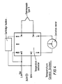
- the apparatus consists of two aluminium blocks which are connected by a 1 mm thermally insulating layer (Kaowool ceramic fibre insulation); the sample holder is connected to a motor, and temperature and speed control systems (see Fig. 1).
- the hot block was heated by heaters (two cartridge rods) which were inserted (hidden) within the block, and its temperature was controlled by a thermocouple sensor feedback system.
- the cold block was cooled by a liquid circulating system, in which cold water ran through channels inside the block. By controlling the amount of the circulating water (by controlling the circulating speed), the temperature of the cold block was controlled. This temperature was measured by inserting a thermocouple in a channel inside the cold block: the temperature step (T hot -T cold ) was measured within an accuracy of+/-2°C.
- the sample holder was connected to a screw, which was connected to a gearbox and a motor enabling it to be driven at various speeds.
- the speed control system was consisted of:
- the servo control module was connected to a 240 V power source.
- a potentiometer (5 K ohms) was connected to terminals 2 and 3 of the control module. The potentiometer was connected in order to produce various input voltages going into the servo motor via terminal 11 in the control module and therefore produce various drawing speeds. The relationship between the control potentiometer angular displacement and the motor rotation was established by prior calibration.
- a micro-switch was fixed at each end of the apparatus (as shown in Fig. 1) to turn the motor off once the sample reached either end.
- the servo motor was connected to terminal 10 in the control module through these microswitches.
- the apparatus was provided with a current limit resistor (R cl ) to prevent build up of current and thereby cause damage to the motor or the gearbox.
- R cl current limit resistor
- the speed control system was calibrated by measuring the distance, through which the sample was pulled in a certain time, using twelve digital settings (in the range 1 - 500) of the potentiometer. The speed was then calculated by applying:
- each digital number corresponds to a certain pulling speed, as shown in Fig. 3. (See tabulated format of Fig. 3 below). This arrangement enabled the sample to be pulled across the temperature step at any rate between 0.6 mm h ⁇ 1 and 102 mm h ⁇ 1. Calibration data on Temp. Gradient Speed Control
- the heating control system consisted of:
- a temperature controller was connected to a 240 V power source and to two cartridge heaters via terminal 8 to provide temperature range of 0-400°C.
- An external deviation meter (50-0-50 micro Amp) was connected via terminals 3 and 4 to the temperature controller in order to provide a more accurate reading of the temperature.
- a thermocouple sensor (type K) was connected to the temperature controller via terminals 5 and 7. The heaters were connected with the temperature controller in such a manner that if the temperature sensed by the sensor is below the set temperature, the output will be 'on', and if the temperature sensed is above the set temperature, the output will be 'off '.
- Solutions of different concentrations of the composite mNA/PMMA were prepared using toluene as a solvent (typically 15 g of mNA/PMMA mixture in 100 cm3 solvent). Thin films of the composite (30-40 micrometers) were cast on microscope glass slides and left to dry. Then each film was sandwiched between two glass slides and placed in the channel in the hot region of the aluminium block to melt, and then it was pulled at a certain speed towards the cold region. The hot block was kept at 150°C, which is higher than the melting point of the mNA (114°C) and lower than the decomposition point of the PMMA (160°C). The other block was cooled to about 20°C by circulating cold water in it.
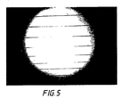
- the sample was kept in the channel in the hot region until it had melted or softened. Then the sample was drawn at a certain speed across the sharp temperature gradient from hot end to cold end. As the hot composite film reached the temperature step, it froze (crystallised) in a line across the film, and as it traversed across the gradient, the crystals grew as aligned fibres parallel to the axis of the film, as is shown in Fig. 5.
- Figure 5 shows a sample of mNA in PMMA (70 wt%) under the polarizing microscope: the crystals of mNA adopt a needle-like habit, which is strongly aligned along the drawing axis, i.e. along the direction of the thermal gradient. The technique resulted in excellent alignment of the organic nonlinear optical material in the rigid polymer matrix.
- Figure 6 gives an indication of the transparency obtained with the method.
- He-Ne laser scattering provided a quantitative measure of optical quality
- Figure 7 shows the scattering intensity of 632 nm light as a function of angle for both an aligned ( ) and a partially aligned (o) sample.
- the angular scattering pattern was narrow and symmetric about zero degrees (the forward direction).
- the peak represented transmissions at 632 nm of 88.7%.
- Higher peak transmissions were achieved using PVK as the polymer Host with a concomitantly narrower angular distribution (a result of improved refractive index matching between Guest and Host).
- SHG efficiency may be enhanced further by suitable choice of polymer Host, since refractive index matching may be achieved. This is demonstrated most clearly in Figure 9, where SHG efficiency was plotted as a function of refractive index mismatch (n) using several polymeric host species of differing refractive index.
- Poly(acrylamide) (1.5 g, Mw: 4,000,000-5,000,000) was dissolved in water (40 cm3) by stirring overnight (12 h) at 20°C. This produced an opaque solution. Benzylammonium dihydrogenphosphate (1.2 g) was then dissolved in the polymer solution.
- a film was then cast onto a microscope slide by dipping it into the mixture. Afterwards, one side of the slide was carefully wiped clean. The slide was then placed, clean side down, in the thermal-gradient apparatus.
- a thermal gradient was created across the apparatus by heating one end to 70°C, keeping the other end at 20°C.
- the slide was finally pulled along the apparatus from cold end to hot end at a speed of 84 mm/hour which produced a transparent, colourless, SHG-active composite.
- Polyethyleneoxide (1.2 g, Mw: 100,000) was dissolved in water (40 cm3) by stirring for 4 h at 20°C.
- Benzylammonium dihydrogenphosphate (1.8 g) was then dissolved in the aqueous polymer solution.
- the mixture was placed in a sonic bath for 10 min in order to remove any air bubbles.
- a film was then cast onto a microscope slide by dipping it into the mixture. Afterwards, one side of the slide was carefully wiped clean. The slide was then placed, clean side down, in the thermal-gradient apparatus.
- a thermal gradient was created across the apparatus by heating one end to 63°C, keeping the other end at 20°C.
- the slide was finally pulled across the gradient from cold end to hot end at 108 mm/hour to produce a transparent, colourless, SHG-active composite.
- Poly(vinylpyrrolidone) (PVP, 1.0 g, Mw: 40000) was dissolved in water (40 cm3) by stirring for 4 h at 20°C.
- Benzylammonium dihydrogenphosphate (BAP, 2.0 g) was then dissolved in the transparent aqueous polymer solution. The mixture was placed in a sonic bath for 10 mins in order to remove any air bubbles and to ensure that the Guest compound (benzylammonium dihydrogenphosphate) had dissolved completely.
- a film was then cast onto a microscope slide by dipping it into the mixture. Afterwards, one side of the slide was carefully wiped clean. The slide was then placed, clean side down, in the thermal-gradient apparatus.
- a thermal gradient was created across the apparatus by heating one end to 70°C, keeping the other end at 20°C.
- the slide was finally pulled across the gradient at 108 mm/hour to produce a transparent, colourless, SHG-active composite.
- Poly(acrylamide) (PAA, 1.5 g, Mw: 4000000-5000000) was dissolved in water (40 cm3) by stirring overnight (12 h) at 20°C. This produced an opaque solution.
- a film was then cast onto a microscope slide by dipping it into the mixture. Afterwards, one side of the slide was carefully wiped clean. The slide was then placed, clean side down, in the thermal-gradient apparatus.
- a thermal gradient was created across the apparatus by heating one end to 70°C, keeping the other end at 20°C.
- the slide was finally pulled along the apparatus at a speed of 84 mm/hour which produced a transparent, colourless, SHG-active composite.
- Polyethyleneoxide (PEO, 1.2 g, Mw: 100000) was dissolved in water (40 cm3) by stirring for 4 h at 20°C.
- Piperidinium dihydrogenphosphate (PDP, 1.8 g) was then dissolved in the aqueous polymer solution.
- the mixture was placed in a sonic bath for 10 mins in order toremove any air bubbles.
- a film was then cast onto a microscope slide by dipping it into the mixture. Afterwards, one side of the slide was carafully wiped clean. The slide was then placed, clean side down, in the thermal-gradient apparatus.
- a thermal gradient was created across the apparatus by heating one end to 63°C, keeping the other end at 20°C.
- the slide was finally pulled across the gradient at 108 mm/hour to produce a transparent, colourless, SHG-active composite.
- Poly(vinylpyrrolidone) (PVP, 1.0 g, Mw: 40000) was dissolved in water (40 cm3) by stirring for 6 h at 20°C.
- Piperidinium dihydrogenphosphate (PDP, 2.0 g) was then dissolved in the transparent aqueous polymer solution. The mixture was placed in a sonic bath for 10 min in order to remove any air bubbles and to ensure that the Guest compound (piperidinium dihydrogenphosphate) had dissolved completely.
- a film was then cast onto a microscope slide by dipping it into the mixture. Afterwards, one side of the slide was carefully wiped clean. The slide was then placed, clean side down, in the thermal-gradient apparatus.
- a thermal gradient was created across the apparatus by heating one end to 70°C, keeping the other end at 20°C.
- the slide was finally pulled across the gradient at 108 mm/hour to produce a transparent, colourless, SHG-active composite.
- Hot solutions of mNA/PMMA (15 g; 50%, 60% and 70% wt of mNA Guest in the total of Guest and Host) in toluene (100 ml) were prepared and films of these compositions were cast on to a microscope slide by dipping the slide into the respective hot solutions.
- the composite films so formed were then dried and thereafter another glass slide was placed on top of the dried composite film.
- a thermal gradient was created by heating one end of the TGMZ to 150°C and cooling the other to 20°C.
- the sample of the composite sandwiched between the two glass slides was placed on the hot end and then drawn towards the cold end. Best results in terms of alignment of crystals in the composite, transparency and SHG activity was observed at the following drawing speeds for the respective concentrations of the Guest and Host:
- the products were found to be highly aligned, highly transparent and the SHG activity (as determined by a Nd-YAG laser using KDP powder thickness of 200 micrometers as reference sample) in each case was > ⁇ 400 of the KDP reference sample.
- Example 8 The process of Example 8 was repeated to produce a 2-pyrrolidone-5-nitroacetanilide (PAN)/PMMA composite. In this case no alignment was observed upon examination under a polarised optical microscope because of the high melting temperature of PAN (220°C). Such high temperatures caused the polymer host to decompose.
- PAN 2-pyrrolidone-5-nitroacetanilide
- DAN/PMMA 2-dimethylamino-5-nitro acetanilide/PMMA (55%, 60% and 70% wt of DAN Guest in the total of Guest and Host) composites produced according to the procedure in Example 8 above was drawn through a temperature gradient of 180°C to 25°C (hot to cold). The composites were found to be highly aligned, transparent and highly SHG efficient. Best results were achieved at the following drawing speeds for the respective Guest concentrations.
- the composite was found to be highly aligned, highly transparent and highly SHG active.
- the composites were highly aligned, highly transparent and had high SHG activity.
- a range of BAP/PEO (60% wt of BAP Guest in the total of Guest and Host) composites using PEO of molecular weights 100000, 300000, 600000, 900000 and 4 ⁇ 106 were produced according to the procedure in Example 2 and a temperature gradient of 20-63°C (cold to hot). The drawing speed was 102 mm/hr.
- the resultant composites had good alignment, transparency and high SHG activity. It was observed that the lower the molecular weight of the Host the higher the degree of crystal alignment and the higher the transparency and SHG activity of the composite.
- a BAP/PVP (60% wt BAP Guest in the total of Guest and Host) Mol Wt 44000) composite was prepared according to the procedure in Example 2 and a temperature gradient of 20-70°C (cold to hot) using a drawing speed of 10 mm/hr.
- the resultant product had high alignment, high transparency and high SHG activity.
- a PDP/PVP (80% wt Guest PDP in the total of Guest and Host, Mol Wt 44000) composite was prepared according to the procedure in Example 2 and a temperature gradient of 20-70°C using a drawing speed of 102 mm/hr.
- the resultant composite had high transparency, was highly aligned and had high SHG activity.
- An mNA/PMMA (50% wt mNA Guest in the total of Guest and Host) composites were prepared according to the procedure in Example 2 except that the solvent used was n-butyl acetate and not water. The temperature gradient used was 20-50°C (cold to hot) and the drawing speed was 100 mm/hr. The resultant composite had high transparency, was highly aligned and had high SHG activity.
Landscapes
- Chemical & Material Sciences (AREA)
- Physics & Mathematics (AREA)
- Nonlinear Science (AREA)
- Metallurgy (AREA)
- Engineering & Computer Science (AREA)
- Crystallography & Structural Chemistry (AREA)
- Materials Engineering (AREA)
- Organic Chemistry (AREA)
- Optics & Photonics (AREA)
- General Physics & Mathematics (AREA)
- Manufacture Of Macromolecular Shaped Articles (AREA)
- Liquid Crystal Substances (AREA)
- Processes Of Treating Macromolecular Substances (AREA)
- Compositions Of Macromolecular Compounds (AREA)
- Other Resins Obtained By Reactions Not Involving Carbon-To-Carbon Unsaturated Bonds (AREA)
- Treatments Of Macromolecular Shaped Articles (AREA)
- Compounds Of Unknown Constitution (AREA)
Applications Claiming Priority (4)
| Application Number | Priority Date | Filing Date | Title |
|---|---|---|---|
| GB8927085 | 1989-11-30 | ||
| GB898927085A GB8927085D0 (en) | 1989-11-30 | 1989-11-30 | Polymer composites |
| GB909008839A GB9008839D0 (en) | 1990-04-19 | 1990-04-19 | Polymer composites |
| GB9008839 | 1990-04-19 |
Publications (3)
| Publication Number | Publication Date |
|---|---|
| EP0436301A2 true EP0436301A2 (de) | 1991-07-10 |
| EP0436301A3 EP0436301A3 (en) | 1992-11-25 |
| EP0436301B1 EP0436301B1 (de) | 1995-03-15 |
Family
ID=26296281
Family Applications (1)
| Application Number | Title | Priority Date | Filing Date |
|---|---|---|---|
| EP90312956A Expired - Lifetime EP0436301B1 (de) | 1989-11-30 | 1990-11-28 | Kristall-Polymermatrixverbundkomponenten |
Country Status (7)
| Country | Link |
|---|---|
| US (1) | US5167888A (de) |
| EP (1) | EP0436301B1 (de) |
| JP (1) | JPH03274533A (de) |
| AT (1) | ATE119952T1 (de) |
| CA (1) | CA2031148A1 (de) |
| DE (1) | DE69017873T2 (de) |
| ES (1) | ES2071047T3 (de) |
Cited By (1)
| Publication number | Priority date | Publication date | Assignee | Title |
|---|---|---|---|---|
| WO2002008500A3 (en) * | 2000-07-25 | 2002-05-30 | Univ Texas | In situ regrowth and purification of crystalline thin films |
Family Cites Families (13)
| Publication number | Priority date | Publication date | Assignee | Title |
|---|---|---|---|---|
| US3360406A (en) * | 1965-12-03 | 1967-12-26 | Bell Telephone Labor Inc | Temperature gradient zone melting and growing of semiconductor material |
| GB2055855A (en) * | 1979-08-07 | 1981-03-11 | Ici Ltd | Heat-treating polyolefin films |
| GB2090465B (en) * | 1980-12-29 | 1985-11-13 | Gen Electric | Production of p-n junctions by the electromigration method |
| US4407879A (en) * | 1981-08-07 | 1983-10-04 | Northern Petrochemical Company | Method of producing a textured film |
| JPS5956446A (ja) * | 1982-09-24 | 1984-03-31 | Nippon Oil Co Ltd | ポリビニルアルコ−ル凍結ゲルの柔軟性低下法 |
| US4692285A (en) * | 1985-07-01 | 1987-09-08 | Pennwalt Corporation | Process of preparing nonfibrous, piezoelectric polymer sheet of improved activity |
| JPH0686594B2 (ja) * | 1985-09-20 | 1994-11-02 | 日本石油株式会社 | モノドメイン化されたコレステリツク液晶性ポリエステルフイルムまたはシ−トの製造方法 |
| US4806579A (en) * | 1986-01-30 | 1989-02-21 | The British Petroleum Co. P.L.C. | Polymer composites |
| FR2596692B1 (fr) * | 1986-04-04 | 1988-09-09 | Atochem | Tubes en matiere plastique semi-cristalline extrudes presentant une resistance au choc a froid et a la traction amelioree par un traitement thermique et leur procede de fabrication |
| JPS62242517A (ja) * | 1986-04-14 | 1987-10-23 | Kureha Chem Ind Co Ltd | ポリパラフェニレンスルフィド2軸延伸フィルム及びその製造方法 |
| EP0284229B1 (de) * | 1987-03-06 | 1993-07-21 | Canon Kabushiki Kaisha | Nichtlineares optisches Material und Verfahren zu dessen Orientierung |
| GB2205767B (en) * | 1987-06-18 | 1991-04-17 | Gen Electric Plc | Organic-optical waveguides. |
| JPH02199432A (ja) * | 1989-01-30 | 1990-08-07 | Nippon Telegr & Teleph Corp <Ntt> | 非線形光学素子およびその製造方法 |
-
1990
- 1990-11-26 US US07/617,565 patent/US5167888A/en not_active Expired - Fee Related
- 1990-11-28 ES ES90312956T patent/ES2071047T3/es not_active Expired - Lifetime
- 1990-11-28 AT AT90312956T patent/ATE119952T1/de not_active IP Right Cessation
- 1990-11-28 EP EP90312956A patent/EP0436301B1/de not_active Expired - Lifetime
- 1990-11-28 DE DE69017873T patent/DE69017873T2/de not_active Expired - Fee Related
- 1990-11-29 CA CA002031148A patent/CA2031148A1/en not_active Abandoned
- 1990-11-29 JP JP2336962A patent/JPH03274533A/ja active Pending
Cited By (2)
| Publication number | Priority date | Publication date | Assignee | Title |
|---|---|---|---|---|
| WO2002008500A3 (en) * | 2000-07-25 | 2002-05-30 | Univ Texas | In situ regrowth and purification of crystalline thin films |
| US6840999B2 (en) | 2000-07-25 | 2005-01-11 | Board Of Regents The University Of Texas System | In situ regrowth and purification of crystalline thin films |
Also Published As
| Publication number | Publication date |
|---|---|
| JPH03274533A (ja) | 1991-12-05 |
| EP0436301B1 (de) | 1995-03-15 |
| CA2031148A1 (en) | 1991-05-31 |
| EP0436301A3 (en) | 1992-11-25 |
| DE69017873T2 (de) | 1995-07-20 |
| ATE119952T1 (de) | 1995-04-15 |
| ES2071047T3 (es) | 1995-06-16 |
| DE69017873D1 (de) | 1995-04-20 |
| US5167888A (en) | 1992-12-01 |
Similar Documents
| Publication | Publication Date | Title |
|---|---|---|
| CA1308843C (en) | Polymer composites | |
| DE3789115T2 (de) | Verfahren zur herstellung eines optischen wellenleiters und erzeugnis. | |
| Miedzinski et al. | Z-scan measurements of the third-order optical nonlinearities and linear optical properties of 70TeO2-5MxOy-10P2O5-10ZnO-5PbF2 glasses doped with Er3+ ions modified by transition metals | |
| Si et al. | Optical poling and its application in optical storage of a polyimide film with high glass transition temperature | |
| Mohajerani et al. | Polarisation sensitive optical phase conjugation in novel polymer films | |
| US5167888A (en) | Polymer composites | |
| JPH09512354A (ja) | 非線形結晶及びそれらの利用 | |
| Liu et al. | Flux growth of nonlinear optical crystal K3B6O10Br with high optical quality and its electro-optical property | |
| KR100499240B1 (ko) | 비선형 광학결정 및 그를 이용한 파장변환방법 | |
| US6608205B1 (en) | Organic crystalline films for optical applications and related methods of fabrication | |
| Anneser et al. | Photoinduced generation of noncentrosymmetric structures in glassy liquid crystalline polysiloxanes for second harmonic generation | |
| US4985178A (en) | Nonlinear optical device from 3-methyl-4-methoxy-4'-nitrostilbene | |
| D'yakov et al. | Lithium sodium carbonate: A new nonlinear-optics crystal | |
| Umegaki et al. | Crystal Growth Of Organic Material And Optical Second-Harmonic Generation In Optical Fiber | |
| Roth | Stoichiometry and domain structure of KTP-type nonlinear optical crystals | |
| Komatsu et al. | Laser-induced line patterning of nonlinear optical crystals in glass | |
| Xu et al. | Optical poling in a crosslinkable polymer system. | |
| DE69121046T2 (de) | Organischer nichtlinear-optischer kristall mit schichtstruktur und seine herstellung | |
| Watanabe et al. | Effect of crystallization process on the second harmonic generation of poly (oxyethylene)/p-nitroaniline systems | |
| Sukumar et al. | Growth, dielectric and nonlinear optical properties of Li3Cs2B5O10 single crystals | |
| WO1991003458A1 (en) | Nonlinear optical device from 3-methyl-4-methoxy-4'-nitrostilbene | |
| Chandrasekaran et al. | Growth, spectral, optical, thermal and third harmonic generation studies of strontium dicitrato borate heptahydrate nonlinear optical single crystals | |
| Ohmi et al. | Nonlinear optical properties of a fiber with an organic core crystal grown from solution | |
| DE4317095A1 (de) | Verfahren zur Polung und Orientierung von organischen Materialien, die nichtlinear optische Chromophore enthalten, und deren Verwendung | |
| Nicholls et al. | Synthesis, growth and assessment of mixed niobate–borate (XYB2O6) compounds |
Legal Events
| Date | Code | Title | Description |
|---|---|---|---|
| PUAI | Public reference made under article 153(3) epc to a published international application that has entered the european phase |
Free format text: ORIGINAL CODE: 0009012 |
|
| AK | Designated contracting states |
Kind code of ref document: A2 Designated state(s): AT BE CH DE ES FR GB IT LI NL |
|
| PUAL | Search report despatched |
Free format text: ORIGINAL CODE: 0009013 |
|
| AK | Designated contracting states |
Kind code of ref document: A3 Designated state(s): AT BE CH DE ES FR GB IT LI NL |
|
| RAP1 | Party data changed (applicant data changed or rights of an application transferred) |
Owner name: THE BRITISH PETROLEUM COMPANY P.L.C. |
|
| 17P | Request for examination filed |
Effective date: 19930510 |
|
| 17Q | First examination report despatched |
Effective date: 19930910 |
|
| RAP1 | Party data changed (applicant data changed or rights of an application transferred) |
Owner name: BRITISH TECHNOLOGY GROUP LIMITED |
|
| GRAA | (expected) grant |
Free format text: ORIGINAL CODE: 0009210 |
|
| AK | Designated contracting states |
Kind code of ref document: B1 Designated state(s): AT BE CH DE ES FR GB IT LI NL |
|
| REF | Corresponds to: |
Ref document number: 119952 Country of ref document: AT Date of ref document: 19950415 Kind code of ref document: T |
|
| ITF | It: translation for a ep patent filed | ||
| REF | Corresponds to: |
Ref document number: 69017873 Country of ref document: DE Date of ref document: 19950420 |
|
| ET | Fr: translation filed | ||
| REG | Reference to a national code |
Ref country code: ES Ref legal event code: FG2A Ref document number: 2071047 Country of ref document: ES Kind code of ref document: T3 |
|
| PLBE | No opposition filed within time limit |
Free format text: ORIGINAL CODE: 0009261 |
|
| STAA | Information on the status of an ep patent application or granted ep patent |
Free format text: STATUS: NO OPPOSITION FILED WITHIN TIME LIMIT |
|
| 26N | No opposition filed | ||
| PGFP | Annual fee paid to national office [announced via postgrant information from national office to epo] |
Ref country code: GB Payment date: 19971017 Year of fee payment: 8 |
|
| PGFP | Annual fee paid to national office [announced via postgrant information from national office to epo] |
Ref country code: FR Payment date: 19971020 Year of fee payment: 8 |
|
| PGFP | Annual fee paid to national office [announced via postgrant information from national office to epo] |
Ref country code: DE Payment date: 19971021 Year of fee payment: 8 |
|
| PGFP | Annual fee paid to national office [announced via postgrant information from national office to epo] |
Ref country code: NL Payment date: 19971023 Year of fee payment: 8 |
|
| PGFP | Annual fee paid to national office [announced via postgrant information from national office to epo] |
Ref country code: AT Payment date: 19971103 Year of fee payment: 8 |
|
| PGFP | Annual fee paid to national office [announced via postgrant information from national office to epo] |
Ref country code: ES Payment date: 19971104 Year of fee payment: 8 |
|
| PGFP | Annual fee paid to national office [announced via postgrant information from national office to epo] |
Ref country code: BE Payment date: 19971203 Year of fee payment: 8 |
|
| PGFP | Annual fee paid to national office [announced via postgrant information from national office to epo] |
Ref country code: CH Payment date: 19980223 Year of fee payment: 8 |
|
| PG25 | Lapsed in a contracting state [announced via postgrant information from national office to epo] |
Ref country code: GB Free format text: LAPSE BECAUSE OF NON-PAYMENT OF DUE FEES Effective date: 19981128 Ref country code: AT Free format text: LAPSE BECAUSE OF NON-PAYMENT OF DUE FEES Effective date: 19981128 |
|
| PG25 | Lapsed in a contracting state [announced via postgrant information from national office to epo] |
Ref country code: ES Free format text: LAPSE BECAUSE OF NON-PAYMENT OF DUE FEES Effective date: 19981129 |
|
| PG25 | Lapsed in a contracting state [announced via postgrant information from national office to epo] |
Ref country code: LI Free format text: LAPSE BECAUSE OF NON-PAYMENT OF DUE FEES Effective date: 19981130 Ref country code: CH Free format text: LAPSE BECAUSE OF NON-PAYMENT OF DUE FEES Effective date: 19981130 Ref country code: BE Free format text: LAPSE BECAUSE OF NON-PAYMENT OF DUE FEES Effective date: 19981130 |
|
| BERE | Be: lapsed |
Owner name: BRITISH TECHNOLOGY GROUP LTD Effective date: 19981130 |
|
| PG25 | Lapsed in a contracting state [announced via postgrant information from national office to epo] |
Ref country code: NL Free format text: LAPSE BECAUSE OF NON-PAYMENT OF DUE FEES Effective date: 19990601 |
|
| REG | Reference to a national code |
Ref country code: CH Ref legal event code: PL |
|
| GBPC | Gb: european patent ceased through non-payment of renewal fee |
Effective date: 19981128 |
|
| PG25 | Lapsed in a contracting state [announced via postgrant information from national office to epo] |
Ref country code: FR Free format text: LAPSE BECAUSE OF NON-PAYMENT OF DUE FEES Effective date: 19990730 |
|
| NLV4 | Nl: lapsed or anulled due to non-payment of the annual fee |
Effective date: 19990601 |
|
| REG | Reference to a national code |
Ref country code: FR Ref legal event code: ST |
|
| PG25 | Lapsed in a contracting state [announced via postgrant information from national office to epo] |
Ref country code: DE Free format text: LAPSE BECAUSE OF NON-PAYMENT OF DUE FEES Effective date: 19990901 |
|
| REG | Reference to a national code |
Ref country code: ES Ref legal event code: FD2A Effective date: 19991214 |
|
| PG25 | Lapsed in a contracting state [announced via postgrant information from national office to epo] |
Ref country code: IT Free format text: LAPSE BECAUSE OF NON-PAYMENT OF DUE FEES;WARNING: LAPSES OF ITALIAN PATENTS WITH EFFECTIVE DATE BEFORE 2007 MAY HAVE OCCURRED AT ANY TIME BEFORE 2007. THE CORRECT EFFECTIVE DATE MAY BE DIFFERENT FROM THE ONE RECORDED. Effective date: 20051128 |