EP0436330A1 - Dual flow single cell rotary compressor - Google Patents
Dual flow single cell rotary compressor Download PDFInfo
- Publication number
- EP0436330A1 EP0436330A1 EP90313624A EP90313624A EP0436330A1 EP 0436330 A1 EP0436330 A1 EP 0436330A1 EP 90313624 A EP90313624 A EP 90313624A EP 90313624 A EP90313624 A EP 90313624A EP 0436330 A1 EP0436330 A1 EP 0436330A1
- Authority
- EP
- European Patent Office
- Prior art keywords
- journal bearing
- situated
- inlet port
- defining
- cylindrical chamber
- Prior art date
- Legal status (The legal status is an assumption and is not a legal conclusion. Google has not performed a legal analysis and makes no representation as to the accuracy of the status listed.)
- Withdrawn
Links
- 230000009977 dual effect Effects 0.000 title description 4
- 238000005096 rolling process Methods 0.000 abstract description 3
- 239000003507 refrigerant Substances 0.000 description 4
- 238000005086 pumping Methods 0.000 description 3
- 229910001018 Cast iron Inorganic materials 0.000 description 1
- 235000014676 Phragmites communis Nutrition 0.000 description 1
- 229910000831 Steel Inorganic materials 0.000 description 1
- 230000006835 compression Effects 0.000 description 1
- 238000007906 compression Methods 0.000 description 1
- 239000002184 metal Substances 0.000 description 1
- 229910052751 metal Inorganic materials 0.000 description 1
- 239000010959 steel Substances 0.000 description 1
- 238000010408 sweeping Methods 0.000 description 1
Images

Classifications
-
- F—MECHANICAL ENGINEERING; LIGHTING; HEATING; WEAPONS; BLASTING
- F04—POSITIVE - DISPLACEMENT MACHINES FOR LIQUIDS; PUMPS FOR LIQUIDS OR ELASTIC FLUIDS
- F04C—ROTARY-PISTON, OR OSCILLATING-PISTON, POSITIVE-DISPLACEMENT MACHINES FOR LIQUIDS; ROTARY-PISTON, OR OSCILLATING-PISTON, POSITIVE-DISPLACEMENT PUMPS
- F04C29/00—Component parts, details or accessories of pumps or pumping installations, not provided for in groups F04C18/00 - F04C28/00
- F04C29/12—Arrangements for admission or discharge of the working fluid, e.g. constructional features of the inlet or outlet
- F04C29/124—Arrangements for admission or discharge of the working fluid, e.g. constructional features of the inlet or outlet with inlet and outlet valves specially adapted for rotary or oscillating piston pumps
- F04C29/126—Arrangements for admission or discharge of the working fluid, e.g. constructional features of the inlet or outlet with inlet and outlet valves specially adapted for rotary or oscillating piston pumps of the non-return type
-
- F—MECHANICAL ENGINEERING; LIGHTING; HEATING; WEAPONS; BLASTING
- F04—POSITIVE - DISPLACEMENT MACHINES FOR LIQUIDS; PUMPS FOR LIQUIDS OR ELASTIC FLUIDS
- F04C—ROTARY-PISTON, OR OSCILLATING-PISTON, POSITIVE-DISPLACEMENT MACHINES FOR LIQUIDS; ROTARY-PISTON, OR OSCILLATING-PISTON, POSITIVE-DISPLACEMENT PUMPS
- F04C18/00—Rotary-piston pumps specially adapted for elastic fluids
- F04C18/30—Rotary-piston pumps specially adapted for elastic fluids having the characteristics covered by two or more of groups F04C18/02, F04C18/08, F04C18/22, F04C18/24, F04C18/48, or having the characteristics covered by one of these groups together with some other type of movement between co-operating members
- F04C18/34—Rotary-piston pumps specially adapted for elastic fluids having the characteristics covered by two or more of groups F04C18/02, F04C18/08, F04C18/22, F04C18/24, F04C18/48, or having the characteristics covered by one of these groups together with some other type of movement between co-operating members having the movement defined in group F04C18/08 or F04C18/22 and relative reciprocation between the co-operating members
- F04C18/356—Rotary-piston pumps specially adapted for elastic fluids having the characteristics covered by two or more of groups F04C18/02, F04C18/08, F04C18/22, F04C18/24, F04C18/48, or having the characteristics covered by one of these groups together with some other type of movement between co-operating members having the movement defined in group F04C18/08 or F04C18/22 and relative reciprocation between the co-operating members with vanes reciprocating with respect to the outer member
- F04C18/3562—Rotary-piston pumps specially adapted for elastic fluids having the characteristics covered by two or more of groups F04C18/02, F04C18/08, F04C18/22, F04C18/24, F04C18/48, or having the characteristics covered by one of these groups together with some other type of movement between co-operating members having the movement defined in group F04C18/08 or F04C18/22 and relative reciprocation between the co-operating members with vanes reciprocating with respect to the outer member the inner and outer member being in contact along one line or continuous surfaces substantially parallel to the axis of rotation
- F04C18/3564—Rotary-piston pumps specially adapted for elastic fluids having the characteristics covered by two or more of groups F04C18/02, F04C18/08, F04C18/22, F04C18/24, F04C18/48, or having the characteristics covered by one of these groups together with some other type of movement between co-operating members having the movement defined in group F04C18/08 or F04C18/22 and relative reciprocation between the co-operating members with vanes reciprocating with respect to the outer member the inner and outer member being in contact along one line or continuous surfaces substantially parallel to the axis of rotation the surfaces of the inner and outer member, forming the working space, being surfaces of revolution
Definitions
- the present invention relates to a two stage compressor and more specifically to a rotary compressor for pumping two separate refrigerant flows to a single higher pressure.
- a rotary compressor having a frame defining a cylindrical aperture and a vane slot extending radially outwardly from the cylindrical aperture.
- the frame also defines a first inlet port extending radially outwardly from said cylindrical aperture through the frame on one side of the vane slot.
- a vane is slidably mounted in the vane slot.
- Two journal bearing plates each define a journal bearing extending axially therethrough and are situated on either side of the cylindrical aperture defining a cylindrical chamber.
- the first journal bearing plate defines a second inlet port extending axially inwardly through the journal bearing plate.
- the second inlet port is situated on the other side of the vane from the first inlet port.
- the second journal bearing plate further defines an outlet port extending axially through the second journal plate.
- the outlet port is situated opposite the second inlet port.
- a first check valve is situated in the second inlet port for permitting flow only axially inwardly.
- a second check valve is situated in the outlet port for permitting flow only from the cylindrical chamber.
- a shaft extends through the cylindrical chamber and is rotatably mounted in the journal bearings. The portion of the shaft situated in the cylindrical chamber has an eccentrically extending circular lobe.
- a piston surrounds the circular lobe and contacts a portion of the cylindrical chamber periphery and both journal bearing plates.
- a dual flow single cell rotary compressor 5 which is typically situated in a hermetically sealed housing (not shown).
- the rotary compressor has a frame 7 defining a cylindrical aperture 11 and a vane slot 13 extending radially outwardly from the cylindrical aperture.
- a hollow shaft 15 is situated concentrically in the cylindrical aperture.
- the shaft is rotatably supported by a journal bearing 17 located in a journal bearing plate 21 on one side and a journal bearing plate 23 having a journal bearing 25 on the other.
- the frame 7, the journal bearing plate 21 and the journal bearing plate 23 together define a cylindrical chamber.
- the portion of the shaft situated in the cylindrical chamber has an eccentrically positioned circular lobe 27 extending therefrom.
- the circular lobe is surrounded by a close fitting annular member called a rolling piston 31.
- the rolling piston is in contact with the circular lobe and a portion of the cylindrical wall of the chamber.
- the piston is free to rotate about the circular lobe.
- a vane 33 is slidably mounted in the vane slot 13 in the frame biased towards the piston contacting the piston by a spring 35.
- An electric motor rotor 37 is mounted on the portion of the shaft extending through the journal bearing plate 21.
- the portion of the shaft extending through the journal bearing plate 23 is closed off by a cap 41 which has a friction fit.
- the cylindrical chamber is in flow communication with a first inlet port 43 extending radially outwardly from the cylindrical chamber through the frame 7 situated adjacent to one side of the vane 33.
- a check valve is not needed in this port.
- a second inlet port 52 extends axially inwardly through the cover plate 23.
- a check valve 53 is situated in this port and can comprise a ball check valve which permits flow into the cylindrical chamber but not out.
- the second inlet port is situated on the opposite side of the vane 33 from the first inlet port 43.
- An outlet port 55 extends from a position opposite from the second inlet port 52 axially through the journal bearing plate 21 through a check valve.
- a reed check valve 57 is shown in the Figures comprising a flexible piece of metal 59 secured to the plate. A portion of the flexible piece 59 covers the outlet port permitting flow only from the cylindrical chamber.
- the exterior portion of the journal bearing plate 21 is covered by a close fitting housing 61 which serves a muffler.
- the vane 33 divides the volume surrounding the piston 31 into a high pressure and a low pressure region.
- the piston contacts the cylindrical chamber walls in a sweeping circular motion which moves in the same direction and at the same rate as the shaft 17 rotates.
- the operation of the compressor is shown in the sequence of schematic Figures 3, 4 and 5 showing different positions of the piston.
- the pressures used in describing the operation are those needed to operate the cycle described in US Patent 4910972, the description of which is incorporated herein by reference. Other pressures of course could be supplied and achieved by the rotary compressor.
- the shaft rotates in the clockwise direction as viewed.
- the first inlet port 43 is covered by the piston 31 and the second inlet port is uncovered admitting the higher pressure gas (39 psi).
- the higher pressure gas fills the chamber mixing with the lower pressure gas.
- the shaft 17 is driven by an electric motor the stator of which is not shown.
- the spring 35 holds the vane 33 against the piston 31 during initial operation. Once the cycle starts the high pressure gas is discharged into the hermetically sealed housing (not shown) surrounding the frame 7. The high pressure gas pushes the vane against the piston. Tubes connected to the two inlet ports pass through the hermetically sealed housing the outlet tube is in flow communication with the housing.
- the frame, journal bearing plate 23 and journal plate can be fabricated from cast iron.
- the piston and vane can be fabricated from steel.
Landscapes
- Engineering & Computer Science (AREA)
- Mechanical Engineering (AREA)
- General Engineering & Computer Science (AREA)
- Applications Or Details Of Rotary Compressors (AREA)
Abstract
A rotary compressor having a frame defining a cylindrical aperture (11) and a vane slot (33) extending radially outwardly from the cylindrical aperture is provided. The frame also defines a first inlet port (43) extending radially outwardly from said cylindrical aperture through the frame on one side of the vane slot. A vane (33) is slidably mounted in the vane slot. Two journal bearing plates (21 (not in Fig.1) and 23), each defining a journal bearing extending axially therethrough, are situated on either side of the cylindrical aperture defining a cylindrical chamber. The first journal bearing plate (23) defines a second inlet port extending axially inwardly through the first journal bearing plate. The second inlet port is situated on the other side of the vane from the first inlet port. The second journal bearing plate (21) further defines an outlet port (55) extending axially through the second journal plate. The outlet port is situated opposite the second inlet port. A first check valve is situated in the second inlet port for permitting flow only axially inwardly. A second check valve is situated in the outlet port for permitting flow only from the cylindrical chamber. A shaft (15) extends through the cylindrical chamber and is rotatably mounted in the journal bearings. The portion of the shaft situated in the cylindrical chamber has an eccentrically extending circular lobe (27). A rolling piston (31) surrounds the circular lobe and contacts a portion of the cylindrical chamber periphery and the cover and both journal bearing plates.
Description
- This application is related to our co-filed European Application No. (RD-19744) having the same title.
- The present invention relates to a two stage compressor and more specifically to a rotary compressor for pumping two separate refrigerant flows to a single higher pressure.
- Some refrigerant cycles such as that disclosed in US Patent No. 4910972 entitled "Refrigerator Systems With Dual Evaporators for Household Refrigerators" require two separate compressors or a single two-stage compressor.
- It is an object of the present invention to provide a rotary compressor capable of pumping two separate refrigerant flows at different pressures through a single cavity to a single higher pressure.
- In one aspect of the present invention a rotary compressor having a frame defining a cylindrical aperture and a vane slot extending radially outwardly from the cylindrical aperture is provided. The frame also defines a first inlet port extending radially outwardly from said cylindrical aperture through the frame on one side of the vane slot. A vane is slidably mounted in the vane slot. Two journal bearing plates each define a journal bearing extending axially therethrough and are situated on either side of the cylindrical aperture defining a cylindrical chamber. The first journal bearing plate defines a second inlet port extending axially inwardly through the journal bearing plate. The second inlet port is situated on the other side of the vane from the first inlet port. The second journal bearing plate further defines an outlet port extending axially through the second journal plate. The outlet port is situated opposite the second inlet port. A first check valve is situated in the second inlet port for permitting flow only axially inwardly. A second check valve is situated in the outlet port for permitting flow only from the cylindrical chamber. A shaft extends through the cylindrical chamber and is rotatably mounted in the journal bearings. The portion of the shaft situated in the cylindrical chamber has an eccentrically extending circular lobe. A piston surrounds the circular lobe and contacts a portion of the cylindrical chamber periphery and both journal bearing plates.
- The objectives and advantages of the invention can be more readily ascertained from the following description of a preferred embodiment when read in conjunction with the accompanying drawings in which:
- Figure 1 is a partially cutaway view of a dual flow rotary compressor out of its hermetically sealed housing in accordance with the present invention;
- Figure 2 is a section view taken along the lines II-II in Figure 1; and
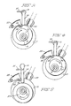
- Figures 3, 4 and 5 schematically illustrate the operation of the rotary compressor showing the piston in three sequential positions.
- Referring now to the drawing wherein like numerals indicate like elements throughout and particularly Figures 1 and 2 thereof, a dual flow single cell
rotary compressor 5 is shown which is typically situated in a hermetically sealed housing (not shown). The rotary compressor has aframe 7 defining a cylindrical aperture 11 and avane slot 13 extending radially outwardly from the cylindrical aperture. Ahollow shaft 15 is situated concentrically in the cylindrical aperture. The shaft is rotatably supported by a journal bearing 17 located in ajournal bearing plate 21 on one side and ajournal bearing plate 23 having a journal bearing 25 on the other. Theframe 7, thejournal bearing plate 21 and thejournal bearing plate 23 together define a cylindrical chamber. The portion of the shaft situated in the cylindrical chamber has an eccentrically positionedcircular lobe 27 extending therefrom. The circular lobe is surrounded by a close fitting annular member called arolling piston 31. The rolling piston is in contact with the circular lobe and a portion of the cylindrical wall of the chamber. The piston is free to rotate about the circular lobe. Avane 33 is slidably mounted in thevane slot 13 in the frame biased towards the piston contacting the piston by aspring 35. Anelectric motor rotor 37 is mounted on the portion of the shaft extending through thejournal bearing plate 21. The portion of the shaft extending through thejournal bearing plate 23 is closed off by acap 41 which has a friction fit. - The cylindrical chamber is in flow communication with a
first inlet port 43 extending radially outwardly from the cylindrical chamber through theframe 7 situated adjacent to one side of thevane 33. A check valve is not needed in this port. - A
second inlet port 52 extends axially inwardly through thecover plate 23. Acheck valve 53 is situated in this port and can comprise a ball check valve which permits flow into the cylindrical chamber but not out. The second inlet port is situated on the opposite side of thevane 33 from thefirst inlet port 43. - An
outlet port 55 extends from a position opposite from thesecond inlet port 52 axially through thejournal bearing plate 21 through a check valve. Areed check valve 57 is shown in the Figures comprising a flexible piece ofmetal 59 secured to the plate. A portion of theflexible piece 59 covers the outlet port permitting flow only from the cylindrical chamber. The exterior portion of thejournal bearing plate 21 is covered by a closefitting housing 61 which serves a muffler. - The
vane 33 divides the volume surrounding thepiston 31 into a high pressure and a low pressure region. The piston contacts the cylindrical chamber walls in a sweeping circular motion which moves in the same direction and at the same rate as theshaft 17 rotates. The operation of the compressor is shown in the sequence of schematic Figures 3, 4 and 5 showing different positions of the piston. The pressures used in describing the operation are those needed to operate the cycle described in US Patent 4910972, the description of which is incorporated herein by reference. Other pressures of course could be supplied and achieved by the rotary compressor. In the Figures the shaft rotates in the clockwise direction as viewed. - Referring now to Figure 3, low pressure vapor (17 psi) is admitted through the first inlet port. The
second inlet port 52 is covered by the face of the piston - In Figure 4, the
first inlet port 43 is covered by thepiston 31 and the second inlet port is uncovered admitting the higher pressure gas (39 psi). The higher pressure gas fills the chamber mixing with the lower pressure gas. - In Figure 5, the
piston 31 has rotated from the previous position in Figure 4 compressing the gas before it and out the outlet port at high pressure (150 psi). The compression ratio is approximately 8.8:1 in this configuration. By positioning the second inlet valve in the valve cover the size and location of the inlet valve can be changed without changing the frame. - The
shaft 17 is driven by an electric motor the stator of which is not shown. Thespring 35 holds thevane 33 against thepiston 31 during initial operation. Once the cycle starts the high pressure gas is discharged into the hermetically sealed housing (not shown) surrounding theframe 7. The high pressure gas pushes the vane against the piston. Tubes connected to the two inlet ports pass through the hermetically sealed housing the outlet tube is in flow communication with the housing. - The frame,
journal bearing plate 23 and journal plate can be fabricated from cast iron. The piston and vane can be fabricated from steel. - The foregoing has described a rotary compressor capable of pumping two separate refrigerant flows at different pressures through a single cavity to a higher pressure.
- While the invention has been described with respect to a preferred embodiment thereof, it will be understood by those skilled in the art that various changes in form and detail may be made without departing from the scope of the invention.
Claims (1)
- A rotary compressor comprising:
a frame defining a cylindrical aperture and a vane slot extending radially outwardly from said cylindrical aperture, said frame also defining a first inlet port extending radially outwardly from said cylindrical aperture through said frame on one side of said vane slot;
a vane slidably mounted in said vane slot;
a first journal bearing plate defining a journal bearing extending axially therethrough and defining a second inlet port extending axially inwardly through said first journal bearing plate, said second inlet port situated on the other side of said vane from said first inlet port;
a second journal bearing plate defining a journal bearing extending axially therethrough, said second journal bearing plate and said first journal bearing plate situated on either side of said cylindrical aperture defining a cylindrical chamber, said journal plate further defining an outlet port extending axially through said second journal bearing plate, said outlet port situated opposite said second inlet port;
a first check valve situated in said second inlet port for permitting flow only axially inwardly;
a second check valve situated in said outlet port for permitting flow only from said cylindrical chamber;
a shaft extending through said cylindrical chamber and rotatably mounted in the journal bearings of said first and second journal bearing plates, the portion of said shaft situated in said cylindrical chamber having an eccentrically extending circular lobe; and
a piston comprising an annular ring surrounding said circular lobe and contacting a portion of said cylindrical chamber periphery and both and journal bearing plates.
Applications Claiming Priority (2)
| Application Number | Priority Date | Filing Date | Title |
|---|---|---|---|
| US45986290A | 1990-01-02 | 1990-01-02 | |
| US459862 | 1990-01-02 |
Publications (1)
| Publication Number | Publication Date |
|---|---|
| EP0436330A1 true EP0436330A1 (en) | 1991-07-10 |
Family
ID=23826428
Family Applications (1)
| Application Number | Title | Priority Date | Filing Date |
|---|---|---|---|
| EP90313624A Withdrawn EP0436330A1 (en) | 1990-01-02 | 1990-12-14 | Dual flow single cell rotary compressor |
Country Status (2)
| Country | Link |
|---|---|
| EP (1) | EP0436330A1 (en) |
| CA (1) | CA2032787A1 (en) |
Cited By (1)
| Publication number | Priority date | Publication date | Assignee | Title |
|---|---|---|---|---|
| WO2003056184A1 (en) * | 2001-12-21 | 2003-07-10 | Wabco Automotive Uk Limited | Vacuum pump |
Families Citing this family (1)
| Publication number | Priority date | Publication date | Assignee | Title |
|---|---|---|---|---|
| CN108331755B (en) * | 2018-02-08 | 2023-11-10 | 珠海格力节能环保制冷技术研究中心有限公司 | Pump body assembly and compressor with same |
Citations (5)
| Publication number | Priority date | Publication date | Assignee | Title |
|---|---|---|---|---|
| US2095009A (en) * | 1932-05-10 | 1937-10-05 | Nash Kelvinator Corp | Refrigerating apparatus |
| US2299811A (en) * | 1938-02-26 | 1942-10-27 | Gen Motors Corp | Compressor for refrigerating apparatus |
| US2639855A (en) * | 1948-02-06 | 1953-05-26 | William T Daniels | Variable vacuum and pressure rotary pump |
| US4331002A (en) * | 1981-03-12 | 1982-05-25 | General Electric Company | Rotary compressor gas injection |
| US4622828A (en) * | 1983-08-25 | 1986-11-18 | Nippondenso Co., Ltd. | Air-conditioning and refrigerating system |
-
1990
- 1990-12-14 EP EP90313624A patent/EP0436330A1/en not_active Withdrawn
- 1990-12-20 CA CA 2032787 patent/CA2032787A1/en not_active Abandoned
Patent Citations (5)
| Publication number | Priority date | Publication date | Assignee | Title |
|---|---|---|---|---|
| US2095009A (en) * | 1932-05-10 | 1937-10-05 | Nash Kelvinator Corp | Refrigerating apparatus |
| US2299811A (en) * | 1938-02-26 | 1942-10-27 | Gen Motors Corp | Compressor for refrigerating apparatus |
| US2639855A (en) * | 1948-02-06 | 1953-05-26 | William T Daniels | Variable vacuum and pressure rotary pump |
| US4331002A (en) * | 1981-03-12 | 1982-05-25 | General Electric Company | Rotary compressor gas injection |
| US4622828A (en) * | 1983-08-25 | 1986-11-18 | Nippondenso Co., Ltd. | Air-conditioning and refrigerating system |
Cited By (2)
| Publication number | Priority date | Publication date | Assignee | Title |
|---|---|---|---|---|
| WO2003056184A1 (en) * | 2001-12-21 | 2003-07-10 | Wabco Automotive Uk Limited | Vacuum pump |
| US7207782B2 (en) | 2001-12-21 | 2007-04-24 | Wabco Automotive Uk Limited | Vacuum pump |
Also Published As
| Publication number | Publication date |
|---|---|
| CA2032787A1 (en) | 1991-07-03 |
Similar Documents
| Publication | Publication Date | Title |
|---|---|---|
| EP0222109B1 (en) | Multiple cylinder rotary compressor | |
| EP0168561B1 (en) | Scroll compressor | |
| CA2032417C (en) | Scroll compressor with discharge valves | |
| US6746223B2 (en) | Orbiting rotary compressor | |
| EP0510402A2 (en) | Orbiting rotary compressor | |
| JPS6037320B2 (en) | Scroll compressor | |
| US4990073A (en) | Two-cylinder rotary compressor having improved valve cover structure | |
| US11268511B2 (en) | Motor driven compressor apparatus including swing pin | |
| GB2166801A (en) | A scroll-type rotary fluid-compressor | |
| EP1177383A1 (en) | Small-sized compressor | |
| GB1595864A (en) | Motor compressor unit | |
| EP0436331A1 (en) | Dual flow single cell rotary compressor | |
| EP0436330A1 (en) | Dual flow single cell rotary compressor | |
| US4639198A (en) | Suction tube seal for a rotary compressor | |
| KR100758403B1 (en) | Hermetic Rotary Compressor | |
| JPS6111488A (en) | Scroll type compressor | |
| JP3249256B2 (en) | Oil pump for hermetic compressor | |
| EP1657443A1 (en) | Scroll compressor | |
| JPS59218380A (en) | scroll compressor | |
| KR100404109B1 (en) | Linear compressor | |
| JPS62199984A (en) | Scroll type compressor | |
| EP0122066A1 (en) | Scroll type fluid displacement apparatus with axial moving prevent device of bearing for driving mechanism | |
| US20060177336A1 (en) | Dual-piston valve for orbiting vane compressors | |
| US20260002533A1 (en) | Rotary compressor and refrigeration apparatus | |
| US20060177339A1 (en) | Horizontal type orbiting vane compressor |
Legal Events
| Date | Code | Title | Description |
|---|---|---|---|
| PUAI | Public reference made under article 153(3) epc to a published international application that has entered the european phase |
Free format text: ORIGINAL CODE: 0009012 |
|
| AK | Designated contracting states |
Kind code of ref document: A1 Designated state(s): DE ES FR GB IT |
|
| STAA | Information on the status of an ep patent application or granted ep patent |
Free format text: STATUS: THE APPLICATION IS DEEMED TO BE WITHDRAWN |
|
| 18D | Application deemed to be withdrawn |
Effective date: 19920111 |