EP0436395A2 - Vorrichtung zum Schneiden von Aramid mit hoher Geschwindigkeit - Google Patents
Vorrichtung zum Schneiden von Aramid mit hoher Geschwindigkeit Download PDFInfo
- Publication number
- EP0436395A2 EP0436395A2 EP90314367A EP90314367A EP0436395A2 EP 0436395 A2 EP0436395 A2 EP 0436395A2 EP 90314367 A EP90314367 A EP 90314367A EP 90314367 A EP90314367 A EP 90314367A EP 0436395 A2 EP0436395 A2 EP 0436395A2
- Authority
- EP
- European Patent Office
- Prior art keywords
- cutting element
- bore
- slot
- piston
- cutter
- Prior art date
- Legal status (The legal status is an assumption and is not a legal conclusion. Google has not performed a legal analysis and makes no representation as to the accuracy of the status listed.)
- Granted
Links
Images



Classifications
-
- D—TEXTILES; PAPER
- D01—NATURAL OR MAN-MADE THREADS OR FIBRES; SPINNING
- D01H—SPINNING OR TWISTING
- D01H9/00—Arrangements for replacing or removing bobbins, cores, receptacles, or completed packages at paying-out or take-up stations ; Combination of spinning-winding machine
-
- B—PERFORMING OPERATIONS; TRANSPORTING
- B65—CONVEYING; PACKING; STORING; HANDLING THIN OR FILAMENTARY MATERIAL
- B65H—HANDLING THIN OR FILAMENTARY MATERIAL, e.g. SHEETS, WEBS, CABLES
- B65H54/00—Winding, coiling, or depositing filamentary material
- B65H54/70—Other constructional features of yarn-winding machines
- B65H54/71—Arrangements for severing filamentary materials
-
- B—PERFORMING OPERATIONS; TRANSPORTING
- B65—CONVEYING; PACKING; STORING; HANDLING THIN OR FILAMENTARY MATERIAL
- B65H—HANDLING THIN OR FILAMENTARY MATERIAL, e.g. SHEETS, WEBS, CABLES
- B65H2701/00—Handled material; Storage means
- B65H2701/30—Handled filamentary material
- B65H2701/31—Textiles threads or artificial strands of filaments
-
- Y—GENERAL TAGGING OF NEW TECHNOLOGICAL DEVELOPMENTS; GENERAL TAGGING OF CROSS-SECTIONAL TECHNOLOGIES SPANNING OVER SEVERAL SECTIONS OF THE IPC; TECHNICAL SUBJECTS COVERED BY FORMER USPC CROSS-REFERENCE ART COLLECTIONS [XRACs] AND DIGESTS
- Y10—TECHNICAL SUBJECTS COVERED BY FORMER USPC
- Y10S—TECHNICAL SUBJECTS COVERED BY FORMER USPC CROSS-REFERENCE ART COLLECTIONS [XRACs] AND DIGESTS
- Y10S83/00—Cutting
- Y10S83/929—Particular nature of work or product
- Y10S83/949—Continuous or wound supply
- Y10S83/95—Strandlike
-
- Y—GENERAL TAGGING OF NEW TECHNOLOGICAL DEVELOPMENTS; GENERAL TAGGING OF CROSS-SECTIONAL TECHNOLOGIES SPANNING OVER SEVERAL SECTIONS OF THE IPC; TECHNICAL SUBJECTS COVERED BY FORMER USPC CROSS-REFERENCE ART COLLECTIONS [XRACs] AND DIGESTS
- Y10—TECHNICAL SUBJECTS COVERED BY FORMER USPC
- Y10T—TECHNICAL SUBJECTS COVERED BY FORMER US CLASSIFICATION
- Y10T83/00—Cutting
- Y10T83/525—Operation controlled by detector means responsive to work
- Y10T83/535—Release of interlock controlled
-
- Y—GENERAL TAGGING OF NEW TECHNOLOGICAL DEVELOPMENTS; GENERAL TAGGING OF CROSS-SECTIONAL TECHNOLOGIES SPANNING OVER SEVERAL SECTIONS OF THE IPC; TECHNICAL SUBJECTS COVERED BY FORMER USPC CROSS-REFERENCE ART COLLECTIONS [XRACs] AND DIGESTS
- Y10—TECHNICAL SUBJECTS COVERED BY FORMER USPC
- Y10T—TECHNICAL SUBJECTS COVERED BY FORMER US CLASSIFICATION
- Y10T83/00—Cutting
- Y10T83/525—Operation controlled by detector means responsive to work
- Y10T83/541—Actuation of tool controlled in response to work-sensing means
-
- Y—GENERAL TAGGING OF NEW TECHNOLOGICAL DEVELOPMENTS; GENERAL TAGGING OF CROSS-SECTIONAL TECHNOLOGIES SPANNING OVER SEVERAL SECTIONS OF THE IPC; TECHNICAL SUBJECTS COVERED BY FORMER USPC CROSS-REFERENCE ART COLLECTIONS [XRACs] AND DIGESTS
- Y10—TECHNICAL SUBJECTS COVERED BY FORMER USPC
- Y10T—TECHNICAL SUBJECTS COVERED BY FORMER US CLASSIFICATION
- Y10T83/00—Cutting
- Y10T83/869—Means to drive or to guide tool
- Y10T83/8759—With means to connect or disconnect tool and its drive
-
- Y—GENERAL TAGGING OF NEW TECHNOLOGICAL DEVELOPMENTS; GENERAL TAGGING OF CROSS-SECTIONAL TECHNOLOGIES SPANNING OVER SEVERAL SECTIONS OF THE IPC; TECHNICAL SUBJECTS COVERED BY FORMER USPC CROSS-REFERENCE ART COLLECTIONS [XRACs] AND DIGESTS
- Y10—TECHNICAL SUBJECTS COVERED BY FORMER USPC
- Y10T—TECHNICAL SUBJECTS COVERED BY FORMER US CLASSIFICATION
- Y10T83/00—Cutting
- Y10T83/869—Means to drive or to guide tool
- Y10T83/8776—Constantly urged tool or tool support [e.g., spring biased]
-
- Y—GENERAL TAGGING OF NEW TECHNOLOGICAL DEVELOPMENTS; GENERAL TAGGING OF CROSS-SECTIONAL TECHNOLOGIES SPANNING OVER SEVERAL SECTIONS OF THE IPC; TECHNICAL SUBJECTS COVERED BY FORMER USPC CROSS-REFERENCE ART COLLECTIONS [XRACs] AND DIGESTS
- Y10—TECHNICAL SUBJECTS COVERED BY FORMER USPC
- Y10T—TECHNICAL SUBJECTS COVERED BY FORMER US CLASSIFICATION
- Y10T83/00—Cutting
- Y10T83/869—Means to drive or to guide tool
- Y10T83/8821—With simple rectilinear reciprocating motion only
- Y10T83/8858—Fluid pressure actuated
Definitions
- Conventional cutting and winding operations for yarn include a doffing/donning operation often performed manually.
- an operator severs the yarn with scissors while the inlet of a suction or aspirator gun is held against the yarn at a point above the point of severing.
- a suction or aspirator gun is held against the yarn at a point above the point of severing.
- the tail end is wound onto a yam package while the newly formed leading end is sucked into the aspirator and fed to a waste collector.
- the suction gun is then placed onto a holder while the yam package is replaced with an empty tube core.
- the operator manipulates the suction gun to attach the yam to the rotating empty tube core and then severs the yam again by cutting or tension breaking at the suction gun so that the winding operation may continue. All the yam going to the suction gun during the transfer time is going to waste.
- U.S. Patent 4,496,109 issued on the application of Cardell, discloses such an auto transfer system where a signal furnished to the machine allows pressurized fluid to be supplied to a hydraulic cylinder.
- the hydraulic cylinder positions a cutter and yarn aspirator so that yarn enters the cutting slot of a stationary blade adjacent the aspirator. Air is then directed by a cam actuated valve causing pressure to build up in the working compartment of a cutter sleeve.
- a reciprocable blade moves forward in a line to surface contact with the stationary blade thereby severing the yam, the new leading end of which is aspirated to waste.
- the yams are then threaded onto new cores, snagged by pinch grooves on the cores, and are broken as the yam is placed in tension between the aspirator and rotating pinch grooves.
- More efficient winders for aramid fibers require auto sever, no waste, transfer devices to sever and transfer the yam from a full package to an empty tube core rapidly without aspirating any yarn to waste.
- This invention relates to a no waste transfer system in which a suction gun is not used to capture and transfer the yarn, but rather the yarn is snagged on an empty tube core and instantaneously severed from the full core without wasting any yam in the process. With some yams, the tension build-up during snagging is sufficient to break the yam and accomplish the severing. However for aramid fibers of moderate denier, the yam is exceptionally strong and does not break except at high force levels.
- an automatic cutting device which is actuated by the tension build-up in the yam is needed.
- the cutting device should be very reliable, since if a cut is not completed, the force necessary to break the yarn of higher denier is high enough to damage the winder.
- An automatic cutting device must also be extremely fast acting so that yam is cut quickly at the instant of snagging, since aramid yarn has very little elongation under load and the forces build up rapidly.
- an automatic cutting device should handle yarns with a wide variety of deniers, since it is most economical to use one cutter for a wide variety of. products.
- the present invention involves a yam cutting apparatus with a cutting mechanism having a cutter body, actuator means, cutting means and valve means.
- the cutter body has a bore with a slot extending transversely from a side of the body through the bore to a slot bottom wherein the slot is adpated to receive a yam which can be cut.
- the actuator means is pivotably affixed to the cutter body and adjacent to the bottom of the slot.
- the actuator means includes a yarn contact surface on an actuator arm which is located at one end of the cutter body and a valve shifting means at the other end of the cutter body. The actuator means pivots upon force exerted on its surface by contact with the yam.
- the cutting means which cuts the yam received in the slot as the actuator means pivots includes a stationary cutting element affixed to the cutter body adjacent one side of the bore at the side of the slot opposite a first end of the bore and forming at least one edge of the slot, a piston slideably fitted into the bore and adapted to move from the first end of the bore toward the slot as a result of a valve means directing the pressurized fluid to the first end of the bore, a moveable cutting element affixed to the piston and adapted to pass by the stationary cutting element as the piston moves toward the slot, a biasing means to urge the moveable and stationary cutting elements, one against the other, thereby cutting the yam received in the slot as the moveable cutting element passes by the stationary cutting element, and a spring biasing means to urge the piston against the first end of the bore.
- the valve means is attached to the cutter body adjacent a first end of the bore and adapted to be controlled by a valve shifting means.
- the valve means directs the cutting means toward the yarn to be cut and includes the valve shifting means, a shiftable element, a valve body, and ports for selectively directing pressurized fluid from a source to the first end of the bore and from the bore to the atmosphere allowing the piston to slide toward the stationary cutting element against the urging of the spring biasing means.
- the cutter body can be considered to include the cutter body, itself, and the cutting means.
- the tensioned yam passes over the yam contact surface on the actuator arm and through the cutting slot in the cutter body.
- the yam causes the actuator means to pivot and raises the valve shifting means allowing the valve means to direct pressurized air to force the piston which has an attached moveable cutting element to slide across the stationary cutting element which is affixed to the cutter body.
- the moveable cutting element and the stationary cutting element are urged, one against the other, by a biasing means ; preferably by an appropriately positioned pair of elastomeric O rings.
- the piston with the attached moveable cutting element may be prevented from rotating in a cylinder bore by an anti-rotational pin.
- the actuator arm may have a sharp angled edge on the yam contact surface which can serve as a secondary cutter.
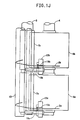
- FIG. 1J shows yarns 2a and 2b in slots 19a and 19b just before snagging and the commencement of winding on cores 7a and 7b.
- FIG. 1F the empty tube core 7 is shown to be approaching bale roll 13 ready to begin winding yarn which is still being wound on full package 6.
- snagging devices on chuck 5 (not shown) grab the yam and start wrapping it on rotating empty tube core 7,as shown in FIG. 1 G.
- the tensioned yam actuates an air driven primary cutting mechanism in the cutter, to cut the yam.
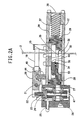
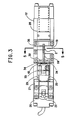
- FIGS. 2A AND 3 show one embodiment of the cutter featuring a cutter body 12 having a slot 19 extending transversely through a bore 28 in the body wherein a yam strand 2 may be accepted ; an actuator means pivotably affixed to the cutter body 12, the actuator means including a yarn contact surface 18 and a valve shifting means 22; a valve means attached to, or part of, body 12 and including a shiftable element 24 connected to the actuator means, the element acting to alternatively direct a pressurized fluid from a source entering at port 25 to a first end of bore 28 through port 27 or from bore 28 to the atmosphere through port 47 ; a cutting means including a slotted piston 29 moveable by the fluid pressure directed into bore 28, the piston having a moveable cutting element30 attached, which when moved by the piston is positioned to traverse slot 19 and pass by a stationary cutting edge on cutting element 32 fixed to body 12 at the side of the slot furthest from the first end of the bore, the cutting elements urged one against the other thereby cutting any yarn received in the slot.
- the actuator means is attached to the body 12 by pivot pin 21 passing through clamp 20.
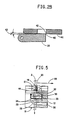
- the actuator includes an arm 45 having a yam contact surface 18 which is shown in FIG. 5 with a sharp angled edge, 50 with the arm held in clamp 20 pivotable about pivot 21, as shown in FIG. 2A.
- a valve pin 22 engages the end 23 of a shiftable element 24 which resembles a piston.
- Spring 44 pivotally urges clamp 20 and attached yarn contact surface 18 away from body 12 and urges shifting means 22 toward body 12 thereby forcing shiftable element 24 downward until it seals off the pressurized fluid from port 25.
- FIG 5 when yam 2 is pulled in the direction of arrow 55, there is a net force acting on surface 18 of arm 45 which compresses spring 44 and pivots clamp 20 and thereby raises shiftable element 24 (See, also, FIG. 2A).
- the valve means has valve body 26 supplied with pressurized air through port 25.
- Port 27 provides fluid communication between valve body 26 and cylinder bore 28 where the pressurized air acts on one end of slotted piston 29.
- Port 47 is an exhaust port from valve body 26 to direct pressurized airfrom bore 28 through port 27 to the atmosphere.
- actuator arm 45 when there is no yarn 2 under tension acting against surface 18, actuator arm 45 is not depressed and shiftable element 24 is in the closed position.
- pressurized air from port 25 is blocked from bore 28, exhaust port 47 is open, and no pressure acts on piston 29.
- the sharp angled edge 50 on the actuator arm 45 may provide a back-up or secondary cutting capability so that cutting of light denier yarns is assured, but at a high tension.
- the cutting means of FIGS 2A, 3 and 5 comprise a piston 29 slidably fitted into the bore 28, a pivotable cutting element 30 mounted on the piston 29, and a fixed cutting element 32 mounted at the side of bore 28 with the cutting edge 42 (FIG. 2B) located at the side of the slot furthest from a first end of the bore where the pressurized fluid is admitted at port 27.
- a spring 37 between body 12 and piston 29, urges piston 29 against the first end of the bore.
- Moveable cutting element 30 is pivotably mounted to piston 29 at pivot point 33.
- Resiliant biasing means 34 placed between the piston and moveable cutting element can consist of elastomeric "O rings" that uniformly direct moveable cutting element 30 away from piston 29 and holds it against the flat surface of stationary cutting element 32 which is rigidly attached to the housing of the cutting body. It has been determined that elastomeric O rings having a durometer of 85 are, generally suitable. Larger denier yarns can use O rings of greater hardness and smaller denier may be able to use O rings of lower hardness. Piston 29 is closely guided in cylinder bore 28 and is prevented from rotating by the sliding contact of cutout 35 in the piston with an anti-rotational pin 36 in the cylinder bore 28. During the cutting stroke of the piston, spring 37 is compressed and air to the right of the piston is forced out of the cylinder bore 28 through opening 38.
- FIG 2A shows an embodiment wherein the moveable cutting element is pivotable.
- the cutting elements are closely guided so that a line to surface contact occurs continuously between the two cutting edges as they pass by each other to cut the yarn. It is also important that the cutting edges are urged together with uniform loading.
- the elastomeric O rings are preferrred for such urging.
- FIG. 2B further shows this line to surface contact.
- the contact between cutting edge 40 of moveable cutting element 30 and the surface 41 of stationary cutting element 32 is a line to surface contact
- a line to surface contact is important in order that, as cutting edge 40 slides across cutting edge 42 of stationary cutting element 32, the yarn is cleanly cut. Any gaps or separation between the cutting edges would result in an incomplete and ragged cut.
- the line to surface contact is achieved by providing an angle of about two degrees at43 between moveable cutting element 30 and stationary cutting element 32.
- FIGS. 3 and 5 show an overhead view and section view, respectively, of FIG. 2A in which the resiliant biasing means, consisting of two elastomeric O Rings 34, located between piston 29 and moveable cutting element 30, urges the moveable cutting element 30 away from piston 29 and towards stationary cutting element 32, thus insuring that the cutting edges are urged together with uniform loading.
- the resiliant biasing means consisting of two elastomeric O Rings 34, located between piston 29 and moveable cutting element 30, urges the moveable cutting element 30 away from piston 29 and towards stationary cutting element 32, thus insuring that the cutting edges are urged together with uniform loading.
- Close tolerancing of the cutting means parts and careful assembly which may include shim spacing under the O rings to get the desired O ring compression, may be required to assure a significant load between the cutting elements.
- the cutting elements are constructed of materials that will slide readily against one another and will withstand many cycles of reliable cutting.
- One material which is known to work well is C-2 grade tungsten carbide having a finish at the cutting edge that is finer than 20 microinches and is coated with chemical vapor deposition coatings of 2 microns of titanium carbide and further coated with 2 microns of titanium nitride.
- Another material which is known to work well is alumina ceramic, one version of which is called Aremcolox, grade 502-1400, furnished by Aremco Products, Inc. in Ossining, New York, USA.
- the alumina ceramic should also have a finish finer than 20 microinches.
- the same materials can be used for both cutting edges or different materials can be used for each edge. The combination of these materials with the line contact of the cutting elements and the resilient loading of the elements against one another produces surprisingly reliable, long life cutting.
- spring 44 moves clamp 20 up and shiftable element 24 is moved down. Moving the shiftable element down, opens vent port 47 and blocks supply port 25.
- Spring biasing means 37 acting on piston 29 returns the piston and moveable cutting element 30 to its original position, thereby clearing slot 19 for introduction of the next yam to be cut.
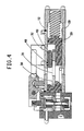
- FIGS. 4 and 6 show an embodiment of a cutter of this invention in which stationary cutting element 32 is pivotable ; and moveable cutting element 30 is part of a slotted bar 31 which is attached to piston 29.
- Stationary cutting element 32 is pivotably mounted to cutter body 12 at pivot 49.
- a resilient biasing means consisting of elastomeric O rings 48 urges stationary cutting element 32 away from cutter body 12 and holds it against moveable cutting element 30.
- the cutting element 30, of slotted bar 31 may be shaped in a way that guides the yarn into the cutting zone at the moment of cutting. This shaped cutting edge is an advantage if there is low tension on the yam.
- the shape also provides a balanced contact of the elements on both sides of the yam at the moment of cutting. Repetition of the shape at the opposite end of moveable cutting element 30 permits flipping the element to provide a fresh cutting edge.
- the cutting of the yarn occurs very rapidly before any damaging tension is created.
- the high speed of the cut is a result of the direct connection between the actuator arm and the valve, the short distance the air must travel to the piston, and the relatively short distance the piston (with the attached moveable cutting element) must travel to cut the yarn.
- the piston moves a sufficient distance to allow the moveable cutting element to develop a high speed in order that it can rapidly cut the yarn against the stationary cutting element.
- the cutter has been surprisingly effective in cutting aramid yams with a wide range of deniers.
- the tensioned yam can be cut by the secondary cutter, that is, the sharp edge 18 of the actuator arm ; for deniers of from about 800 to 7500, the tensioned yam deflects the actuator arm and the primary cutter elements 30 and 32 cut the yarn.
- the secondary cutter that is, the sharp edge 18 of the actuator arm
- the tensioned yam deflects the actuator arm and the primary cutter elements 30 and 32 cut the yarn.
- 3000 denier poly(p-phenylene terephthalamide) yam winding at about 1000 yds/min over 2000 cuts were made without failure.
- Such reliable long lasting cutting operation has not been obtained with other known shear cutters or with impact or grinding type cutters.
Landscapes
- Engineering & Computer Science (AREA)
- Textile Engineering (AREA)
- Mechanical Engineering (AREA)
- Spinning Methods And Devices For Manufacturing Artificial Fibers (AREA)
- Treatment Of Fiber Materials (AREA)
- Coiling Of Filamentary Materials In General (AREA)
- Disintegrating Or Milling (AREA)
- Preliminary Treatment Of Fibers (AREA)
- Processing Of Stones Or Stones Resemblance Materials (AREA)
- Mechanical Treatment Of Semiconductor (AREA)
Applications Claiming Priority (2)
| Application Number | Priority Date | Filing Date | Title |
|---|---|---|---|
| US07/461,470 US5033345A (en) | 1989-12-28 | 1989-12-28 | High-speed cutter for aramids |
| US461470 | 1989-12-28 |
Publications (3)
| Publication Number | Publication Date |
|---|---|
| EP0436395A2 true EP0436395A2 (de) | 1991-07-10 |
| EP0436395A3 EP0436395A3 (en) | 1992-02-26 |
| EP0436395B1 EP0436395B1 (de) | 1997-12-10 |
Family
ID=23832694
Family Applications (1)
| Application Number | Title | Priority Date | Filing Date |
|---|---|---|---|
| EP90314367A Expired - Lifetime EP0436395B1 (de) | 1989-12-28 | 1990-12-28 | Vorrichtung zum Schneiden von Aramid mit hoher Geschwindigkeit |
Country Status (10)
| Country | Link |
|---|---|
| US (1) | US5033345A (de) |
| EP (1) | EP0436395B1 (de) |
| JP (1) | JPH04133972A (de) |
| KR (1) | KR0161976B1 (de) |
| CN (1) | CN1029138C (de) |
| AT (1) | ATE161000T1 (de) |
| AU (1) | AU631038B2 (de) |
| CA (1) | CA2032806A1 (de) |
| DE (1) | DE69031798T2 (de) |
| IE (1) | IE904661A1 (de) |
Cited By (3)
| Publication number | Priority date | Publication date | Assignee | Title |
|---|---|---|---|---|
| RU2161214C2 (ru) * | 1995-06-29 | 2000-12-27 | Е.И.Дюпон Де Немур Энд Компани | Резальное устройство для пряжи |
| DE10050692A1 (de) * | 2000-10-13 | 2002-04-18 | Schlafhorst & Co W | Fadenklemm- und schneideinrichtung |
| WO2013017694A1 (de) * | 2011-08-03 | 2013-02-07 | Oerlikon Textile Gmbh & Co. Kg | Aufspulvorrichtung |
Families Citing this family (7)
| Publication number | Priority date | Publication date | Assignee | Title |
|---|---|---|---|---|
| US5150640A (en) * | 1989-12-28 | 1992-09-29 | E. I. Du Pont De Nemours And Company | High-speed cutter for yarns |
| CN102866244B (zh) * | 2012-09-03 | 2014-12-17 | 天津工业大学 | 一种线状纺织品取样称重装置及应用该装置的测试仪 |
| US9862564B2 (en) | 2013-10-25 | 2018-01-09 | Columbia Insurance Company | Cutter assembly for stretched yarn |
| CN105951233B (zh) * | 2016-06-21 | 2018-04-20 | 天津工业大学 | 一种粗纱剪断装置 |
| CN110054020B (zh) * | 2019-06-02 | 2020-11-20 | 新沂市锡沂高新材料产业技术研究院有限公司 | 一种医用不锈钢丝的卷料装置 |
| CN111826753A (zh) * | 2020-06-09 | 2020-10-27 | 崔建中 | 一种熔喷超细纤维专用喷气纺纱系统的收集结构 |
| CN117418336B (zh) * | 2023-11-20 | 2025-12-02 | 卓郎(江苏)纺织机械有限公司 | 移动式落纱头和落纱小车 |
Family Cites Families (23)
| Publication number | Priority date | Publication date | Assignee | Title |
|---|---|---|---|---|
| US2783838A (en) * | 1955-01-13 | 1957-03-05 | United Shoe Machinery Corp | Safety device for a press comprising stroke terminating means |
| US2919794A (en) * | 1958-07-28 | 1960-01-05 | Celanese Corp | Tow brake |
| US3527422A (en) * | 1968-12-31 | 1970-09-08 | Celanese Corp | High speed traverse mechanism |
| CH512390A (de) * | 1970-03-06 | 1971-09-15 | Heberlein & Co Ag | Vorrichtung zum Erfassen mindestens eines Fadens und Aufbringen desselben auf eine Aufwickelhülse |
| US3760674A (en) * | 1971-10-28 | 1973-09-25 | Mine Safety Appliances Co | Explosively actuated underwater anchor line cutter |
| US3854356A (en) * | 1973-07-17 | 1974-12-17 | Amf Inc | Thread cutting and clamping means |
| CH572435A5 (de) * | 1973-12-22 | 1976-02-13 | Barmag Barmer Maschf | |
| US4033519A (en) * | 1974-06-06 | 1977-07-05 | Teijin Limited | Method and apparatus for automatically changing bobbins and winding yarn continuously |
| GB1463222A (en) * | 1974-07-01 | 1977-02-02 | Barmag Barmer Maschf | Winding device |
| CH587767A5 (de) * | 1974-11-15 | 1977-05-13 | Rieter Ag Maschf | |
| CH598118A5 (de) * | 1974-11-21 | 1978-04-28 | Barmag Barmer Maschf | |
| CH578477A5 (en) * | 1974-12-06 | 1976-08-13 | Zellweger Uster Ag | Thread presence detection system - has single parameter centrally set for all the measuring devices |
| DD122503A1 (de) * | 1974-12-23 | 1976-10-12 | ||
| CH593855A5 (de) * | 1975-04-16 | 1977-12-15 | Rieter Ag Maschf | |
| CH593856A5 (de) * | 1975-04-16 | 1977-12-15 | Rieter Ag Maschf | |
| US4078736A (en) * | 1975-06-20 | 1978-03-14 | Celanese Corporation | Automatic doffing method |
| DE2724143C2 (de) * | 1977-05-27 | 1983-06-09 | Alfred 8000 München Lemmer | Schneidvorrichtung zum Abschneiden der unten aus einer gedruckten Leiterplatte herausschauenden Anschlußdraht- Enden der Bauelemente |
| US4099679A (en) * | 1977-07-20 | 1978-07-11 | Eastman Kodak Company | Dual yarn tie-up and transfer tail apparatus |
| US4496109A (en) * | 1981-04-28 | 1985-01-29 | Celanese Corporation | Apparatus for cutting, aspirating and rethreading a traveling filamentary yarn |
| DE3132853A1 (de) * | 1981-08-20 | 1983-03-03 | Neumünstersche Maschinen- und Apparatebau GmbH (Neumag), 2350 Neumünster | Spulmaschine fuer automatische spulenwechsel |
| US4789277A (en) * | 1986-02-18 | 1988-12-06 | Advanced Composite Materials Corporation | Method of cutting using silicon carbide whisker reinforced ceramic cutting tools |
| US4716801A (en) * | 1986-08-15 | 1988-01-05 | Eastman Kodak Company | Rapid cut-off apparatus for high speed moving yarn |
| US4872381A (en) * | 1988-07-13 | 1989-10-10 | International Business Machines Corp. | Programmable magnetic repulsion punching apparatus |
-
1989
- 1989-12-28 US US07/461,470 patent/US5033345A/en not_active Expired - Lifetime
-
1990
- 1990-12-20 CA CA002032806A patent/CA2032806A1/en not_active Abandoned
- 1990-12-21 IE IE466190A patent/IE904661A1/en not_active Application Discontinuation
- 1990-12-28 EP EP90314367A patent/EP0436395B1/de not_active Expired - Lifetime
- 1990-12-28 DE DE69031798T patent/DE69031798T2/de not_active Expired - Fee Related
- 1990-12-28 AT AT90314367T patent/ATE161000T1/de not_active IP Right Cessation
- 1990-12-28 JP JP2415915A patent/JPH04133972A/ja active Pending
- 1990-12-28 KR KR1019900022219A patent/KR0161976B1/ko not_active Expired - Fee Related
- 1990-12-28 AU AU68529/90A patent/AU631038B2/en not_active Ceased
- 1990-12-28 CN CN91100741A patent/CN1029138C/zh not_active Expired - Fee Related
Cited By (3)
| Publication number | Priority date | Publication date | Assignee | Title |
|---|---|---|---|---|
| RU2161214C2 (ru) * | 1995-06-29 | 2000-12-27 | Е.И.Дюпон Де Немур Энд Компани | Резальное устройство для пряжи |
| DE10050692A1 (de) * | 2000-10-13 | 2002-04-18 | Schlafhorst & Co W | Fadenklemm- und schneideinrichtung |
| WO2013017694A1 (de) * | 2011-08-03 | 2013-02-07 | Oerlikon Textile Gmbh & Co. Kg | Aufspulvorrichtung |
Also Published As
| Publication number | Publication date |
|---|---|
| AU6852990A (en) | 1991-07-04 |
| EP0436395A3 (en) | 1992-02-26 |
| DE69031798D1 (de) | 1998-01-22 |
| KR910012397A (ko) | 1991-08-07 |
| IE904661A1 (en) | 1991-07-17 |
| KR0161976B1 (ko) | 1998-12-01 |
| CN1055019A (zh) | 1991-10-02 |
| AU631038B2 (en) | 1992-11-12 |
| US5033345A (en) | 1991-07-23 |
| CN1029138C (zh) | 1995-06-28 |
| JPH04133972A (ja) | 1992-05-07 |
| EP0436395B1 (de) | 1997-12-10 |
| ATE161000T1 (de) | 1997-12-15 |
| DE69031798T2 (de) | 1998-07-09 |
| CA2032806A1 (en) | 1991-06-29 |
Similar Documents
| Publication | Publication Date | Title |
|---|---|---|
| US4108388A (en) | Method for catching, severing and rethreading a thread and an apparatus for implementing the method | |
| EP0436395B1 (de) | Vorrichtung zum Schneiden von Aramid mit hoher Geschwindigkeit | |
| US5005776A (en) | Process and device to guide and sever a thread upon bobbin replacement | |
| US3948452A (en) | Open-end spinning machine and method of operating the same | |
| US6457668B1 (en) | Apparatus and method for guiding and cutting an advancing yarn during a package doff | |
| US3678579A (en) | Yarn control apparatus | |
| US5016829A (en) | Takeup machine | |
| US4173311A (en) | Device for cutting yarn on ball winding machines | |
| US3974972A (en) | Apparatus for forming a reserve winding on a yarn spool | |
| US4210293A (en) | Strand transfer | |
| JPH09156831A (ja) | 綾巻きパッケージを巻成する繊維機械の綾巻きパッケージ交換装置 | |
| CZ20022313A3 (cs) | Servisní zařízení k opětovnému zapřadení na pracovních místech dopřádacího stroje | |
| US5634602A (en) | Open end spinning machine with associated service device | |
| US5150640A (en) | High-speed cutter for yarns | |
| US4613090A (en) | Yarn winding apparatus of automatic bobbin changing type | |
| US4437617A (en) | Winding apparatus for filamentary material having means for winding a trailing end of the filamentary material in close order upon a package | |
| US4496109A (en) | Apparatus for cutting, aspirating and rethreading a traveling filamentary yarn | |
| EP0063932B1 (de) | Vorrichtung zum Schneiden, Ansaugen und Einfädeln eines laufenden Garns | |
| SK18232002A3 (sk) | Zariadenie a spôsob rozrezávania káblov vytvorených z termoplastických vlákien | |
| JPH07115801B2 (ja) | 繊維機械に用いられる糸キャリッジから残糸を除く方法および装置 | |
| US4948058A (en) | Apparatus and method for winding yarn | |
| CZ307292A3 (en) | Device for breakage of a fiber sliver in a filling station of a textile machine | |
| US7290732B2 (en) | Systems, apparatuses and methods for cutting and spooling paper | |
| US4607482A (en) | Fluid yarn splicing device | |
| JPH0158110B2 (de) |
Legal Events
| Date | Code | Title | Description |
|---|---|---|---|
| PUAI | Public reference made under article 153(3) epc to a published international application that has entered the european phase |
Free format text: ORIGINAL CODE: 0009012 |
|
| AK | Designated contracting states |
Kind code of ref document: A2 Designated state(s): AT BE DE ES FR GB GR IT LU NL |
|
| PUAL | Search report despatched |
Free format text: ORIGINAL CODE: 0009013 |
|
| AK | Designated contracting states |
Kind code of ref document: A3 Designated state(s): AT BE DE ES FR GB GR IT LU NL |
|
| 17P | Request for examination filed |
Effective date: 19920508 |
|
| 17Q | First examination report despatched |
Effective date: 19940127 |
|
| GRAG | Despatch of communication of intention to grant |
Free format text: ORIGINAL CODE: EPIDOS AGRA |
|
| GRAH | Despatch of communication of intention to grant a patent |
Free format text: ORIGINAL CODE: EPIDOS IGRA |
|
| GRAH | Despatch of communication of intention to grant a patent |
Free format text: ORIGINAL CODE: EPIDOS IGRA |
|
| GRAA | (expected) grant |
Free format text: ORIGINAL CODE: 0009210 |
|
| AK | Designated contracting states |
Kind code of ref document: B1 Designated state(s): AT BE DE ES FR GB GR IT LU NL |
|
| PG25 | Lapsed in a contracting state [announced via postgrant information from national office to epo] |
Ref country code: GR Free format text: LAPSE BECAUSE OF FAILURE TO SUBMIT A TRANSLATION OF THE DESCRIPTION OR TO PAY THE FEE WITHIN THE PRESCRIBED TIME-LIMIT Effective date: 19971210 Ref country code: AT Free format text: LAPSE BECAUSE OF FAILURE TO SUBMIT A TRANSLATION OF THE DESCRIPTION OR TO PAY THE FEE WITHIN THE PRESCRIBED TIME-LIMIT Effective date: 19971210 Ref country code: BE Free format text: LAPSE BECAUSE OF FAILURE TO SUBMIT A TRANSLATION OF THE DESCRIPTION OR TO PAY THE FEE WITHIN THE PRESCRIBED TIME-LIMIT Effective date: 19971210 Ref country code: ES Free format text: THE PATENT HAS BEEN ANNULLED BY A DECISION OF A NATIONAL AUTHORITY Effective date: 19971210 |
|
| REF | Corresponds to: |
Ref document number: 161000 Country of ref document: AT Date of ref document: 19971215 Kind code of ref document: T |
|
| PG25 | Lapsed in a contracting state [announced via postgrant information from national office to epo] |
Ref country code: LU Free format text: LAPSE BECAUSE OF NON-PAYMENT OF DUE FEES Effective date: 19971228 |
|
| REF | Corresponds to: |
Ref document number: 69031798 Country of ref document: DE Date of ref document: 19980122 |
|
| ITF | It: translation for a ep patent filed | ||
| ET | Fr: translation filed | ||
| PLBE | No opposition filed within time limit |
Free format text: ORIGINAL CODE: 0009261 |
|
| STAA | Information on the status of an ep patent application or granted ep patent |
Free format text: STATUS: NO OPPOSITION FILED WITHIN TIME LIMIT |
|
| 26N | No opposition filed | ||
| REG | Reference to a national code |
Ref country code: GB Ref legal event code: IF02 |
|
| PGFP | Annual fee paid to national office [announced via postgrant information from national office to epo] |
Ref country code: FR Payment date: 20050825 Year of fee payment: 16 |
|
| PGFP | Annual fee paid to national office [announced via postgrant information from national office to epo] |
Ref country code: NL Payment date: 20051204 Year of fee payment: 16 |
|
| PGFP | Annual fee paid to national office [announced via postgrant information from national office to epo] |
Ref country code: DE Payment date: 20051222 Year of fee payment: 16 |
|
| PG25 | Lapsed in a contracting state [announced via postgrant information from national office to epo] |
Ref country code: IT Free format text: LAPSE BECAUSE OF NON-PAYMENT OF DUE FEES;WARNING: LAPSES OF ITALIAN PATENTS WITH EFFECTIVE DATE BEFORE 2007 MAY HAVE OCCURRED AT ANY TIME BEFORE 2007. THE CORRECT EFFECTIVE DATE MAY BE DIFFERENT FROM THE ONE RECORDED. Effective date: 20051228 |
|
| PGFP | Annual fee paid to national office [announced via postgrant information from national office to epo] |
Ref country code: GB Payment date: 20051228 Year of fee payment: 16 |
|
| PG25 | Lapsed in a contracting state [announced via postgrant information from national office to epo] |
Ref country code: NL Free format text: LAPSE BECAUSE OF NON-PAYMENT OF DUE FEES Effective date: 20070701 |
|
| PG25 | Lapsed in a contracting state [announced via postgrant information from national office to epo] |
Ref country code: DE Free format text: LAPSE BECAUSE OF NON-PAYMENT OF DUE FEES Effective date: 20070703 |
|
| GBPC | Gb: european patent ceased through non-payment of renewal fee |
Effective date: 20061228 |
|
| NLV4 | Nl: lapsed or anulled due to non-payment of the annual fee |
Effective date: 20070701 |
|
| REG | Reference to a national code |
Ref country code: FR Ref legal event code: ST Effective date: 20070831 |
|
| PG25 | Lapsed in a contracting state [announced via postgrant information from national office to epo] |
Ref country code: GB Free format text: LAPSE BECAUSE OF NON-PAYMENT OF DUE FEES Effective date: 20061228 |
|
| PG25 | Lapsed in a contracting state [announced via postgrant information from national office to epo] |
Ref country code: FR Free format text: LAPSE BECAUSE OF NON-PAYMENT OF DUE FEES Effective date: 20070102 |