EP0436406A2 - Autoantenne - Google Patents
Autoantenne Download PDFInfo
- Publication number
- EP0436406A2 EP0436406A2 EP90402997A EP90402997A EP0436406A2 EP 0436406 A2 EP0436406 A2 EP 0436406A2 EP 90402997 A EP90402997 A EP 90402997A EP 90402997 A EP90402997 A EP 90402997A EP 0436406 A2 EP0436406 A2 EP 0436406A2
- Authority
- EP
- European Patent Office
- Prior art keywords
- antenna
- radio
- car phone
- car
- rod
- Prior art date
- Legal status (The legal status is an assumption and is not a legal conclusion. Google has not performed a legal analysis and makes no representation as to the accuracy of the status listed.)
- Withdrawn
Links
Images


Classifications
-
- H—ELECTRICITY
- H01—ELECTRIC ELEMENTS
- H01Q—ANTENNAS, i.e. RADIO AERIALS
- H01Q1/00—Details of, or arrangements associated with, antennas
- H01Q1/27—Adaptation for use in or on movable bodies
- H01Q1/32—Adaptation for use in or on road or rail vehicles
- H01Q1/325—Adaptation for use in or on road or rail vehicles characterised by the location of the antenna on the vehicle
- H01Q1/3283—Adaptation for use in or on road or rail vehicles characterised by the location of the antenna on the vehicle side-mounted antennas, e.g. bumper-mounted, door-mounted
-
- H—ELECTRICITY
- H01—ELECTRIC ELEMENTS
- H01Q—ANTENNAS, i.e. RADIO AERIALS
- H01Q1/00—Details of, or arrangements associated with, antennas
- H01Q1/02—Arrangements for de-icing; Arrangements for drying-out ; Arrangements for cooling; Arrangements for preventing corrosion
-
- H—ELECTRICITY
- H01—ELECTRIC ELEMENTS
- H01Q—ANTENNAS, i.e. RADIO AERIALS
- H01Q1/00—Details of, or arrangements associated with, antennas
- H01Q1/08—Means for collapsing antennas or parts thereof
- H01Q1/10—Telescopic elements
-
- H—ELECTRICITY
- H01—ELECTRIC ELEMENTS
- H01Q—ANTENNAS, i.e. RADIO AERIALS
- H01Q5/00—Arrangements for simultaneous operation of antennas on two or more different wavebands, e.g. dual-band or multi-band arrangements
- H01Q5/40—Imbricated or interleaved structures; Combined or electromagnetically coupled arrangements, e.g. comprising two or more non-connected fed radiating elements
Definitions
- the present invention relates to a structure of car phone antenna for use in automobiles.
- a radio antenna and a car phone antenna are separately provided, and although the radio antenna can be installed in a hidable form, the car phone antenna has to be installed in such a fixed form that the antenna should be fixedly exposed to the outside of the automobile. Accordingly, even when the car phone is not used, the car phone antenna is exposed to the outside of the automobile in an elongate form, with the result that the aesthetic appearance of the automobile is aggravated, and that the antenna can not be protected from various external forces.
- the present invention is intended to overcome the above described disadvantages of the conventional devices.
- the device of the present invention is constituted such that a wire is wound on a rotary body of a wire winding unit, the wire can be wound or unwound by a motor, and consequently, a car phone antenna stored in an antenna storing tube can be extended to the outside or can be contracted into the antenna storing tube.
- the car phone antenna is let to be extended to the outside only when the car phone is used, and further, this antenna can also be used for the car radio, thereby making the antenna serve for both the car phone and the car radio, i.e., two functions with a single antenna.
- the antenna is so constituted as to transfer the signals directly from the antenna, and the antenna has various other advantages such as an extension of the life expectancy of the antenna without hurting the aesthetic appearance of the automobile, a high sensitivity functions of the car radio and the car phone, and the like.
- the automobile antenna according to the present invention is installed within the body 4 of the automobile, in such a manner that an antenna storing tube storing a car phone antenna 9 is fixedly installed within the car body 4, and near the lower end of the antenna storing tube 5, there is installed a wire winding unit WR which is also attached to the car body 4 and which is also connected to a motor M.
- the antenna storing tube 5 is fixedly attached to the car body and within the car trunk by means of a fastening nut 17 and the like, and a rubber cap 24 is installed under an antenna top 23 so that the intrusions of rain drops and moisture should be prevented, and that impacts should be absorbed during the descending of the antenna.
- a freeze preventing device D is installed around and enclosing the antenna storing tube 5, and the freeze preventing device comprises a temperature detecting sensor S, a coil C and a power terminal T. If the temperature of the antenna storing tube 5 drops below 0°C, the freeze preventing device is activated by the temperature detecting sensor S, so that the antenna storing tube 5 should be maintained at a constant temperature, thereby keeping the radio antenna rod 10 of the antenna storing tube 5 from being frozen.
- the wire winding unit WR which is for actuating the car phone antenna 9 and the radio antenna rod 10 includes a wire winding body 1, a rotary body 2 and a covering cap 7, and the rotary body 2 with a wire 3 wound thereon is installed within the wire winding body 1.
- a worm gear 21 which is concentrically installed to a revolution shaft 22 of the rotary body 2 is meshed with a worm 20 which is connected to the shaft of the motor M, so that the rotary body 2 should be able to revolve forwardly or reversely in accordance with the revolution direction of the motor M.
- the other end of the wire 3 which is wound on the rotary body 2 is connected through a connecting tube 1b of the wire winding body 1 to the leading end of a telescopically extendable car phone antena rod 6 which is connected to a plug 11 of the car phone antenna 9, so that the wire 3 should be able to lift and lower the car phone antenna 9 in accordance with the revolution direction of the rotary body 2.
- the radio antenna rod 10 and the car phone antenna 9 are stored within the antenna storing tube 5 in the cited order, and the car phone antenna 9 is insulatingly supported by a sliding rod 12, while the sliding rod 12 also moves up and down within the radio antenna rod 10 in order to lift or lower the radio antenna rod 10.
- the radio antenna rod 10 is provided with teflon rings 30, 31 on which water channels 30a, 31a are formed in order to facilitate the draining of water from the antenna storing tube 5. Further, between the teflon rings 30, 31, there is installed a conductive spring ring 32 which has a discontinuous opening, so that the radio antenna rod 10 and the antenna storing tube 5 should be electrically interconnected.
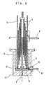
- the signals are directly transferred from the car phone antenna 9, and an actuating member is used in order to extend and contract the car phone antenna 9. That is, as shown in Figure 8, on the lower portion of the antenna storing tube 5 which is secured to the connecting tube 1b, there is installed a telescopically extendable rod 6 the lower end of which is connected to a car phone terminal CT which is in turn for transferring the signals to and form the car phone antenna 9.
- the telescopically extendable rod 6 is insulated from the antenna storing tube 5 by means of a cylindrical insulator R′, the radio signals being transferred through the antenna storing tube 5.
- the electrical insulation between the connecting tube 1b and the car phone terminal CT is carried out by means of a bottom insulator R, and a radio signal line 8′ is connected directly to the antenna storing tube 5, while a car phone signal line 8 is connected directly to the car phone terminal CT which is connected to the telescopically extendable rod 6.
- a separate conductive plate 66 is installed on the top of the rotary body 2 so as for the car phone audio signals to be transferred through a wire 3′.
- reference code 14 indicates a non-conductive supporting rod for supporting a coil 15 which connects the upper and lower car phone antenna lines.
- Reference code 16 indicates a molded product for enclosing the coil 15
- reference codes 25, 26 indicate rubber caps
- reference code 1a indicates a guide hole formed on the top of the wire winding body 1, the wires 3,3′ being connected through this guide hole 1a to the connecting tube 1b.
- the device of the present invention constituted as above will now be described as to its function and effect.
- the worm 20 which is connected to the shaft of the motor M is let to revolve, and the worm gear 21 of the rotary body 2, which is meshed with the worm 20, is also let to revolve at a reduced speed.
- the rotary body 2 which is concentrically installed to the shaft 22 of the worm gear 21 is also let to revolve, and therefore, the wire 3 which is wound within the rotary body 2 is unwound.
- the radio signals which are received through the upwardly extended radio antenna rod 10 are transferred to the conductive spring ring 32 which is elastically installed between the two teflon rings 30, 31 as illustrated in detail in Figures 6 and 7.
- the signals are transferred to the antenna storing tube 5, and then, the signals are further transferred into the radio set after passing through the radio signal line 8′ which is directly attached to the antena storing tube 5 as shown in Figure 8, the signals being converted to audio waves after being introduced into the radio set. Meanwhile, the receiving of the car phone signals is done in the manner described below.
- the signals are received first through the top 23 of the outwardly extended car phone antenna 9, and then, the signals are transferred to the plug 11 which connects the car phone antenna 9 and the telescopically extendable rod 6. Then the signals are further transferred through the telescopically extendable rod 6 to the car phone terminal CT which is connected to the lower end of the rod 6, and the signals are further transterred through the car phone signal line 8 uitimately to the car phone receiver, while the transmission of the signals is none based on a process which is reverse to the above described receiving process.
- the motor M is reversely revolved to wind up the wire 3 which has been pulling up the telescopically extendable rod 6, and therefore, the car phone antenna 9 and the radio antenna rod 10 are successively withdrawn into the antenna storing tube 5 to ultimately form the state of Figures 1 and 2. That is, as the wire 3 is wound up, the telescopically extendable multistep rod 6 which is connected to the car phone antenna 9 is telescopically contracted as shown in Figure 8, so that the car phone antenna 9 should be lowered to hide into the car body, while the radio antenna rod 10 is also withdrawn into the antenna storing tube 5 which is disposed within the car body 4. (Here, the motor M is automatically stopped upon completion of the withdrawing of the antenna).
- the device of the precsent invention is provided with a freeze preventing device D which is installed around and enclosing the antenna storing tube 5.
- This freeze preventing device D is operated in such a manner that, if the ambient temperanture drops below 0° C, the freeze preventing device D is activated in such a manner as to keep the antenna storing tube 5 at a constant temperature, so that the freezing of the radio antenna rod 10 should be prevented in advance, and that the antenna should be smoothly operated even in winter seasons.
- the power source which is supplied to the power terminal T is same as the automobile power source DC12V.
- water channels 30a,31a are formed on the teflon rings 30,31 which are fitted to the radio antenna rod 10 in order to facilitate the draining of water from the antenna storing tube 5.
- the conductive spring ring 32 which is installed between the teflon rigns 30,31 is also cut at a position to form a discontinuity, so that the rain drops which are intruded into between the antenna storing tube 5 and the radio antenna rod 10 should be easily discharged through the water channels 30a,31a to a drain tube 13.
- the rotary body 2 is provided with a concentrical annular groove 2a, and a wire 3′ is wound on the rotary body 2.
- a circular conductive plate 66 on which a conductor 66a is coated is fitted to the annular groove 2a, and the wire 3′ which is clad with an insulating synthetic resin so as for the signals to be transmitted is connected to the conductive plate 66 as shown in figure 11.
- a common terminal 88c of a switch box 88 which is installed on the covering cap 7 is slidably contacted to the conductor 66a of the conductive plate 66, and the other end of the wire 3′ is connected to the car phone antenna 9 as shown in Figure 12, so that the transmission of the singals for the car phone should be transferred through the wire 3′, the conductive plate 66, the common terminal 88c and the car phone terminal 88a.
- the receiving of radio signals is done through the radio antenna rod 10-- the spring ring 32-- the antenna storing tube 5 -- the wire winding body 1 -- the covering cap 7 -- the switch box 88-- the radio terminal 8b.
- a single hidable antenna serves for both the car radio and car phone, thereby simplifying the structure, and forming an effective antenna without hurting the aesthetic appearance of the automobile.
- any mal-operation of the antenna can be prevented, and the draining of rain drops intruding into between the antenna storing tube and the radio antenna rod is facilitated, while the transmission and the receiving of the signals of the car phone and the car radio are carried out directly through the antenna.
- a high sensitivity car radio and car phone are realized because the operating noise and the signal noise can be removed.
Landscapes
- Engineering & Computer Science (AREA)
- Remote Sensing (AREA)
- Physics & Mathematics (AREA)
- Electromagnetism (AREA)
- Details Of Aerials (AREA)
- Support Of Aerials (AREA)
- Fittings On The Vehicle Exterior For Carrying Loads, And Devices For Holding Or Mounting Articles (AREA)
Applications Claiming Priority (6)
| Application Number | Priority Date | Filing Date | Title |
|---|---|---|---|
| KR2100789U | 1989-12-30 | ||
| KR2019890021007U KR920000197Y1 (ko) | 1989-12-30 | 1989-12-30 | 카폰 안테나의 구조 |
| KR2019900005633U KR920004170Y1 (ko) | 1990-04-30 | 1990-04-30 | 자동차용 안테나 |
| KR563390U | 1990-04-30 | ||
| KR2019900012158U KR920007591Y1 (ko) | 1990-08-11 | 1990-08-11 | 자동차용 안테나 |
| KR1215890U | 1990-08-11 |
Publications (2)
| Publication Number | Publication Date |
|---|---|
| EP0436406A2 true EP0436406A2 (de) | 1991-07-10 |
| EP0436406A3 EP0436406A3 (en) | 1991-12-04 |
Family
ID=27348630
Family Applications (1)
| Application Number | Title | Priority Date | Filing Date |
|---|---|---|---|
| EP19900402997 Withdrawn EP0436406A3 (en) | 1989-12-30 | 1990-10-24 | Automobile antenna |
Country Status (1)
| Country | Link |
|---|---|
| EP (1) | EP0436406A3 (de) |
Cited By (2)
| Publication number | Priority date | Publication date | Assignee | Title |
|---|---|---|---|---|
| EP0495507A1 (de) * | 1991-01-16 | 1992-07-22 | Alcatel N.V. | Motorisch auffahrbare Mehrbandantenne |
| WO2000065685A1 (de) * | 1999-04-27 | 2000-11-02 | Siemens Aktiengesellschaft | Mobile funk-sende-/funk-empfangseinrichtung mit abstimmbarer antenne |
Family Cites Families (4)
| Publication number | Priority date | Publication date | Assignee | Title |
|---|---|---|---|---|
| US2285588A (en) * | 1941-07-10 | 1942-06-09 | Clyde J Kirkes | Radio antenna |
| US2717957A (en) * | 1951-05-03 | 1955-09-13 | American Instr Co Inc | Snow, ice, and sleet sensing device |
| JPS60169907U (ja) * | 1984-04-20 | 1985-11-11 | 原田工業株式会社 | 車両用伸縮ロツドアンテナ装置 |
| US4748450A (en) * | 1986-07-03 | 1988-05-31 | American Telephone And Telegraph Company, At&T Bell Laboratories | Vehicular multiband antenna feedline coupling device |
-
1990
- 1990-10-24 EP EP19900402997 patent/EP0436406A3/en not_active Withdrawn
Cited By (3)
| Publication number | Priority date | Publication date | Assignee | Title |
|---|---|---|---|---|
| EP0495507A1 (de) * | 1991-01-16 | 1992-07-22 | Alcatel N.V. | Motorisch auffahrbare Mehrbandantenne |
| US5189435A (en) * | 1991-01-16 | 1993-02-23 | Radio Frequency Systems, Inc. | Retractable motorized multiband antenna |
| WO2000065685A1 (de) * | 1999-04-27 | 2000-11-02 | Siemens Aktiengesellschaft | Mobile funk-sende-/funk-empfangseinrichtung mit abstimmbarer antenne |
Also Published As
| Publication number | Publication date |
|---|---|
| EP0436406A3 (en) | 1991-12-04 |
Similar Documents
| Publication | Publication Date | Title |
|---|---|---|
| JP2520557B2 (ja) | 無線機用アンテナ | |
| EP0372720B1 (de) | Ausziehbare Antenne | |
| US4117495A (en) | Self-tuning deployable antenna | |
| US4721965A (en) | AM-FM-cellular telephone multiband antenna for motor vehicle | |
| WO1987000351A1 (en) | Axial multipole mobile antenna | |
| JPH071605U (ja) | 伸縮自在アンテナ | |
| US4742360A (en) | Power antenna | |
| EP0436406A2 (de) | Autoantenne | |
| EP0747993A2 (de) | Antennenanordnung für Dreibandempfang | |
| US2854667A (en) | Servo mobile antennas | |
| US2341401A (en) | Radio antenna | |
| US4325069A (en) | Convertible telescopic antenna | |
| US4460896A (en) | Antenna with tunable helical resonator | |
| US4041498A (en) | Collapsible adjustable length citizens-band antenna with coil concealing structure | |
| US2366299A (en) | Radio antenna | |
| JPH11225009A (ja) | 移動電話機用伸縮自在アンテナ | |
| US4152704A (en) | Rodholder mounted antenna | |
| US4392256A (en) | Mechanical remote control device for a television receiver | |
| US4393383A (en) | Mobile antenna mounting assembly | |
| US4349825A (en) | Antenna assembly for high frequency ranges | |
| EP0350308B1 (de) | Dreiband-Fahrzeugantenne | |
| JPH043124B2 (de) | ||
| KR920004170Y1 (ko) | 자동차용 안테나 | |
| KR920007591Y1 (ko) | 자동차용 안테나 | |
| US2926351A (en) | Power-operated antenna |
Legal Events
| Date | Code | Title | Description |
|---|---|---|---|
| PUAI | Public reference made under article 153(3) epc to a published international application that has entered the european phase |
Free format text: ORIGINAL CODE: 0009012 |
|
| 17P | Request for examination filed |
Effective date: 19901102 |
|
| AK | Designated contracting states |
Kind code of ref document: A2 Designated state(s): DE FR GB IT SE |
|
| PUAL | Search report despatched |
Free format text: ORIGINAL CODE: 0009013 |
|
| AK | Designated contracting states |
Kind code of ref document: A3 Designated state(s): DE FR GB IT SE |
|
| 17Q | First examination report despatched |
Effective date: 19931220 |
|
| STAA | Information on the status of an ep patent application or granted ep patent |
Free format text: STATUS: THE APPLICATION IS DEEMED TO BE WITHDRAWN |
|
| 18D | Application deemed to be withdrawn |
Effective date: 19940701 |