EP0436754A1 - Cylindre peigneur pour une machine de filature à bout libre - Google Patents
Cylindre peigneur pour une machine de filature à bout libre Download PDFInfo
- Publication number
- EP0436754A1 EP0436754A1 EP90100322A EP90100322A EP0436754A1 EP 0436754 A1 EP0436754 A1 EP 0436754A1 EP 90100322 A EP90100322 A EP 90100322A EP 90100322 A EP90100322 A EP 90100322A EP 0436754 A1 EP0436754 A1 EP 0436754A1
- Authority
- EP
- European Patent Office
- Prior art keywords
- opening roller
- cleaning channel
- ring
- bearing housing
- roller unit
- Prior art date
- Legal status (The legal status is an assumption and is not a legal conclusion. Google has not performed a legal analysis and makes no representation as to the accuracy of the status listed.)
- Withdrawn
Links
Images

Classifications
-
- D—TEXTILES; PAPER
- D01—NATURAL OR MAN-MADE THREADS OR FIBRES; SPINNING
- D01H—SPINNING OR TWISTING
- D01H4/00—Open-end spinning machines or arrangements for imparting twist to independently moving fibres separated from slivers; Piecing arrangements therefor; Covering endless core threads with fibres by open-end spinning techniques
- D01H4/30—Arrangements for separating slivers into fibres; Orienting or straightening fibres, e.g. using guide-rolls
- D01H4/36—Arrangements for separating slivers into fibres; Orienting or straightening fibres, e.g. using guide-rolls with means for taking away impurities
Definitions
- the invention relates to an opening roller unit for open-end spinning machines, with a shaft rotatably mounted in a bearing housing, on the free end protruding from the bearing housing, an opening roller is rotatably attached, which engages over the bearing housing to form a cavity which in a through the bearing housing and the opening roller opens out a gap, wherein at least one cleaning channel extends from the cavity to an end face of the opening roller and ends freely.
- Such an opening roller unit is known from DE-U 88 09 697.
- the annular gap is provided there as a sealing gap in order to prevent dust from penetrating as far as possible.
- axial cleaning channels are also provided which end freely towards the end of the opening roller opposite the warehouse.
- a compressed air tool can be attached to the cleaning channels in a simple manner, with which the cavity can be blown out without the need to remove the opening roller ring.
- the cleaning channel extends at least in regions so inclined to the opening roller axis that an air flow forms in the cleaning channel during operation of the opening roller unit.
- This solution takes advantage of the fact that the opening roller rotates at a relatively high speed during operation. This rotation is used to realize a blower with the aid of the cleaning channels arranged obliquely to the opening roller axis, which blows ambient air into the cavity or sucks it out of it depending on the type of slope of the cleaning channels.
- a blower with the aid of the cleaning channels arranged obliquely to the opening roller axis, which blows ambient air into the cavity or sucks it out of it depending on the type of slope of the cleaning channels.
- the cleaning channel is formed on a jacket plane parallel to the opening roller axis, it also being shown that it is sufficient if the cleaning channel is inclined at an angle of 5 degrees to the opening roller axis in order to achieve the desired air flow .
- the cleaning channel is inclined in the direction of rotation of the opening roller.
- an air flow forms in the direction of the cavity in the cleaning duct.
- An overpressure is created in the cavity, which leads to an outward leakage flow always occurring in the sealed annular gap. This prevents dust from entering this annular gap.
- This annular gap is particularly critical because the opening roller moves in relation to the bearing housing at this point. Such motion seals can never be completely sealed. It is also not possible to filter the air entering there.
- the end of the cleaning channel which is open to the environment, on the other hand, can be provided with an air filter, so that the ambient air entering there is always cleaned.
- the cavity surrounding the bearing point of the opening roller unit can therefore be kept essentially dust-free in this way.
- the cleaning channel is delimited by the base body and the opening roller ring.
- the cleaning channel can then be produced in a simple manner by milling a groove into the base body or the opening roller ring. The cleaning channel is then formed by this groove on the one hand and by the adjacent base body or the opening roller ring on the other.
- a groove which is open toward the base body is formed in the radially inner upper side of the opening roller ring in order to form the cleaning channel. Since the clothing-equipped opening roller ring is a wearing part and has to be replaced anyway from time to time, at the same time there is dust that may have accumulated in the cleaning channel could be removed.
- the end face of the opening roller facing away from the bearing housing is closed with a cover that has an air inlet and, together with the base body, forms an air collection space in the flow direction in front of the cleaning duct, into which the air inlet opens.
- the air sucked in through the oblique cleaning channels can first calm down before it reaches the cavity through the cleaning channels.
- the flow rate can be influenced by the choice of the size of the air inlet.
- the opening roller ring In the case of opening roller units in which the opening roller ring is held on the base body by means of a radially acting tension spring, it is preferred if the opening roller ring consists of a support ring and a clothing ring fastened to its outer circumference, with at least one groove for formation in the radially inner upper side of the support ring of the cleaning channel is formed.
- This two-part design of the opening roller ring means that all the channels required for controlling the cleaning air can be formed in the radially inner upper side of the supporting ring, which then also remains on the opening roller unit for replacing the clothing ring.
- two or more cleaning channels can also be formed in the opening roller.
- the desired strength of the air flow can be determined by the number of cleaning channels.
- the opening roller unit comprises a fixed bearing housing 1, which has a cylinder jacket-shaped outside and in which the opening roller shaft 2 is concentrically supported by a ball bearing 3.
- An opening roller base 4 is fastened on the shaft 2 in a rotationally fixed manner, which overlaps the bearing housing 1 to form a cavity 5 and also adjoins the bearing housing 1 to form an annular gap 6.
- Openings 7 extend from the cavity 5 to the upper side of the base body 4.
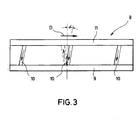
- a fitting roller ring 8 is fitted, which has a circumferential recess 9 on its radially inner upper side in the region of the openings 7, of which extend from a total of three grooves 10 to the end of the opening roller opposite the bearing housing 1 (see also FIGS. 2 and 3).
- a circumferential recess 11 is again provided on the radially inner top side of the opening roller ring 8, which is arranged and formed in mirror image of the recess 9.
- the opening roller ring 8 is held by a cover 12 which is fastened to the base body 4 by means of screws.
- An air inlet opening 13 is provided in the cover 12, which opens into an air collecting space 14 which is formed by the cover 12, the base body 4 and the recess 11 in the opening roller ring 8.
- This air collection space 14 is connected to the cleaning channels formed by the grooves 10.
- the grooves lie in an imaginary jacket plane, the axis of which coincides with the axis of rotation 15 of the opening roller.
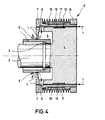
- FIG. 4 shows a second exemplary embodiment of an opening roller unit according to the invention, which is essentially similar is like the embodiment described above, which is why identical reference numerals are used for the same and similar components. In the following only the differences will be discussed.
- the opening roller ring 8 in this exemplary embodiment consists of a support ring 16 and a clothing ring 17 pushed onto its outer circumference.
- the clothing ring 17 is held on the support ring 16 by a pressed-on rim 18.
- the support ring 16 itself is pressed onto the base body 4 and is held there by a circumferential, radially acting spring 19.
- the grooves 10 are arranged on the radially inner upper side of the support ring 16.
- the recess 9 is designed in the form of a radial groove, the groove edge 20 of which faces the end face closes tightly with the front end of the base body 4.
- no recess is provided on the opposite side of the support ring 16, the grooves rather extend continuously to the front end of the opening roller and open into the open there.
- the opening roller rotates in the direction indicated by the arrow D, at relatively high speeds.
- the air in the grooves 10 is therefore pressed in the direction of the arrows L (FIG. 3), with the result that air enters the air collection space 14 through the air inlet 13, through the grooves 10, through the recess 9 and the openings 7 enters the cavity 5.
- an overpressure builds up. This overpressure has the result that a leakage flow to the outside occurs in the annular gap 6, as indicated by the arrows. This leakage flow prevents micro dust, such as is obtained during the spinning of fibers, from entering the cavity 5 through the annular gap 6.
- the excess pressure prevailing in the cavity 5 can be set.
- the grooves 10 in the other direction, d. H. against the direction of rotation D (dashed line in Fig. 3) the air located in the grooves 10 would be moved in the opposite direction, whereby one could achieve that the air located in the cavity 5 would be sucked out and thus a negative pressure would arise there .
- This sucking out would also suck out dust particles located in the cavity 5. It is also conceivable to incline one of the grooves 10 against the direction of rotation and the other grooves in the direction of rotation so that the air would be sucked in through part of the grooves and the air would be blown out through the other groove.
- the exemplary embodiment according to FIG. 4 functions in an analogous manner, where the ambient air gets directly into the inclined grooves 10.
- the advantage of this embodiment is that the support ring 16 can be left on the base body 4 when the clothing ring 17 is to be replaced. Then only the removal of the rim 18 is required.
- the opening roller units on the market with the tension springs 19 have a smaller diameter of the base body 4 than those in which the opening roller rings are held by a cover 12, the opening roller ring 8 from the embodiment according to FIG be used.
- the groove on the radially inner upper side of the opening roller ring in a helical manner. If the pitch of these screws is small enough so that one turn is always above an opening 7, the recess 9, which connects the openings 7 with the grooves 10, can also be omitted.
Landscapes
- Engineering & Computer Science (AREA)
- Mechanical Engineering (AREA)
- Textile Engineering (AREA)
- Spinning Or Twisting Of Yarns (AREA)
Priority Applications (2)
| Application Number | Priority Date | Filing Date | Title |
|---|---|---|---|
| PCT/EP1990/000034 WO1991010762A1 (fr) | 1990-01-08 | 1990-01-08 | Unite de cylindre ouvreur a dents pour machines a filature a fibres liberees |
| EP90100322A EP0436754A1 (fr) | 1990-01-08 | 1990-01-08 | Cylindre peigneur pour une machine de filature à bout libre |
Applications Claiming Priority (1)
| Application Number | Priority Date | Filing Date | Title |
|---|---|---|---|
| EP90100322A EP0436754A1 (fr) | 1990-01-08 | 1990-01-08 | Cylindre peigneur pour une machine de filature à bout libre |
Publications (1)
| Publication Number | Publication Date |
|---|---|
| EP0436754A1 true EP0436754A1 (fr) | 1991-07-17 |
Family
ID=8203470
Family Applications (1)
| Application Number | Title | Priority Date | Filing Date |
|---|---|---|---|
| EP90100322A Withdrawn EP0436754A1 (fr) | 1990-01-08 | 1990-01-08 | Cylindre peigneur pour une machine de filature à bout libre |
Country Status (2)
| Country | Link |
|---|---|
| EP (1) | EP0436754A1 (fr) |
| WO (1) | WO1991010762A1 (fr) |
Cited By (5)
| Publication number | Priority date | Publication date | Assignee | Title |
|---|---|---|---|---|
| DE4124714A1 (de) * | 1991-07-25 | 1993-01-28 | Schmolke Karl Heinz | Aufloesewalzen fuer rotorspinnmaschinen |
| WO1993019232A1 (fr) * | 1992-03-25 | 1993-09-30 | Maschinenfabrik Rieter Ag | Dispositif d'entree separant les impuretes |
| US5794311A (en) * | 1995-06-07 | 1998-08-18 | Rieter Ingolstadt Spinnereimaschinenbau Ag | Opener roller for an open-end spinning device |
| US5867974A (en) * | 1996-11-11 | 1999-02-09 | Spindelfabrick Suessen, Schurr, Stahlecker & Grill Gmbh | Opening device for an open-end spinning machine |
| US5943854A (en) * | 1996-12-20 | 1999-08-31 | Rieter Ingolstadt Spinnereimaschinenbau Ag | Opening rolls for an open end spinning apparatus |
Citations (3)
| Publication number | Priority date | Publication date | Assignee | Title |
|---|---|---|---|---|
| GB2048324A (en) * | 1979-05-01 | 1980-12-10 | Stewart & Sons Hacklemakers | Opening rollers |
| DE8809697U1 (de) * | 1988-07-29 | 1989-11-23 | Hollingsworth Gmbh, 7265 Neubulach | Auflösewalzeneinheit für Offenend-Spinnmaschinen |
| EP0348178A1 (fr) * | 1988-06-22 | 1989-12-27 | WM. R. STEWART & SONS (HACKLEMAKERS) LIMITED | Dispositif de défibrage |
-
1990
- 1990-01-08 EP EP90100322A patent/EP0436754A1/fr not_active Withdrawn
- 1990-01-08 WO PCT/EP1990/000034 patent/WO1991010762A1/fr not_active Ceased
Patent Citations (3)
| Publication number | Priority date | Publication date | Assignee | Title |
|---|---|---|---|---|
| GB2048324A (en) * | 1979-05-01 | 1980-12-10 | Stewart & Sons Hacklemakers | Opening rollers |
| EP0348178A1 (fr) * | 1988-06-22 | 1989-12-27 | WM. R. STEWART & SONS (HACKLEMAKERS) LIMITED | Dispositif de défibrage |
| DE8809697U1 (de) * | 1988-07-29 | 1989-11-23 | Hollingsworth Gmbh, 7265 Neubulach | Auflösewalzeneinheit für Offenend-Spinnmaschinen |
Cited By (7)
| Publication number | Priority date | Publication date | Assignee | Title |
|---|---|---|---|---|
| DE4124714A1 (de) * | 1991-07-25 | 1993-01-28 | Schmolke Karl Heinz | Aufloesewalzen fuer rotorspinnmaschinen |
| WO1993019232A1 (fr) * | 1992-03-25 | 1993-09-30 | Maschinenfabrik Rieter Ag | Dispositif d'entree separant les impuretes |
| US5448800A (en) * | 1992-03-25 | 1995-09-12 | Rieter Machine Works | Trash extractor for separating impurities from a traveling fleece |
| US5794311A (en) * | 1995-06-07 | 1998-08-18 | Rieter Ingolstadt Spinnereimaschinenbau Ag | Opener roller for an open-end spinning device |
| US5899057A (en) * | 1995-06-07 | 1999-05-04 | Rieter Ingolstadt Spinnereimaschinenbau Ag | Opener roller for an open-end spinning device |
| US5867974A (en) * | 1996-11-11 | 1999-02-09 | Spindelfabrick Suessen, Schurr, Stahlecker & Grill Gmbh | Opening device for an open-end spinning machine |
| US5943854A (en) * | 1996-12-20 | 1999-08-31 | Rieter Ingolstadt Spinnereimaschinenbau Ag | Opening rolls for an open end spinning apparatus |
Also Published As
| Publication number | Publication date |
|---|---|
| WO1991010762A1 (fr) | 1991-07-25 |
Similar Documents
| Publication | Publication Date | Title |
|---|---|---|
| DE10302127A1 (de) | Staubentfernungsvorrichtung | |
| DE4404401A1 (de) | Selbstfahrende Erntemaschine | |
| DE2223004A1 (de) | Vorrichtung zum Abfuehren von Foerdergut aus einer pneumatischen Foerdereinrichtung | |
| DE3730980C2 (de) | Mit einer Selbstreinigungseinrichtung ausgestatteter Filterapparat für einen Gasstrom | |
| DE102022134674A1 (de) | Laserrolltrommel und Maschine der Tabak verarbeitenden Industrie | |
| DE19949753A1 (de) | Verfahren und Vorrichtung zur Reinigung einer Oberfläche, insbesondere in einer bedruckstoffverarbeitenden Maschine | |
| DE1939359A1 (de) | Vorrichtung zum Filtrieren von Luft | |
| DE69315518T2 (de) | Vorrichtung und Methode zum Entfernen und Sammeln von Staub und Abfall für eine zweifonturige Strickmaschine | |
| EP0329943A2 (fr) | Meuleuse à disque | |
| DE102016119194A1 (de) | Staubsauger mit einem Filterelement | |
| EP0356795A2 (fr) | Appareil de nettoyage pour les chapeaux marchants de la machine de cardage | |
| DE2748944B2 (de) | Filtervorrichtung | |
| EP0436754A1 (fr) | Cylindre peigneur pour une machine de filature à bout libre | |
| DE2213006A1 (de) | Spindellose Spinnmaschine | |
| DE2129260B2 (de) | Raklierrolle | |
| EP0020516B1 (fr) | Appareil de debourrage des chapeaux d'une machine a carder | |
| EP0640716A2 (fr) | Aménagement pour guider une bande fibreuse dans un séchoir | |
| DE1510590A1 (de) | Vorrichtung zum Absaugen von Faserflug und Fadenabfaellen an Textilmaschinen | |
| DE29703689U1 (de) | Haubenförmige Auffangeinrichtung für eine Bohrkrone o.dgl. zum Auffangen von Bohrmehl | |
| DE2252081B2 (de) | Krempel zur Bearbeitung von Fasermaterial u.dgl., insbesondere Spinngut, mit zumindest einer Tambourwalze | |
| DE4022902A1 (de) | Mahlvorrichtung | |
| DE2458241A1 (de) | Verfahren und vorrichtung zum kardieren von vliesstoffen | |
| DE3235161C2 (de) | Vorrichtung zum Scheren von Stoffbahnen | |
| DE2718389C2 (de) | Luftdrehfilter | |
| EP1493905B1 (fr) | Dispositif de nettoyage pour l'air de refroidissement |
Legal Events
| Date | Code | Title | Description |
|---|---|---|---|
| PUAI | Public reference made under article 153(3) epc to a published international application that has entered the european phase |
Free format text: ORIGINAL CODE: 0009012 |
|
| 17P | Request for examination filed |
Effective date: 19901017 |
|
| AK | Designated contracting states |
Kind code of ref document: A1 Designated state(s): AT BE CH DE ES FR GB GR IT LI NL |
|
| 17Q | First examination report despatched |
Effective date: 19930210 |
|
| STAA | Information on the status of an ep patent application or granted ep patent |
Free format text: STATUS: THE APPLICATION IS DEEMED TO BE WITHDRAWN |
|
| 18D | Application deemed to be withdrawn |
Effective date: 19930621 |