EP0437055B1 - Spiromètre - Google Patents
Spiromètre Download PDFInfo
- Publication number
- EP0437055B1 EP0437055B1 EP90313554A EP90313554A EP0437055B1 EP 0437055 B1 EP0437055 B1 EP 0437055B1 EP 90313554 A EP90313554 A EP 90313554A EP 90313554 A EP90313554 A EP 90313554A EP 0437055 B1 EP0437055 B1 EP 0437055B1
- Authority
- EP
- European Patent Office
- Prior art keywords
- spirometer
- microprocessor
- signal
- electrical signals
- air
- Prior art date
- Legal status (The legal status is an assumption and is not a legal conclusion. Google has not performed a legal analysis and makes no representation as to the accuracy of the status listed.)
- Expired - Lifetime
Links
- 238000012360 testing method Methods 0.000 claims description 7
- 230000004044 response Effects 0.000 claims description 5
- 239000000463 material Substances 0.000 claims description 4
- 239000012535 impurity Substances 0.000 claims description 3
- 239000007788 liquid Substances 0.000 claims description 3
- 239000007789 gas Substances 0.000 claims 1
- 238000005259 measurement Methods 0.000 abstract description 28
- 238000004364 calculation method Methods 0.000 description 5
- 239000012530 fluid Substances 0.000 description 4
- 230000035945 sensitivity Effects 0.000 description 4
- XLYOFNOQVPJJNP-UHFFFAOYSA-N water Substances O XLYOFNOQVPJJNP-UHFFFAOYSA-N 0.000 description 4
- 238000010586 diagram Methods 0.000 description 3
- 230000000694 effects Effects 0.000 description 3
- 230000006870 function Effects 0.000 description 3
- 230000002209 hydrophobic effect Effects 0.000 description 3
- 239000004973 liquid crystal related substance Substances 0.000 description 3
- 238000013459 approach Methods 0.000 description 2
- 238000009530 blood pressure measurement Methods 0.000 description 2
- 239000011248 coating agent Substances 0.000 description 2
- 238000000576 coating method Methods 0.000 description 2
- 238000001514 detection method Methods 0.000 description 2
- 229940079593 drug Drugs 0.000 description 2
- 239000003814 drug Substances 0.000 description 2
- 230000010354 integration Effects 0.000 description 2
- 239000011148 porous material Substances 0.000 description 2
- 210000000115 thoracic cavity Anatomy 0.000 description 2
- 239000004698 Polyethylene Substances 0.000 description 1
- XUIMIQQOPSSXEZ-UHFFFAOYSA-N Silicon Chemical compound [Si] XUIMIQQOPSSXEZ-UHFFFAOYSA-N 0.000 description 1
- 230000003213 activating effect Effects 0.000 description 1
- 230000003044 adaptive effect Effects 0.000 description 1
- 230000002411 adverse Effects 0.000 description 1
- 208000006673 asthma Diseases 0.000 description 1
- 238000006243 chemical reaction Methods 0.000 description 1
- 238000004140 cleaning Methods 0.000 description 1
- 239000013078 crystal Substances 0.000 description 1
- 230000001419 dependent effect Effects 0.000 description 1
- 230000000994 depressogenic effect Effects 0.000 description 1
- 238000013461 design Methods 0.000 description 1
- 238000006073 displacement reaction Methods 0.000 description 1
- 238000013213 extrapolation Methods 0.000 description 1
- 239000004744 fabric Substances 0.000 description 1
- 238000002955 isolation Methods 0.000 description 1
- 210000004072 lung Anatomy 0.000 description 1
- 238000012544 monitoring process Methods 0.000 description 1
- 239000004033 plastic Substances 0.000 description 1
- 229920003023 plastic Polymers 0.000 description 1
- -1 polyethylene Polymers 0.000 description 1
- 229920000573 polyethylene Polymers 0.000 description 1
- 230000000750 progressive effect Effects 0.000 description 1
- 230000002685 pulmonary effect Effects 0.000 description 1
- 230000000241 respiratory effect Effects 0.000 description 1
- 210000003296 saliva Anatomy 0.000 description 1
- 238000005070 sampling Methods 0.000 description 1
- 229910052710 silicon Inorganic materials 0.000 description 1
- 239000010703 silicon Substances 0.000 description 1
- 238000012546 transfer Methods 0.000 description 1
- 230000001052 transient effect Effects 0.000 description 1
- 238000011144 upstream manufacturing Methods 0.000 description 1
Images


Classifications
-
- A—HUMAN NECESSITIES
- A61—MEDICAL OR VETERINARY SCIENCE; HYGIENE
- A61B—DIAGNOSIS; SURGERY; IDENTIFICATION
- A61B5/00—Measuring for diagnostic purposes; Identification of persons
- A61B5/08—Measuring devices for evaluating the respiratory organs
- A61B5/087—Measuring breath flow
-
- A—HUMAN NECESSITIES
- A61—MEDICAL OR VETERINARY SCIENCE; HYGIENE
- A61B—DIAGNOSIS; SURGERY; IDENTIFICATION
- A61B5/00—Measuring for diagnostic purposes; Identification of persons
- A61B5/08—Measuring devices for evaluating the respiratory organs
- A61B5/087—Measuring breath flow
- A61B5/09—Measuring breath flow using an element rotated by the flow
Definitions
- This invention pertains to an apparatus for automatic measure of the volume and flow rate of air exhaled by a person, and more particularly, to a personal spirometer small enough so that it can be carried unobtrusively in a pocket so that person can use it easily with maximum convenience and minimum embarrassment.
- Spirometers are devices used to measure the volume and flow rate of air exhaled by a person. These measurements are important for general physiological studies and for diagnostic analysis of particular patients. For example, the effects of various medicines used to treat patients with pulmonary or asthmatic problems can be best analyzed by monitoring the volume and flow rate of air exhaled at regular intervals before and after the administration of medication.
- spirometers make their measurement by one of two means.
- One type collects the exhaled volume from the subject into a bellows or other container, the displacement of which corresponds to the volume of exhaled air. These devices are by their nature large to allow sufficient air collection volume and hence are not easily made portable.
- a second type measures the rate of air flow through a flow measurement device. Exhaled volume is derived by integration of the air flow rate over some period of time.
- spirometers were rather bulky and expensive devices found mostly in clinics and laboratories. Their operation required a trained technician. Furthermore, most such devices were complicated so that they could not be made small enough to be carried in a pocket.
- pneumotachs such as the Fleisch Pneumotach. These devices depend on a laminar air flow past a resistance element. Such devices need additional means for insuring that the flow remains laminar even at high air velocities. Therefore, these type of devices are inherently complex and relatively large.
- the resistance element frequently includes a screen disposed directly in the air path. This screen intercepts impurities which clog the screen and change the response of the device and in addition are unsanitary.
- the pneumotach also includes pressure measurement ports which frequently become occluded from moisture or impurities, thus adversely altering the accuracy of measurement.
- One form of pneumotach is described in US-A-3 797 479. Attention is also directed to US-A-4 598 700 which describes a portable apparatus including a spirometer which employs a flow-sensing turbine.
- An objective of the present invention is to provide an apparatus which may be used for an accurate and instantaneous measurement of exhaled air.
- a further objective is to provide a self-contained apparatus which can be made small enough to fit in a person's pocket.
- Another objective is to provide an apparatus which is simple enough to be used by the subject and is reliable without special care from the user.
- Yet another objective is to provide an apparatus which can be adapted for data recording.
- the fluid dynamic principles on which the present invention is based are to be found, in part, in Binder, R.C., Fluid Mechanics, 5th Edition, Prentice Hall Inc., Englewood Cliffs, N.J., pgs 236-237.
- This describes a flowmeter comprising a housing including a first section and an air tube attached to said first section, said air tube including a through hole with orifice means for generating turbulence through said tube when air flows therethrough; and pressure sensing means for sensing a pressure differential across said orifice.
- the pressure sensing means includes pipe means extending to said tube and spaced from said orifice means.
- a portable spirometer comprising: a housing including a first section and an air tube attached to said first section, said air tube including a through hole with orifice means for generating turbulence through said tube when air is blown therethrough; pressure sensing means disposed in said housing for sensing a pressure differential across said orifice; circuit means disposed in said housing and coupled to said pressure sensing means for generating electrical signals related to parameters descriptive of said air flow; and memory means for storing said electrical signals; wherein said pressure sensing means includes pipe means extending to said tube and spaced from said orifice means, and transducer means coupled to said pipe means for generating a transducer signal, said circuit means includes amplifier means for amplifying said transducer signal to generate an amplified signal, analog-to-digital converter means for converting said amplified signal into a digital signal and microprocessor means receiving said digital signal for generating said electrical signals, and wherein said pipe means has a non-linear response to air flow and wherein said amplifier
- the spirometer displays two parameters known as FEV1 (the volume of air exhaled in one second in liters) and PEFR (peak expiratory flow rate in liters per second).
- FEV1 the volume of air exhaled in one second in liters
- PEFR peak expiratory flow rate in liters per second
- An adaptive start algorithm is preferably used to detect a true test, using a statistical approach rather than a preset threshold level. More particularly, the device calculates the average and the variance of a window formed of four consecutive samples and flow rate and volume calculations are started only if a progressive increase in the measurements is detected. This approach is found to provide good sensitivity and, at the same time, it is relatively immune to noise.
- the spirometer takes advantage of the non-linear characteristics of the air tube to increase sensitivity without the need for expensive high resolution A/D converters. Separate look-up tables can be used for high and low flow rates to convert pressure differential samples into actual flow rates.
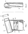
- a personal spirometer 10 constructed in accordance with this invention includes a housing 12 with a generally square section 14 and an air tube 16 disposed on one side of the section 14.
- the spirometer is sized and shaped so that it can fit in a pocket. Furthermore, the spirometer is shaped and sized so that it can be held comfortably in one hand while air is exhaled through it as described more fully below.
- the section 14 has a flat surface 18.
- a control panel 20 is imbedded in surface 18 and it includes a start button 22' and an LCD display screen 24.
- Air tube 16 has an annular mouth piece 26 at one end sized to fit in a person's mouth.
- a cylindrical hole 28 passes through the air tube 16.
- Hole 28 has a substantially constant diameter except at an annular wall 30.
- This annular wall 30 forms a sharp-edged orifice within hole 28.
- Two small openings 32, 34 are spaced on either side of the wall 30 and extend into section 14 for measuring the differential pressure within the air tube due to a flow of exhaled air.
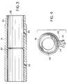
- each of the openings 32, 34 is provided with a plug 36, 36' (only one orifice being shown in Figure 4).
- This plug holds a filter 38 at the interface with hole 28.
- the filter 38 may be made of a porous material which is permeable to air but impermeable to liquids. In this manner, saliva or other materials from the exhaled air of a person will be limited to the tube and will not contaminate the remainder of the spirometer 10. Furthermore since filter 38 is impermeable to water the spirometer may be immersed in or sprayed with water for cleaning and sanitary purposes.
- Filter 38 maybe made for example of a hydrophobic filter media such as a 1.6mm (1/16") thick hydrophobic polyethylene with a 10 micron pore size, and about 40% porosity.
- the plugs are connected by two tubes 40, 42 to a differential pressure transducer 44, which may be for example a MPX 2010D made by Motorola.
- the transducer 44 generates an electrical signal on a pair of output wires 46, which signal is proportional to the differential pressure between tubes 40, 42.
- This signal is amplified by a differential amplifier stage 48 and fed into an analog-to-digital converter 50 which converts the amplifier output into digital signals.
- the converter output is fed to a microprocessor 52.
- the microprocessor 52 uses an algorithm stored in a ROM 54 to perform several calculations on the signal from converter 50, and to display the results (i.e. volume and rate of flow) on display 24.
- Switch 22 activated by button 22' initiates the operation of spirometer 10 through microprocessor 52.
- the results obtained during each measurement may be stored in a RAM 56 for future reference.
- An input/output port 58 may also be provided to allow for changing the programming of the microprocessor. Furthermore the microprocessor may be programmed so that on command it can down-load the results accumulated in RAM 56 through port 58 to a printer or a desk-top computer.
- FIG. 6A and 6B A preferred diagram for implementing the circuit shown in Figure 5 is shown in Figures 6A and 6B. It should be understood that the various circuit elements (such as resistance and capacitance values) are shown in the Figures merely for illustrative purposes and do not limit the scope of this invention in any fashion.
- differential air pressure in the air tube is sensed by the pressure transducer 44 schematically shown as a resistive bridge.
- the output of the transducer is processed by an amplifier analog circuit 48 consisting of amplifiers 60, 62, 64 and 66 which may be, for example, Motorola MC 34074 op amps. These amplifiers are used for a relatively high air flow. For low air flows a further amplifier 68 is also used.
- the outputs of these amplifiers 66, 68 are fed to a multiple channel A/D converter 50, which may be for example a 68HC68A2 manufactured by RCA Harris.
- the A/D converter 50 feeds its output to microprocessor 52 which may be for example a MC68HC804C4 made by Motorola.
- the microprocessor 52 displays the results on the LCD screen 24. (Display screen 24 may also include LCD display drivers not shown in the Figures for the sake of convenience).
- the circuit also includes a power supply 70 which provides the required power to the various circuit elements from a battery 72.
- the operation of the power supply is also controlled by wires W2, W3 by the microprocessor 52. More particularly, the analog section consisting of the amplifiers, the transducer and the digital-to-analog converter is turned on last (when measurements are started) and turned off first (when the measurements are completed) to conserve power.
- the power to the display screen is independently controlled. Preferably, the display is on whenever the microprocessor is on.
- the spirometer 10 further includes a beeper 80 controlled by the microprocessor for generating audible signals for the user.
- a further feature of the invention is an automatic offset compensation circuit consisting of a plurality of resistors 74 and an amplifier 76.
- the resistors 74 are coupled to microprocessor 52 by a plurality of lines 78.
- This offset compensation circuit operates as follows. During the initialization of the spirometer (described more fully below), the microprocessor checks the output of the pressure transducer to insure that it essentially corresponds to no air flow. If the transducer output is non-zero (due for example to a temperature drift, a variation in the output of the power supply 70, the offset voltages of amplifiers 62, 64, 66, 68 and so on) the microprocessor 52 sends a compensating signal through lines 78 to resistors 74.
- Resistors 74 and amplifier 76 cooperate in effect to form a digital-to-analog converter used by the microprocessor 52 to produce a DC offset.
- This DC offset is added by amplifier 62 to the output of transducer 44.
- the microprocessor sequentially changes the signals on lines 78 until the offset signal from amplifier 76 compensates for the error signal from transducer 44.
- the device requires no user adjustment or calibration. To make a measurement, the user pushes the START button 22'. This turns the unit on and initiates a self-test routine. During this self test, all segments on the liquid-crystal display (LCD) are turned on to allow the user to confirm proper operation of the unit. Upon completion of self-test (approximately 5 seconds), the display is blanked except for a READY annunciator: the unit beeps by activity beeper 80 and is now ready for a measurement. The user inhales as much as he can, places his lips around the mouthpiece 26, and blows as hard as possible. The device senses the start of exhalation, measures flow for one second, then displays the volume and maximum rate of air flow for the person (commonly known as FEV1 and PEFR respectively) measurements on display screen 24.
- FEV1 and PEFR commonly known as FEV1 and PEFR respectively
- the parameter FEV1 and the criteria for measuring this parameter is described in the Official Statement of American Thoracic Society, Medical Section of the American Lung Association --Standardization of Spirometry--1987 Update found in Respiratory Care, November '87, Vol. 32, No. 11, pgs. 1039-1060.
- the parameter PEFR is identical to the FEF max parameter in the same Statement.
- the display will persist for 45 seconds, and then the unit will turn itself off, unless the START button 22' is pushed to initiate another measurement cycle. If no breath is detected within 15 seconds of the READY signal, the unit beeps twice and shuts itself off.
- the spirometer 10 determines the flow rate of air by measuring the differences in pressure developed across a restricting orifice. This pressure difference is related to the flow rate by a well-known equation based on Bernoulli's equation for non-compressible flow. (See for instance Binder, R.C., Fluid Mechanics, 5th Edition, Prentice Hall Inc., Englewood Cliffs, N.J., pgs. 236-237.) In the case of the sharp-edged orifice used in this device, the flow rate is equal to a coefficient (found empirically) multiplied by the square-root of the pressure difference measured between a point upstream of the orifice and a point downstream of the orifice.
- the value of the coefficient is predominantly determined by the physical design of the device, including the ratio of the area of the flow tube to the area of the orifice, the size of the orifice, and the location of the pressure measurement ports. Ideally, if these physical parameters were held constant, the pressure difference would be dependent only upon the flow rate and density of the fluid being measured. However, there is also some influence of Reynolds Number upon the value of the coefficient, which introduces an error if the coefficient is treated as a constant over a large range of flows.
- the pressure difference across the orifice is a function of the square of the flow rate. Therefore, an orifice size must be chosen that does not offer excessive back-pressure to the highest flows to be measured, yet has an adequate, measurable pressure difference at low flow rates.
- the air tube 16 contains the sharp-edged orifice (defined by wall 30) that provides a pressure difference which is approximately proportional to the flow rate squared.
- the diameter is about 16mm (5/8") and tube 16 has a diameter of about 22mm (7/8"). This size represents a reasonable compromise between back-pressure at higher flows and at low flows.
- the outside diameter of the tube 16 is approximately 25mm (1") and the length is approximately 89mm (3.5"). Again, the dimensions represent a compromise; an attempt has been made to keep the overall size small enough to fit a pocket or handbag, yet large enough so that an extraneous mouthpiece is unnecessary.
- a tapered profile is provided on the inlet end of the tube so that a disposable mouthpiece may be added (26' in Figure 1) if desired.
- the pressure ports are covered with a disk of hydrophobic filter material (as described above) inset flush with the floor of the tube.
- This material allows air and water vapor to pass freely, but blocks dirt and liquid. It is made of a 1.6mm (1/16") thick rigid plastic and is not easily damaged, allowing the interior of the tube to be cleaned with gently running water or wiped with a soft, lint-free cloth.
- the pressure is transmitted via the 1.6mm (1/16") i.d. pipes 40, 42 to the solid-state, piezo-resistive, differential pressure transducer 44.
- This transducer is provided with a reduced amount of silicon isolation gel coating its diaphragm as compared with the standard transducers used for other measurements. This coating improves the transient response and reduces the sensitivity of the transducer to the position and motion of the spirometer.
- the differential pressure transducer provides an output signal proportional to the pressure difference between the two openings 32, 34.
- the signal from the transducer is amplified and filtered by the 4-stage analog amplifier circuit shown in Figures 6A and 6B. Two outputs are produced by this amplifier circuit.
- the first circuit generated by amplifier 66 has a total gain of 808.
- the second circuit generated by amplifier 68 has a total gain of 3,232.
- the offset voltage of this circuit is adjusted to 300 +/- 50 mV at the first output as described above.
- Two filter stages are included in the analog amplifier circuitry providing a low-pass transfer function with a cut-off frequency of 10hz.
- the first and second outputs from the analog circuitry are fed to two channels marked CH1, CH3 of the 10-bit A/D converter 50.
- a signal proportional to the voltage of battery 72 is fed to channel CH2 on the A/D converter 50.
- the microprocessor controls all aspects of device function. It is able to independently control power to the display, the pressure transducer and analog circuitry, and itself. Timing pulses are provided by a 3.59 MHz crystal 53.
- the microprocessor receives the digital values representing pressure, does all necessary calculations, and generates the codes for the liquid-crystal display circuitry.
- the liquid-crystal display shows the measured values for FEV1 and Peak Expiratory Flow Rate (PEFR). It also includes a BATTERY annunciator to indicate when the battery needs replacement and a READY annunciator to indicate when the device is ready to make a measurement.
- PEFR Peak Expiratory Flow Rate
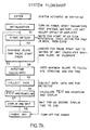
- the microprocessor 52 When the start switch is depressed, the microprocessor 52 is reset and loads its program, which is stored in its Read-Only Memory (ROM) 54. It begins by running a self-test and initialization routine step S1 which checks for internal consistency. It also measures the voltage of battery 72 through input channel CH2 of the A/D converter 52. If the voltage is below a lower limit such that an accurate measurement cannot be made, the microprocessor will not continue. If the voltage is low, but does not exceed this operational limit, the BATTERY annunciator on the LCD is turned on and will not extinguish until the unit turns itself off.
- ROM Read-Only Memory
- the microprocessor then turns on all segments of the display to allow the user to see if any segments are non-functional. Next, it starts sampling the input on channel CH1 of the A/D converter so as to decide which bits of the digital-to-analog converter (I/O lines 78) to turn on or off and to adjust the offset voltage at channel CH1 to 300 +/- 50 mV. This sequence takes about 2 seconds.
- step S2 begins to sample both CH1 and CH3 inputs of the A/D converter signals at a rate of about 100Hz and fills its history array as described below.
- step S2 The subroutines for step S2 are shown in Figures 7B and 7C.
- the unit continues to sample both the CH1 and CH4 channels at 100Hz each. It continuously calculates the average and variance of the past four measurements X1, X2, X3 and X4 from the CH3 channel (Steps S21, 22 and 23). It then compares the next sample (X5) to this average and variance in Steps S24, S26. If the current value is higher than the average by more than 2 standard deviations, the unit branches to a start detection routine (Step 27). If the value is more than 2 volts higher than the average, the microprocessor 52 switches over to the CH1 channel (Step 28) and scales the reading (Step 29).
- the current value is lower than the average or is less than 2 standard deviations higher than the average, the current value becomes the new 4th sample in the average and variance calculation and the loop continues (Steps 22, 30, 39). This loop will continue for a maximum of 15 seconds. If no start is detected (as described below) in this time, the unit will beep twice and turn itself off in step S8.
- Steps 31, 32 the next sample is now checked to see if it is also above a threshold level 128 (Step 32) or the 2 standard deviation threshold (using either the CH3 or CH1 channel, depending on how large the input on channel CH3 is), and also to see if it is higher than the previous sample (Step 33). If both of these conditions are met, a third sample is obtained and checked in the same way (Step 34). (It must be larger than second sample.) If either the second or third sample fails either test, the average and variance are updated using the new sample values and the program returns to the loop above (Steps 35, 36, 37, 38, 39).
- Steps 40, 41, 42, 43 If three samples in a row are larger than the threshold value 128 or the average plus 2 standard deviations, and each is larger than the one preceding it, then start is detected (Steps 40, 41, 42, 43).
- the saved average is stored as the offset to be subtracted from all samples and the 3 samples are converted to flow values and summed as the first three volume increments (Step 41).
- the actual conversion from the measurement pressure differential samples to volumes is accomplished by using two look-up tables stored in ROM 54. One look-up table correlates samples from the low flow channel CH3 (i.e. 0-2 volts) while the second look-up table correlates the samples from the high flow rate channel CH1 (i.e. 0-4 volts). The values on these look-up tables are determined empirically.
- the orifice used to measure flow rate has a non-linear response, i.e. the pressure differential across the openings 32, 34 due to turbulent flow is non-linear.
- the present spirometer takes advantage of this non-lineality by separating the pressure differential samples into two ranges based on the flow rate, and then using a look-up table for each. By switching gains, the microprocessor has expanded resolution at low flows. This would be analogous to an equivalent linear range of 16 volts at 10 bits of resolution, or 4 volts at 12 bits of resolution. This feature is made possible by the non-linear characteristic of the orifice.
- the microprocessor extrapolates between the two closest stored values. Enough samples are stored to keep the extrapolation error small. In this manner, a less-discriminating (having lower resolution) A/D converter can be used without sacrificing accuracy and sensitivity.
- step S3 the unit begins to look for the maximum slope of the volume curve. If the slope determined by several consecutive samples is low or negative, the whole measurement is reported as a false start. The maximum positive slope is determined over seven flow samples and, when found, is back extrapolated to determine the start of the first second timing for FEV1 determination in accordance with the standards set by the American Thoracic Society identified above (step S4). Meantime, each 10 msec. the CH1 and CH3 channels are sampled (step S5). If the CH3 output is less than 2 volts above the offset, it is converted to flow and summed. If the CH3 input is more than 2 volts, the input from channel CH1 is used instead. The unit also looks for, and stores the highest flow sample (step 6).
- the unit displays the measured FEV1 and PEFR (step S7) and it turns off the analog circuitry to save battery life.
- the display is maintained for 45 seconds (or until the START button 22' is pushed to initiate another measurement cycle).
- the microprocessor powers down (step S8) to an idle mode.
- each measurement may be stored into RAM 54 with a time stamp and/or date stamp indicating the time and day on which the measurements were made. The measurements are then recalled and reviewed on the display screen sequentially by activating switch 22. As an incentive, the instantaneous flow measurements could be displayed as the person blows through air tube 26, and when certain mile stones are reached, the beeper could be sounded.
Landscapes
- Health & Medical Sciences (AREA)
- Life Sciences & Earth Sciences (AREA)
- Surgery (AREA)
- Medical Informatics (AREA)
- Pulmonology (AREA)
- Biophysics (AREA)
- Pathology (AREA)
- Engineering & Computer Science (AREA)
- Biomedical Technology (AREA)
- General Health & Medical Sciences (AREA)
- Animal Behavior & Ethology (AREA)
- Molecular Biology (AREA)
- Physics & Mathematics (AREA)
- Physiology (AREA)
- Heart & Thoracic Surgery (AREA)
- Public Health (AREA)
- Veterinary Medicine (AREA)
- Measurement Of The Respiration, Hearing Ability, Form, And Blood Characteristics Of Living Organisms (AREA)
- Investigating Or Analysing Biological Materials (AREA)
- Silicon Polymers (AREA)
- Polyoxymethylene Polymers And Polymers With Carbon-To-Carbon Bonds (AREA)
- Photoreceptors In Electrophotography (AREA)
- Electrochromic Elements, Electrophoresis, Or Variable Reflection Or Absorption Elements (AREA)
- Pens And Brushes (AREA)
- Credit Cards Or The Like (AREA)
Claims (12)
- Spiromètre portable (10), comportant:
un boîtier (12) comprenant une première partie (14) et un tube d'air (16) fixé à ladite première partie, ledit tube d'air comprenant un trou traversant (28) présentant des moyens à orifice (30) pour créer de la turbulence à travers ledit tube lorsque de l'air est soufflé à travers celui-ci; des moyens de détection de pression disposés dans ledit boîtier, pour détecter un différentiel de pression à travers ledit orifice; des moyens à circuit disposés dans ledit boîtier, et couplés auxdits moyens de détection de pression, pour créer des signaux électriques liés à des paramètres descriptifs dudit écoulement d'air; et des moyens à mémoire (56) pour conserver lesdits signaux électriques; dans lequel lesdits moyens de détection de pression comprennent des moyens à tuyau (40, 42) s'étendant vers ledit tube et écartés desdits moyens d'orifice, et des moyens à transducteur (44) couplés auxdits moyens à tuyau pour créer un signal de transducteur, lesdits moyens à circuit comprenant des moyens à amplificateur (48) pour amplifier ledit signal de transducteur en vue de créer un signal amplifié, des moyens à convertisseur analogique-numérique (50) pour transformer ledit signal amplifié en un signal numérique, et des moyens à microprocesseur (52) recevant ledit signal numérique en vue de créer lesdits signaux électriques, et dans lequel lesdits moyens à tuyau (40, 42) présentent une réponse non linéaire à l'écoulement d'air, et dans lequel lesdits moyens à amplificateur (48) créent un premier signal amplifié et un second signal amplifié correspondant respectivement à un débit d'air élevé et à un débit d'air bas, et dans lequel le microprocesseur (52) choisit entre ledit premier et ledit second signal amplifié pour créer lesdits signaux électriques. - Spiromètre selon la revendication 1, comportant en outre des moyens de traitement de signaux en vue d'analyser lesdits signaux électriques.
- Spiromètre selon la revendication 2, dans lequel lesdits moyens de traitement de signaux surveillent une séquence présélectionnée de signaux électriques consécutifs, pour créer des signaux moyens correspondants, et dans lequel lesdits moyens à microprocesseur transforment ledits signaux électriques en signaux de débit.
- Spiromètre selon la revendication 3, dans lequel lesdits moyens à microprocesseur surveillent lesdits signaux moyens pour distinguer un essai à partir d'un bruit.
- Spiromètre selon l'une quelconque des revendications précédentes, comportant en outre des moyens à filtre (36, 36') disposés à l'interface entre lesdits moyens à tuyau (40, 42) et ledit tube (16), pour intercepter des impuretés provenant dudit écoulement d'air.
- Spiromètre selon la revendication 5, dans lequel lesdits moyens à filtre (36, 36') sont réalisés en un matériau perméable aux gaz et imperméable aux liquides.
- Spiromètre selon l'une quelconque des revendications précédentes, comportant en outre des moyens d'alimentation en énergie (70) disposés dans ledit boitier (12), pour alimenter lesdits moyens à circuit en énergie électrique, lesdits moyens à circuit désactivant lesdits moyens d'alimentation en énergie lorsque ledit spiromètre est dans un mode d'attente.
- Spiromètre selon la revendication 7, dans lequel lesdits moyens à circuit électrique comportent des moyens à circuit analogique et des moyens à circuit numérique, et dans lequel lesdits moyens d'alimentation en énergie fournissent de l'énergie auxdits moyens à circuit analogique lorsque ledit spiromètre ne se trouve pas en mode d'attente.
- Spiromètre selon la revendication 7 ou 8, dans lequel lesdits moyens d'alimentation en énergie comprennent une batterie, pour rendre ledit spiromètre autonome.
- Spiromètre selon l'une quelconque des revendications précédentes, comportant en outre des moyens de compensation de décalage en tension, pour décaler les décalages en tension dans lesdits moyens à circuit.
- Spiromètre selon la revendication 10, dans lequel lesdits moyens de compensation de décalage en tension comprennent des moyens à convertisseur numérique-analogique, pour recevoir un signal d'erreur en provenance dudit microprocesseur et correspondant audit décalage en tension, lesdits moyens de convertisseur créant un signal de sortie de convertisseur.
- Spiromètre selon l'une quelconque des revendications précédentes, comportant en outre des moyens d'affichage (24) pour afficher lesdits signaux électriques.
Applications Claiming Priority (2)
| Application Number | Priority Date | Filing Date | Title |
|---|---|---|---|
| US07/461,089 US5137026A (en) | 1990-01-04 | 1990-01-04 | Personal spirometer |
| US461089 | 1990-01-04 |
Publications (2)
| Publication Number | Publication Date |
|---|---|
| EP0437055A1 EP0437055A1 (fr) | 1991-07-17 |
| EP0437055B1 true EP0437055B1 (fr) | 1995-04-12 |
Family
ID=23831180
Family Applications (1)
| Application Number | Title | Priority Date | Filing Date |
|---|---|---|---|
| EP90313554A Expired - Lifetime EP0437055B1 (fr) | 1990-01-04 | 1990-12-13 | Spiromètre |
Country Status (10)
| Country | Link |
|---|---|
| US (1) | US5137026A (fr) |
| EP (1) | EP0437055B1 (fr) |
| JP (1) | JP3102898B2 (fr) |
| AT (1) | ATE120944T1 (fr) |
| AU (1) | AU636183B2 (fr) |
| CA (1) | CA2032796C (fr) |
| DE (1) | DE69018602T2 (fr) |
| DK (1) | DK0437055T3 (fr) |
| ES (1) | ES2073542T3 (fr) |
| NZ (1) | NZ236575A (fr) |
Families Citing this family (124)
| Publication number | Priority date | Publication date | Assignee | Title |
|---|---|---|---|---|
| USD333004S (en) | 1990-03-29 | 1993-02-02 | Ferraris Development And Engineering Company Limited | Ventilatory instrument for measuring peak expiratory flow |
| JPH04330397A (ja) * | 1991-04-30 | 1992-11-18 | Fujitsu Ltd | ターボ分子ポンプ |
| USD339635S (en) | 1991-07-10 | 1993-09-21 | Glaxo Australia Pty., Ltd. | Personal Spirometer |
| DE4203766C1 (en) * | 1992-02-10 | 1993-09-02 | Kolvenbach Kg Elektro-Fluidtechnik, 5100 Aachen, De | Parameter measuring device for physiological and pathological respiration systems - has processor responding to detected pressure and temp values to control mass flow rate for feed and exhaust lines |
| US5277196A (en) * | 1992-03-31 | 1994-01-11 | The United States Of America As Represented By The Department Of Health And Human Services | Portable spirometer with improved accuracy |
| FR2692772B1 (fr) * | 1992-06-24 | 1999-08-27 | Saumur Ateliers Aeronautiques | Spirometre debitmetrique, apte a mesurer la capacite residuelle pulmonaire. |
| US5535633A (en) * | 1992-09-23 | 1996-07-16 | Korr Medical Technologies, Inc. | Differential pressure sensor for respiratory monitoring |
| US5522397A (en) * | 1993-03-10 | 1996-06-04 | Vermaak; Jan C. | Method of and apparatus for monitoring lung function |
| US5373851A (en) * | 1993-04-19 | 1994-12-20 | Brunswick Biomedical Corporation | Specialized peak flow meter |
| US5439430A (en) * | 1993-05-10 | 1995-08-08 | Rubens; Louis C. | Respiratory exerciser |
| US5357972A (en) * | 1993-05-17 | 1994-10-25 | Medical Graphics Corporation | Disposable pneumotachograph flowmeter |
| DE4331451C1 (de) * | 1993-09-16 | 1994-11-17 | Hewlett Packard Gmbh | Blutdruckmeßvorrichtung und Verfahren zum Steuern des Manschettendruckes bei einer Blutdruckmeßvorrichtung |
| US5383470A (en) * | 1993-09-20 | 1995-01-24 | Steve Novak | Portable spirometer |
| EP0646346A3 (fr) * | 1993-09-30 | 1998-06-17 | NDD Medizintechnik GmbH | Dispositif pour mesurer des paramètres des gaz de respiration |
| DK171592B1 (da) * | 1993-12-21 | 1997-02-17 | Maersk Medical As | Anordning for tilførsel af ilt og/eller andre gasser til en patient |
| US5704366A (en) * | 1994-05-23 | 1998-01-06 | Enact Health Management Systems | System for monitoring and reporting medical measurements |
| US5564432A (en) * | 1994-07-13 | 1996-10-15 | Thomson; Ronald A. | Biodegradable air tube and spirometer employing same |
| US5816246A (en) * | 1994-09-15 | 1998-10-06 | Mirza; M. Zubair | Electronic pocket spirometer |
| FR2725123B1 (fr) * | 1994-09-30 | 1996-12-20 | Soc D Thermoformage Et D Injec | Appareil de mesure de debit expiratoire de pointe |
| AUPN332295A0 (en) * | 1995-06-01 | 1995-06-29 | Butler, Donald Lewis | Personal pulmonary function analysers |
| USRE38557E1 (en) | 1995-10-03 | 2004-07-20 | Nt International, Inc. | Non-contaminating pressure transducer module |
| US5693887A (en) | 1995-10-03 | 1997-12-02 | Nt International, Inc. | Pressure sensor module having non-contaminating body and isolation member |
| IL116077A0 (en) * | 1995-11-21 | 1996-01-31 | Tius Elcon Ltd | Electronic spirometer |
| US5839430A (en) * | 1996-04-26 | 1998-11-24 | Cama; Joseph | Combination inhaler and peak flow rate meter |
| US6591695B1 (en) * | 1996-05-07 | 2003-07-15 | Efg & E International | Flow metering device for landfill gas extraction well |
| US5997483A (en) * | 1996-06-21 | 1999-12-07 | Desert Moon Development Limited Partnership | Individualized and calibrated air tube for spirometer |
| US5715831A (en) * | 1996-06-21 | 1998-02-10 | Desert Moon Development Limited Partnership | Calibrated air tube for spirometer |
| US5743270A (en) * | 1996-06-21 | 1998-04-28 | Desert Moon Development Limited Partnership | Resistive element for spirometer |
| EP1003418A4 (fr) | 1996-06-21 | 2000-05-31 | Desert Moon Dev Ltd Partnershi | Element resistif et tube d'air etalonne pour spirometre |
| US5789660A (en) | 1996-07-15 | 1998-08-04 | Novametrix Medical Systems, Inc. | Multiple function airway adapter |
| US7335164B2 (en) | 1996-07-15 | 2008-02-26 | Ntc Technology, Inc. | Multiple function airway adapter |
| US6168568B1 (en) * | 1996-10-04 | 2001-01-02 | Karmel Medical Acoustic Technologies Ltd. | Phonopneumograph system |
| AUPO511397A0 (en) | 1997-02-14 | 1997-04-11 | Resmed Limited | An apparatus for varying the flow area of a conduit |
| US6098463A (en) * | 1997-02-18 | 2000-08-08 | Etymotic Research, Inc. | Method and apparatus for measurement of wide dynamic range signals |
| US5881723A (en) | 1997-03-14 | 1999-03-16 | Nellcor Puritan Bennett Incorporated | Ventilator breath display and graphic user interface |
| AUPO742297A0 (en) | 1997-06-18 | 1997-07-10 | Resmed Limited | An apparatus for supplying breathable gas |
| US6017315A (en) * | 1998-02-25 | 2000-01-25 | Respironics, Inc. | Patient monitor and method of using same |
| US20050121033A1 (en) * | 1998-02-25 | 2005-06-09 | Ric Investments, Llc. | Respiratory monitoring during gas delivery |
| US6544192B2 (en) | 1998-02-25 | 2003-04-08 | Respironics, Inc. | Patient monitor and method of using same |
| WO1999046835A1 (fr) | 1998-03-11 | 1999-09-16 | Nikon Corporation | Dispositif a laser ultraviolet et appareil d'exposition comportant un tel dispositif a laser ultraviolet |
| IL124901A0 (en) * | 1998-06-14 | 1999-01-26 | Tapuz Med Tech Ltd | Lung function measuring device |
| US6062208A (en) * | 1999-01-11 | 2000-05-16 | Seefeldt; William J. | Paintball gun monitor |
| US6474325B2 (en) * | 1999-01-22 | 2002-11-05 | Npf Limited | Gas regulator |
| US6367475B1 (en) | 1999-04-02 | 2002-04-09 | Korr Medical Technologies, Inc. | Respiratory flow meter and methods of use |
| US6581596B1 (en) * | 1999-09-24 | 2003-06-24 | Respironics, Inc. | Apparatus and method of providing high frequency variable pressure to a patient |
| DE19950237A1 (de) * | 1999-10-19 | 2001-06-13 | Glukomeditech Ag | Vorrichtung zur Erfassung des respiratorischen Nasenstroms |
| AU4709501A (en) * | 1999-11-30 | 2001-06-18 | Qrs Diagnostic, Llc | Slant fabric spirometer design |
| US6447459B1 (en) | 2000-04-07 | 2002-09-10 | Pds Healthcare Products, Inc. | Device and method for measuring lung performance |
| AU2001296456A1 (en) | 2000-09-29 | 2002-04-08 | Healthetech, Inc. | Indirect calorimetry system |
| ES2188405B1 (es) * | 2001-10-22 | 2005-02-01 | Servicio De Instrumentacion Hospitalaria, S.L. | Espirometro portatil de pico. |
| WO2004049940A1 (fr) * | 2001-10-22 | 2004-06-17 | Servicio De Instrumentacion Hospitalaria, S.L. | Dispositif de mesure du debit expiratoire de pointe portatif |
| US7291115B2 (en) * | 2001-11-05 | 2007-11-06 | Health Solutions, S.L. | Spirometer and method to measure the ventilatory function by spirometry |
| US7094208B2 (en) | 2002-04-03 | 2006-08-22 | Illinois Institute Of Technology | Spirometer |
| US20060100537A1 (en) * | 2002-04-03 | 2006-05-11 | Williams David R | Spirometer |
| US6915705B1 (en) | 2002-04-03 | 2005-07-12 | Ric Investments, Inc. | Flow sensor and flow resistive element |
| CA2386639A1 (fr) * | 2002-05-16 | 2003-11-16 | Dynamic Mt Gmbh | Spirometre electronique portatif |
| US6733464B2 (en) | 2002-08-23 | 2004-05-11 | Hewlett-Packard Development Company, L.P. | Multi-function sensor device and methods for its use |
| GB2397738B (en) † | 2003-01-21 | 2007-08-29 | Elekta Ab | Computed tomography scanning |
| DE10316333B3 (de) * | 2003-04-10 | 2004-01-22 | Dräger Safety AG & Co. KGaA | Atemalkohol-Messgerät mit verbessertem Mundstück |
| US7749169B2 (en) * | 2003-04-10 | 2010-07-06 | Intoximeters, Inc. | Handheld breath tester housing and mouthpiece |
| US7282032B2 (en) * | 2003-06-03 | 2007-10-16 | Miller Thomas P | Portable respiratory diagnostic device |
| US7063304B2 (en) * | 2003-07-11 | 2006-06-20 | Entegris, Inc. | Extended stroke valve and diaphragm |
| TWI220540B (en) * | 2003-07-18 | 2004-08-21 | Au Optronics Corp | Buffer of pressure gauge sensor used in dry etching reaction chamber |
| US7172557B1 (en) * | 2003-08-29 | 2007-02-06 | Caldyne, Inc. | Spirometer, display and method |
| US7383740B2 (en) * | 2003-11-17 | 2008-06-10 | Spirojet Medical Ltd | Spirometer |
| WO2005051177A2 (fr) * | 2003-11-25 | 2005-06-09 | Coifman Robert E | Dispositifs de mesure du flux d'air inspire |
| EP1761742A1 (fr) * | 2004-06-28 | 2007-03-14 | Inogen, Inc. | Conception d'un appareil d'economie destinee a un systeme de melange respiratoire therapeutique |
| US7625345B2 (en) * | 2005-03-14 | 2009-12-01 | Welch Allyn, Inc. | Motivational spirometry system and method |
| US8034002B2 (en) * | 2005-03-17 | 2011-10-11 | Coifman Robert E | Apparatus and method for intelligent electronic peak flow meters |
| US20060217625A1 (en) * | 2005-03-25 | 2006-09-28 | Forrester Macquorn R Jr | Mouthpiece for breath tester |
| US7656301B2 (en) * | 2005-12-14 | 2010-02-02 | Teradata Us, Inc. | Smoke detection for hardware cabinets |
| US8460223B2 (en) | 2006-03-15 | 2013-06-11 | Hill-Rom Services Pte. Ltd. | High frequency chest wall oscillation system |
| US8021310B2 (en) | 2006-04-21 | 2011-09-20 | Nellcor Puritan Bennett Llc | Work of breathing display for a ventilation system |
| EP2063945B1 (fr) | 2006-09-07 | 2019-07-03 | ResMed Ltd. | Masque et système générateur de flux |
| US7784461B2 (en) | 2006-09-26 | 2010-08-31 | Nellcor Puritan Bennett Llc | Three-dimensional waveform display for a breathing assistance system |
| US7987615B2 (en) * | 2006-11-08 | 2011-08-02 | Lg Electronics Inc. | Exhaust structure for clothes dryer in apartment building |
| TWI322681B (en) * | 2007-05-25 | 2010-04-01 | Health gaming device and method of using such device | |
| US8479733B2 (en) * | 2009-01-27 | 2013-07-09 | General Electric Company | System and method for a flow sensor |
| US10330513B2 (en) * | 2009-05-27 | 2019-06-25 | Honeywell International Inc. | Multi-dynamic-range sensor |
| IN2012DN02116A (fr) * | 2009-08-13 | 2015-08-21 | Lungtek Ltd | |
| US9119925B2 (en) | 2009-12-04 | 2015-09-01 | Covidien Lp | Quick initiation of respiratory support via a ventilator user interface |
| US8335992B2 (en) | 2009-12-04 | 2012-12-18 | Nellcor Puritan Bennett Llc | Visual indication of settings changes on a ventilator graphical user interface |
| US8924878B2 (en) | 2009-12-04 | 2014-12-30 | Covidien Lp | Display and access to settings on a ventilator graphical user interface |
| US8499252B2 (en) | 2009-12-18 | 2013-07-30 | Covidien Lp | Display of respiratory data graphs on a ventilator graphical user interface |
| US9262588B2 (en) | 2009-12-18 | 2016-02-16 | Covidien Lp | Display of respiratory data graphs on a ventilator graphical user interface |
| US8656772B2 (en) | 2010-03-22 | 2014-02-25 | Honeywell International Inc. | Flow sensor with pressure output signal |
| US8113046B2 (en) | 2010-03-22 | 2012-02-14 | Honeywell International Inc. | Sensor assembly with hydrophobic filter |
| USD693468S1 (en) * | 2010-07-28 | 2013-11-12 | Pmd Healthcare | Personal spirometer |
| USD666097S1 (en) | 2010-11-01 | 2012-08-28 | Colgate-Palmolive Company | Cap for a container |
| USD666098S1 (en) | 2010-11-01 | 2012-08-28 | Colgate-Palmolive Company | Cap for a container |
| USD666492S1 (en) | 2010-11-01 | 2012-09-04 | Colgate-Palmolive Company | Cap for a container |
| USD666099S1 (en) | 2010-11-01 | 2012-08-28 | Colgate-Palmolive Company | Cap for a container |
| USD666493S1 (en) | 2010-11-01 | 2012-09-04 | Colgate-Palmolive Company | Cap for a container |
| USD666096S1 (en) | 2010-11-01 | 2012-08-28 | Colgate-Palmolive Company | Cap for a container |
| US8695417B2 (en) | 2011-01-31 | 2014-04-15 | Honeywell International Inc. | Flow sensor with enhanced flow range capability |
| US10271767B2 (en) * | 2011-01-31 | 2019-04-30 | Koninklijke Philips N.V. | Automated spirogram analysis and interpretation |
| USD659835S1 (en) * | 2011-04-04 | 2012-05-15 | Benson Medical Instruments Company | Spirometer airway |
| FR2977470A1 (fr) | 2011-07-08 | 2013-01-11 | Air Liquide Medical Systems | Systeme de mesure de pression pour ventilateur medical |
| MX2014015337A (es) * | 2012-06-13 | 2015-03-05 | Univ California | Dispositivo personal de monitoreo de funcion pulmonar capaz de un analisis de aliento exhalado. |
| FR2992845B1 (fr) * | 2012-07-05 | 2015-05-08 | Isp System | Dispositif de mesure d'un flux gazeux pour l'imagerie medicale |
| US10362967B2 (en) | 2012-07-09 | 2019-07-30 | Covidien Lp | Systems and methods for missed breath detection and indication |
| US9052217B2 (en) | 2012-11-09 | 2015-06-09 | Honeywell International Inc. | Variable scale sensor |
| GB2512047B (en) * | 2013-03-15 | 2015-07-15 | Univ Sheffield Hallam | Positive Expiratory Pressure Device With Electronic Monitoring |
| WO2014146714A1 (fr) | 2013-03-21 | 2014-09-25 | Barbetta Marco | Procédé et appareil pour la détection de la concentration d'alcool dans l'haleine faisant appel à un échantillonneur acoustique d'haleine |
| US10893825B2 (en) | 2014-01-31 | 2021-01-19 | North Carolina State University | System and method of monitoring respiratory parameters |
| US9950129B2 (en) | 2014-10-27 | 2018-04-24 | Covidien Lp | Ventilation triggering using change-point detection |
| CN104586396B (zh) * | 2014-12-12 | 2017-04-26 | 歌尔股份有限公司 | 一种肺活量的测试方法和设备 |
| KR101808691B1 (ko) * | 2015-06-25 | 2017-12-14 | 충북대학교 산학협력단 | 중환자 호흡 모니터링 시스템 및 방법 |
| US11433211B2 (en) | 2016-03-17 | 2022-09-06 | Zoll Medical Corporation | Flow sensor for ventilation |
| CN105865545B (zh) * | 2016-05-30 | 2019-04-02 | 贵州大学 | 一种双探头差压流量传感器及其检测方法 |
| CN106092218B (zh) * | 2016-05-30 | 2019-02-12 | 贵州大学 | 一种双探头差压流量传感器探头及其检测方法 |
| CN105865544B (zh) * | 2016-05-30 | 2019-03-12 | 贵州大学 | 双活塞对称阻尼式流量传感器及其检测方法 |
| EP4008251A1 (fr) | 2016-09-06 | 2022-06-08 | Vigor Medical Systems, Inc. | Système numérique de programme de traitement ou de réhabilitation |
| WO2018061022A1 (fr) | 2016-09-28 | 2018-04-05 | Indian Institute Of Technology, Guwahati | Dispositif de surveillance d'état pulmonaire |
| JP2020500049A (ja) | 2016-10-20 | 2020-01-09 | ヘルスアップ エスピー.ゼット オー.オー.Healthup Sp. Z O.O. | 携帯型肺活量計 |
| USD848620S1 (en) * | 2016-11-28 | 2019-05-14 | Spirosure, Inc. | Mouthpiece for a respiratory monitor |
| USD833014S1 (en) * | 2017-01-25 | 2018-11-06 | Healthup Sp. z.o.o. | Portable spirometer |
| EP3781028B1 (fr) * | 2018-04-19 | 2024-07-10 | Healthup S.A. | Spiromètre électronique portatif |
| KR102039984B1 (ko) * | 2019-05-10 | 2019-11-04 | 브레싱스 주식회사 | 호흡 측정 장치 |
| US11672934B2 (en) | 2020-05-12 | 2023-06-13 | Covidien Lp | Remote ventilator adjustment |
| USD1060658S1 (en) | 2020-12-28 | 2025-02-04 | ResMed Asia Pte. Ltd. | Patient interface |
| JP2024530383A (ja) * | 2021-08-11 | 2024-08-21 | カリフォルニア インスティチュート オブ テクノロジー | 非侵襲的脈圧波形測定のためのシステム及び方法 |
| USD1021096S1 (en) * | 2022-05-06 | 2024-04-02 | Ulrich Gmbh & Co. Kg | Spirometer for medical purposes |
| JPWO2024202812A1 (fr) * | 2023-03-27 | 2024-10-03 |
Citations (1)
| Publication number | Priority date | Publication date | Assignee | Title |
|---|---|---|---|---|
| WO1989012423A1 (fr) * | 1988-06-17 | 1989-12-28 | Adx Systems Pty Limited | Systeme de surveillance |
Family Cites Families (57)
| Publication number | Priority date | Publication date | Assignee | Title |
|---|---|---|---|---|
| US3433217A (en) * | 1965-09-30 | 1969-03-18 | Gen Electric | Respiration monitor |
| US3577984A (en) * | 1967-03-27 | 1971-05-11 | Donti Research Dev Mfg | Spirometer |
| US3504542A (en) * | 1967-08-21 | 1970-04-07 | Us Army | Air flowmeter |
| GB1160669A (en) * | 1968-07-04 | 1969-08-06 | Ferraris Dev & Eng Co Ltd | Improvements in or relating to Detent Devices |
| US3621835A (en) * | 1968-07-08 | 1971-11-23 | Takaji Suzuki | Apparatus for automatically testing pulmonary functions |
| US3606883A (en) * | 1969-02-03 | 1971-09-21 | Sutter Hosp Medical Res | Spirometer with normalizing means |
| US3608546A (en) * | 1970-01-21 | 1971-09-28 | Gen Electric | Fluidic spirometer |
| US3626755A (en) * | 1970-04-09 | 1971-12-14 | Hans Rudolph Inc | Flow measuring apparatus |
| US3645133A (en) * | 1970-04-15 | 1972-02-29 | Metrophysics Inc | Electronic spirometer |
| GB1351112A (en) * | 1970-05-29 | 1974-04-24 | Ferraris Dev Eng Co Ltd | Apparatus for indicating the rate of fluid flow |
| US3635214A (en) * | 1970-07-29 | 1972-01-18 | William A Rand | Visual pulmonary meter |
| US3722506A (en) * | 1970-10-15 | 1973-03-27 | Airco Inc | Rolling seal spirometer |
| US3703893A (en) * | 1970-10-23 | 1972-11-28 | Spearhead Inc | Method and apparatus for determining work of breathing |
| US3713337A (en) * | 1971-02-04 | 1973-01-30 | Daniel Ind Inc | Apparatus and method for automatic differential pressure transducer range changing |
| US3720202A (en) * | 1971-10-05 | 1973-03-13 | J Cleary | Instrument for measuring maximum expiratory flow rate |
| US3822699A (en) * | 1971-10-05 | 1974-07-09 | J Cleary | Instrument for measuring maximum expiratory flow rate |
| GB1385037A (en) * | 1972-02-19 | 1975-02-26 | Wilkinson Sword Ltd | Spirometers |
| US3818901A (en) * | 1972-04-12 | 1974-06-25 | Del Mar Eng Lab | Apparatus for automatically periodically measuring and displaying the total air expired by a subject during each of a succession of given time intervals |
| US3797479A (en) * | 1972-04-14 | 1974-03-19 | Comprehensive Health Testing L | Spirometer |
| US3862628A (en) * | 1972-05-02 | 1975-01-28 | Ferraris Dev & Eng Co Ltd | Peak flow meters |
| US3826247A (en) * | 1972-06-27 | 1974-07-30 | A Ruskin | Pulmonary achievement trainer |
| US3810461A (en) * | 1972-09-11 | 1974-05-14 | American Health Inc | Disposable pulmonary function kit |
| SE370178B (fr) * | 1973-01-29 | 1974-10-07 | Lkb Medical Ab | |
| GB1463814A (en) * | 1973-07-17 | 1977-02-09 | Nat Res Dev | Ventilatory capacity measurement instruments |
| US3871364A (en) * | 1973-09-24 | 1975-03-18 | John Randall Boehringer | Peak flow meter-expiratory flow rate |
| US3946726A (en) * | 1974-08-07 | 1976-03-30 | Puriton-Bennett Corporation | Pulmonary diagnostic instrument including breath transducer |
| US3960142A (en) * | 1974-12-02 | 1976-06-01 | The Institutes Of Medical Sciences | Air flow to pressure differential transducer for pneumotachography |
| CH607913A5 (fr) * | 1975-07-08 | 1978-12-15 | Siemens Ag | |
| US4034743A (en) * | 1975-10-24 | 1977-07-12 | Airco, Inc. | Automated pulmonary function testing apparatus |
| US4047521A (en) * | 1975-11-04 | 1977-09-13 | Carl Kramer | Rate-of-flow meter, particularly for diagnostic spirometry |
| DE2622117B1 (de) * | 1976-05-18 | 1977-09-15 | Siemens Ag | Stroemungsmesser |
| GB1576118A (en) * | 1976-06-02 | 1980-10-01 | Boc Ltd | Lung ventilators |
| US4202353A (en) * | 1977-02-22 | 1980-05-13 | United States Surgical Corporation | Temperature and respiration sensing probe |
| US4158360A (en) * | 1978-01-26 | 1979-06-19 | Projects In Health, Inc. | Expiratory flow meter |
| US4182347A (en) * | 1978-02-27 | 1980-01-08 | Russo Ronald D | Air inhalation flow rate measuring device |
| US4267845A (en) * | 1978-10-05 | 1981-05-19 | Robertson Jr Charles H | Method and apparatus for measuring pulmonary ventilation |
| US4241739A (en) * | 1978-11-13 | 1980-12-30 | C. R. Bard, Inc. | Volume calculator for incentive spirometer |
| DE2941426A1 (de) * | 1979-07-20 | 1981-02-05 | Gerhard Prof Dr Ing Mueller | Anwendung eines fluidstroemungsmessers |
| DE2933116A1 (de) * | 1979-08-16 | 1981-02-26 | Rico Ges Fuer Microelektronik | Einrichtung zur messung des atemluftstromes von patienten |
| US4406291A (en) * | 1980-04-07 | 1983-09-27 | Schwesinger Dennis W | Exhalation monitoring apparatus |
| US4403514A (en) * | 1980-05-20 | 1983-09-13 | Critikon, Inc. | Pneumotachograph with pitot-like tubes |
| DE3023648A1 (de) * | 1980-06-24 | 1982-01-21 | Jaeger, Erich, 8700 Würzburg | Einrichtung zur untersuchung der atemwege auf reizstoff-ueberempfindlichkeit |
| JPS5948106B2 (ja) * | 1980-08-27 | 1984-11-24 | 株式会社東芝 | 呼吸監視装置 |
| US4407295A (en) * | 1980-10-16 | 1983-10-04 | Dna Medical, Inc. | Miniature physiological monitor with interchangeable sensors |
| JPS5777914A (en) * | 1980-10-31 | 1982-05-15 | Toshiba Corp | Fluid measuring apparatus |
| US4421120A (en) * | 1981-03-02 | 1983-12-20 | Biotrine Corporation | Peak respiratory flow monitor |
| US4736750A (en) * | 1981-04-24 | 1988-04-12 | Valdespino Joseph M | Apparatus for testing pulmonary functions |
| US4768520A (en) * | 1981-05-06 | 1988-09-06 | Varraux Alan R | Peak flow and pulmonary incentive meter |
| US4807641A (en) * | 1982-08-27 | 1989-02-28 | Boehringer Laboratories | Pneumotach and components therefore and combined pulmonary function measuring kit containing the same |
| GB2133157B (en) * | 1982-10-09 | 1986-02-19 | Richard Bernhard Richardson | Electronic lung function analyser |
| SE8206211L (sv) * | 1982-11-02 | 1984-05-03 | Karolinska Inst Med Tek | Anordning for metning av dubbelriktade andningsfloden, utan att utoka det skadliga rummet |
| JPS60500653A (ja) * | 1983-01-04 | 1985-05-09 | エテ−レ・ヘメ−ン・カウ−コバマイ−デイステイス・ア−ル・ワイ | 吐息量メ−タ |
| US4495944A (en) * | 1983-02-07 | 1985-01-29 | Trutek Research, Inc. | Inhalation therapy apparatus |
| US4598700A (en) * | 1983-03-14 | 1986-07-08 | Tamm Ulf S | Apparatus for measuring pulse rate and pulmonary volume |
| DE3322536A1 (de) * | 1983-06-23 | 1985-01-10 | Ganshorn Electronic GmbH, 8732 Münnerstadt | Exspirationsluft-aufnahmegefaess sowie dessen verwendung zur messung der lungenfunktion |
| US4644958A (en) * | 1984-03-26 | 1987-02-24 | Trutek Research, Inc. | Inhalation therapy apparatus adapter |
| US4796639A (en) * | 1987-11-05 | 1989-01-10 | Medical Graphics Corporation | Pulmonary diagnostic system |
-
1990
- 1990-01-04 US US07/461,089 patent/US5137026A/en not_active Expired - Lifetime
- 1990-12-12 AU AU67994/90A patent/AU636183B2/en not_active Ceased
- 1990-12-13 DE DE69018602T patent/DE69018602T2/de not_active Expired - Fee Related
- 1990-12-13 ES ES90313554T patent/ES2073542T3/es not_active Expired - Lifetime
- 1990-12-13 DK DK90313554.9T patent/DK0437055T3/da active
- 1990-12-13 EP EP90313554A patent/EP0437055B1/fr not_active Expired - Lifetime
- 1990-12-13 AT AT90313554T patent/ATE120944T1/de not_active IP Right Cessation
- 1990-12-20 CA CA002032796A patent/CA2032796C/fr not_active Expired - Fee Related
- 1990-12-20 NZ NZ236575A patent/NZ236575A/en unknown
- 1990-12-27 JP JP02408252A patent/JP3102898B2/ja not_active Expired - Fee Related
Patent Citations (1)
| Publication number | Priority date | Publication date | Assignee | Title |
|---|---|---|---|---|
| WO1989012423A1 (fr) * | 1988-06-17 | 1989-12-28 | Adx Systems Pty Limited | Systeme de surveillance |
Non-Patent Citations (1)
| Title |
|---|
| Binder, R.C.: "Fluid Mechanics", 5th edition, Prentice Hall, Englewood Cliffs, N.J., pgs. 236-237 (1973); * |
Also Published As
| Publication number | Publication date |
|---|---|
| CA2032796C (fr) | 2000-12-05 |
| DK0437055T3 (da) | 1995-07-10 |
| DE69018602T2 (de) | 1995-10-26 |
| ES2073542T3 (es) | 1995-08-16 |
| JPH0428350A (ja) | 1992-01-30 |
| EP0437055A1 (fr) | 1991-07-17 |
| US5137026A (en) | 1992-08-11 |
| AU6799490A (en) | 1991-07-11 |
| JP3102898B2 (ja) | 2000-10-23 |
| ATE120944T1 (de) | 1995-04-15 |
| CA2032796A1 (fr) | 1991-07-05 |
| DE69018602D1 (de) | 1995-05-18 |
| NZ236575A (en) | 1994-01-26 |
| AU636183B2 (en) | 1993-04-22 |
Similar Documents
| Publication | Publication Date | Title |
|---|---|---|
| EP0437055B1 (fr) | Spiromètre | |
| US5373851A (en) | Specialized peak flow meter | |
| US20030216659A1 (en) | Portable electronic spirometer | |
| JP3468574B2 (ja) | 被検者の肺機能をモニターする装置 | |
| US6849049B2 (en) | Patient monitor and method of using same | |
| US6066101A (en) | Airflow perturbation device and method for measuring respiratory resistance | |
| US4630614A (en) | Apnea monitoring apparatus | |
| US5562101A (en) | Portable spirometer with improved accuracy | |
| US7094208B2 (en) | Spirometer | |
| US5058601A (en) | Pulmonary function tester | |
| JP2568763B2 (ja) | 気体流量測定システム | |
| AU778731B2 (en) | Biological information collecting device comprising closed pneumatic sound sensor | |
| US5170798A (en) | Pulmonary function tester | |
| KR101132595B1 (ko) | 휴대형 폐활량계 | |
| WO2002071017A2 (fr) | Systeme et procede de mesure de vitesse de metabolisme | |
| GB2576137A (en) | Multi-test respiratory diagnostic device | |
| US20060100537A1 (en) | Spirometer | |
| JP2740234B2 (ja) | 肺機能テスタ | |
| EP4584558B1 (fr) | Tube de pitot pour la mesure de débits respiratoires élevés et faibles | |
| GB2267758A (en) | Airflow measuring device | |
| RU45911U1 (ru) | Пневмотахограф | |
| JP2001218744A (ja) | 生体活動測定装置 | |
| GB2576136A (en) | Multi-test respiratory diagnostic device |
Legal Events
| Date | Code | Title | Description |
|---|---|---|---|
| PUAI | Public reference made under article 153(3) epc to a published international application that has entered the european phase |
Free format text: ORIGINAL CODE: 0009012 |
|
| AK | Designated contracting states |
Kind code of ref document: A1 Designated state(s): AT BE CH DE DK ES FR GB GR IT LI LU NL SE |
|
| 17P | Request for examination filed |
Effective date: 19910815 |
|
| 17Q | First examination report despatched |
Effective date: 19940405 |
|
| GRAA | (expected) grant |
Free format text: ORIGINAL CODE: 0009210 |
|
| AK | Designated contracting states |
Kind code of ref document: B1 Designated state(s): AT BE CH DE DK ES FR GB GR IT LI LU NL SE |
|
| REF | Corresponds to: |
Ref document number: 120944 Country of ref document: AT Date of ref document: 19950415 Kind code of ref document: T |
|
| REF | Corresponds to: |
Ref document number: 69018602 Country of ref document: DE Date of ref document: 19950518 |
|
| ET | Fr: translation filed | ||
| ITF | It: translation for a ep patent filed | ||
| REG | Reference to a national code |
Ref country code: DK Ref legal event code: T3 |
|
| REG | Reference to a national code |
Ref country code: ES Ref legal event code: FG2A Ref document number: 2073542 Country of ref document: ES Kind code of ref document: T3 |
|
| REG | Reference to a national code |
Ref country code: GR Ref legal event code: FG4A Free format text: 3016734 |
|
| PLBE | No opposition filed within time limit |
Free format text: ORIGINAL CODE: 0009261 |
|
| STAA | Information on the status of an ep patent application or granted ep patent |
Free format text: STATUS: NO OPPOSITION FILED WITHIN TIME LIMIT |
|
| 26N | No opposition filed | ||
| REG | Reference to a national code |
Ref country code: CH Ref legal event code: PFA Free format text: GLAXO AUSTRALIA PTY, LTD TRANSFER- GLAXO WELLCOME AUSTRALIA LTD. |
|
| REG | Reference to a national code |
Ref country code: FR Ref legal event code: CD |
|
| NLT1 | Nl: modifications of names registered in virtue of documents presented to the patent office pursuant to art. 16 a, paragraph 1 |
Owner name: GLAXO WELLCOME AUSTRALIA LTD |
|
| REG | Reference to a national code |
Ref country code: ES Ref legal event code: PC2A |
|
| REG | Reference to a national code |
Ref country code: GB Ref legal event code: IF02 |
|
| PGFP | Annual fee paid to national office [announced via postgrant information from national office to epo] |
Ref country code: GB Payment date: 20031217 Year of fee payment: 14 |
|
| PGFP | Annual fee paid to national office [announced via postgrant information from national office to epo] |
Ref country code: FR Payment date: 20031223 Year of fee payment: 14 |
|
| PGFP | Annual fee paid to national office [announced via postgrant information from national office to epo] |
Ref country code: SE Payment date: 20031229 Year of fee payment: 14 Ref country code: NL Payment date: 20031229 Year of fee payment: 14 Ref country code: DE Payment date: 20031229 Year of fee payment: 14 Ref country code: AT Payment date: 20031229 Year of fee payment: 14 |
|
| PGFP | Annual fee paid to national office [announced via postgrant information from national office to epo] |
Ref country code: LU Payment date: 20031230 Year of fee payment: 14 |
|
| PGFP | Annual fee paid to national office [announced via postgrant information from national office to epo] |
Ref country code: GR Payment date: 20031231 Year of fee payment: 14 |
|
| PGFP | Annual fee paid to national office [announced via postgrant information from national office to epo] |
Ref country code: DK Payment date: 20040102 Year of fee payment: 14 |
|
| PGFP | Annual fee paid to national office [announced via postgrant information from national office to epo] |
Ref country code: CH Payment date: 20040105 Year of fee payment: 14 |
|
| PGFP | Annual fee paid to national office [announced via postgrant information from national office to epo] |
Ref country code: ES Payment date: 20040123 Year of fee payment: 14 |
|
| PGFP | Annual fee paid to national office [announced via postgrant information from national office to epo] |
Ref country code: BE Payment date: 20040212 Year of fee payment: 14 |
|
| PG25 | Lapsed in a contracting state [announced via postgrant information from national office to epo] |
Ref country code: LU Free format text: LAPSE BECAUSE OF NON-PAYMENT OF DUE FEES Effective date: 20041213 Ref country code: GB Free format text: LAPSE BECAUSE OF NON-PAYMENT OF DUE FEES Effective date: 20041213 Ref country code: AT Free format text: LAPSE BECAUSE OF NON-PAYMENT OF DUE FEES Effective date: 20041213 |
|
| PG25 | Lapsed in a contracting state [announced via postgrant information from national office to epo] |
Ref country code: SE Free format text: LAPSE BECAUSE OF NON-PAYMENT OF DUE FEES Effective date: 20041214 Ref country code: ES Free format text: LAPSE BECAUSE OF NON-PAYMENT OF DUE FEES Effective date: 20041214 |
|
| PG25 | Lapsed in a contracting state [announced via postgrant information from national office to epo] |
Ref country code: LI Free format text: LAPSE BECAUSE OF NON-PAYMENT OF DUE FEES Effective date: 20041231 Ref country code: CH Free format text: LAPSE BECAUSE OF NON-PAYMENT OF DUE FEES Effective date: 20041231 Ref country code: BE Free format text: LAPSE BECAUSE OF NON-PAYMENT OF DUE FEES Effective date: 20041231 |
|
| PG25 | Lapsed in a contracting state [announced via postgrant information from national office to epo] |
Ref country code: DK Free format text: LAPSE BECAUSE OF NON-PAYMENT OF DUE FEES Effective date: 20050103 |
|
| BERE | Be: lapsed |
Owner name: *GLAXO WELLCOME AUSTRALIA LTD Effective date: 20041231 |
|
| PG25 | Lapsed in a contracting state [announced via postgrant information from national office to epo] |
Ref country code: NL Free format text: LAPSE BECAUSE OF NON-PAYMENT OF DUE FEES Effective date: 20050701 Ref country code: DE Free format text: LAPSE BECAUSE OF NON-PAYMENT OF DUE FEES Effective date: 20050701 |
|
| PG25 | Lapsed in a contracting state [announced via postgrant information from national office to epo] |
Ref country code: GR Free format text: LAPSE BECAUSE OF NON-PAYMENT OF DUE FEES Effective date: 20050704 |
|
| REG | Reference to a national code |
Ref country code: DK Ref legal event code: EBP |
|
| EUG | Se: european patent has lapsed | ||
| GBPC | Gb: european patent ceased through non-payment of renewal fee |
Effective date: 20041213 |
|
| REG | Reference to a national code |
Ref country code: CH Ref legal event code: PL |
|
| PG25 | Lapsed in a contracting state [announced via postgrant information from national office to epo] |
Ref country code: FR Free format text: LAPSE BECAUSE OF NON-PAYMENT OF DUE FEES Effective date: 20050831 |
|
| NLV4 | Nl: lapsed or anulled due to non-payment of the annual fee |
Effective date: 20050701 |
|
| REG | Reference to a national code |
Ref country code: FR Ref legal event code: ST |
|
| PG25 | Lapsed in a contracting state [announced via postgrant information from national office to epo] |
Ref country code: IT Free format text: LAPSE BECAUSE OF NON-PAYMENT OF DUE FEES;WARNING: LAPSES OF ITALIAN PATENTS WITH EFFECTIVE DATE BEFORE 2007 MAY HAVE OCCURRED AT ANY TIME BEFORE 2007. THE CORRECT EFFECTIVE DATE MAY BE DIFFERENT FROM THE ONE RECORDED. Effective date: 20051213 |
|
| REG | Reference to a national code |
Ref country code: ES Ref legal event code: FD2A Effective date: 20041214 |
|
| BERE | Be: lapsed |
Owner name: *GLAXO WELLCOME AUSTRALIA LTD Effective date: 20041231 |