EP0437109A2 - Handstaubsauger mit Anschlusskabel - Google Patents
Handstaubsauger mit Anschlusskabel Download PDFInfo
- Publication number
- EP0437109A2 EP0437109A2 EP90314401A EP90314401A EP0437109A2 EP 0437109 A2 EP0437109 A2 EP 0437109A2 EP 90314401 A EP90314401 A EP 90314401A EP 90314401 A EP90314401 A EP 90314401A EP 0437109 A2 EP0437109 A2 EP 0437109A2
- Authority
- EP
- European Patent Office
- Prior art keywords
- compartment
- housing
- motor
- shaft
- opening
- Prior art date
- Legal status (The legal status is an assumption and is not a legal conclusion. Google has not performed a legal analysis and makes no representation as to the accuracy of the status listed.)
- Withdrawn
Links
- 238000001816 cooling Methods 0.000 claims abstract description 26
- 238000005192 partition Methods 0.000 claims abstract description 18
- 238000004891 communication Methods 0.000 claims abstract description 4
- 230000000994 depressogenic effect Effects 0.000 claims abstract description 4
- 230000002093 peripheral effect Effects 0.000 claims description 8
- 238000003475 lamination Methods 0.000 claims description 6
- 229910052751 metal Inorganic materials 0.000 claims description 6
- 239000002184 metal Substances 0.000 claims description 6
- 210000004894 snout Anatomy 0.000 claims description 4
- 230000008878 coupling Effects 0.000 claims description 3
- 238000010168 coupling process Methods 0.000 claims description 3
- 238000005859 coupling reaction Methods 0.000 claims description 3
- 229910000831 Steel Inorganic materials 0.000 claims description 2
- 239000013013 elastic material Substances 0.000 claims description 2
- 239000010959 steel Substances 0.000 claims description 2
- 230000003134 recirculating effect Effects 0.000 claims 2
- 229910000881 Cu alloy Inorganic materials 0.000 claims 1
- 229910052782 aluminium Inorganic materials 0.000 claims 1
- XAGFODPZIPBFFR-UHFFFAOYSA-N aluminium Chemical compound [Al] XAGFODPZIPBFFR-UHFFFAOYSA-N 0.000 claims 1
- 230000005611 electricity Effects 0.000 claims 1
- 230000000717 retained effect Effects 0.000 abstract 1
- 239000004033 plastic Substances 0.000 description 4
- 210000001015 abdomen Anatomy 0.000 description 3
- 239000000463 material Substances 0.000 description 3
- 238000000034 method Methods 0.000 description 3
- 210000002105 tongue Anatomy 0.000 description 3
- XEEYBQQBJWHFJM-UHFFFAOYSA-N Iron Chemical compound [Fe] XEEYBQQBJWHFJM-UHFFFAOYSA-N 0.000 description 2
- 230000008901 benefit Effects 0.000 description 2
- 230000000694 effects Effects 0.000 description 2
- 239000006260 foam Substances 0.000 description 2
- 230000008569 process Effects 0.000 description 2
- 229910001369 Brass Inorganic materials 0.000 description 1
- DHKHKXVYLBGOIT-UHFFFAOYSA-N acetaldehyde Diethyl Acetal Natural products CCOC(C)OCC DHKHKXVYLBGOIT-UHFFFAOYSA-N 0.000 description 1
- 125000002777 acetyl group Chemical class [H]C([H])([H])C(*)=O 0.000 description 1
- 230000000712 assembly Effects 0.000 description 1
- 238000000429 assembly Methods 0.000 description 1
- 239000010951 brass Substances 0.000 description 1
- 238000004140 cleaning Methods 0.000 description 1
- 230000002860 competitive effect Effects 0.000 description 1
- 238000011161 development Methods 0.000 description 1
- 229920001971 elastomer Polymers 0.000 description 1
- 239000004744 fabric Substances 0.000 description 1
- 229920001821 foam rubber Polymers 0.000 description 1
- 239000003292 glue Substances 0.000 description 1
- 238000007373 indentation Methods 0.000 description 1
- 238000009434 installation Methods 0.000 description 1
- 229910052742 iron Inorganic materials 0.000 description 1
- 230000007246 mechanism Effects 0.000 description 1
- 238000012986 modification Methods 0.000 description 1
- 230000004048 modification Effects 0.000 description 1
- 238000003825 pressing Methods 0.000 description 1
- 238000000926 separation method Methods 0.000 description 1
- 125000006850 spacer group Chemical group 0.000 description 1
- 239000002023 wood Substances 0.000 description 1
Images









Classifications
-
- A—HUMAN NECESSITIES
- A47—FURNITURE; DOMESTIC ARTICLES OR APPLIANCES; COFFEE MILLS; SPICE MILLS; SUCTION CLEANERS IN GENERAL
- A47L—DOMESTIC WASHING OR CLEANING; SUCTION CLEANERS IN GENERAL
- A47L5/00—Structural features of suction cleaners
- A47L5/12—Structural features of suction cleaners with power-driven air-pumps or air-compressors, e.g. driven by motor vehicle engine vacuum
- A47L5/22—Structural features of suction cleaners with power-driven air-pumps or air-compressors, e.g. driven by motor vehicle engine vacuum with rotary fans
- A47L5/24—Hand-supported suction cleaners
- A47L5/26—Hand-supported suction cleaners with driven dust-loosening tools
Definitions
- the present invention relates to vacuum cleaners and particularly to a corded hand-held vacuum cleaner.
- the invention is especially adapted for use in a vacuum cleaner of the so-called "dirty fan” type wherein dirt picked up by the fan is carried through a dirt channel into a filter bag. Aspects of the invention may be found applicable to other vacuum cleaners.
- Vacuum cleaners which are adapted to be hand-held in operation have been the subject matter of technical activity for almost a century. Such vacuum cleaners have been available in both cordless and corded models. Patents which trace the development of corded hand-held vacuum designs are Clarke U.S. 1,740,918 and Clarke French 642815 of 1927; Frantz 2,314,334, Snyder 2,184,446; Kitto 1,878,852; Sovis 4,633,543 and 4,685,171. An example of a cordless hand-held vacuum is Pugh 4,209,875. Nevertheless, consumers are still seeking a vacuum cleaner which has strong suction power, is reliable and is low in cost.
- the invention provides a vacuum cleaner which is capable of being hand-held.
- the vacuum cleaner has a housing with a nozzle compartment, a fan compartment, a motor compartment, a filter bag assembly detachably connectable to the housing and a channel through the housing from the fan compartment to bring dirt collected by the nozzle to the bag to facilitate the collection of dirt.
- the motor which is disposed in the motor compartment, is provided with an efficient air cooling system so that it can create a powerful vacuum by rotating a fan in a fan chamber in communication with the nozzle compartment.
- a brush is rotatably mounted in the nozzle compartment across an opening into the nozzle.
- a belt around the pulley at the end of the motor shaft rotatably couples the brush to the shaft.
- FIGS. 1 to 7 there is shown an exemplary embodiment of a hand-held vacuum cleaner in accordance with the invention.
- This vacuum cleaner has a housing 10 with a nozzle 12 and a handle 14.
- a bag assembly 16 is attached to the end section of the housing.
- a filter bag 18 of fabric material, conventionally used as a dirt filter in vacuum cleaners, projects from the end of the bag assembly 16.
- a power line cord 20 enters the rear end of the handle 14 and proceeds to a switch 22 which turns the power on and off to a motor in the housing.
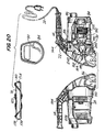
- the motor 24 is shown in FIGS. 18 to 24 and 30. It is contained in a motor compartment 26 shown in FIGS. 18 to 21 which are formed when the two halves or parts 28 and 30 ( see also FIGS. 18 to 21) are joined together along their longitudinal parting plane.
- Inlet vents 34 and outlet vents 36 for cooling air, which passes through the motor compartment and cools the motor, are provided.
- the nozzle 12 is part of a nozzle compartment having an access opening 40 which is closed by a door 42.
- the housing parts are preferably assembled by screws as will be discussed hereinafter in connection with the embodiment shown in FIG. 21. However, the parts may be secured together along the edges thereof which define the assembly plane. Glue or other securing means may be used.
- the bottom or belly of the housing 10 is generally cylindrical in its exterior surface.
- a flat 48 across the bottom surface provides a receptacle or well with longitudinally spaced end walls 50 and 52.
- the handle 14 is formed with longitudinally spaced projections 54 and 56. These projections 54 and 56 also define a well therebetween.
- the belly well and the top well on the handle provide areas around which the power line cord 20 can be wound to store the cord around the housing in a position where it will not slip off the housing because of the end walls 50, 52, 54 and 56, when the vacuum cleaner is not in use.
- louvers 60 behind the inlet vents and louvers 62 behind the outlet vents 36 are attached to the inside wall by baffles 64 and 66 as best shown in FIGS. 26 and 27.
- the cross-sectional configuration of the louvers and baffles is an inverted L. When taken with the housing wall between the vents, the louvers and baffles have a Z shape.
- the baffles 64 and the louvers 60 direct the cooling air inwardly.
- the baffles 66 and the louvers 62 direct the exhausting air outwardly and rearwardly to prevent recirculation into the inlet chamber.
- louver-baffle arrangement 60, 64 faces in an opposite direction from the louver-baffle arrangement 62, 66.
- FIG. 3 shows the dirt opening 68 at the bottom of the nozzle 12.
- a brush 70 is rotatably mounted in the nozzle compartment and is coupled to the motor shaft by an elastomeric (e.g., rubber) belt 72.
- a feature of the invention is the facility for mounting the brush into receptacles 74 and 76 at the ends of the nozzle compartment 60. These receptacles have means for preventing the brush 70 from falling out, if the belt 72 should break. There are no sole plates or other brackets to secure the brush 70 in the nozzle compartment 68.
- FIG. 3 also shows a boss 78 which receives one of the screws holding the bi-part housing together.
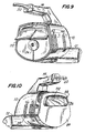
- FIG. 4 and also FIG. 8 show the bag assembly 16.
- This assembly is provided by a collar or ring 81 and the bag 18.
- the bag 18 has a gasket ring 80 which is recessed within the collar 81.
- the collar has a side hole 82 which is disposed forwardly of the gasket ring 80 in the assembly 16.
- the housing 10 has an end section 84, which may be a separate piece attached to the end of the housing (which is shown in FIG. 9) or is an integral part of the bi-part housing, as is the case illustrated in FIG. 21.
- This end section 84 has a snout 86 which enters the bag and directs dirt therein.
- the snout is the end of a dirt channel 88 which will be observed in FIGS. 9, 10 and 18 to 20 as well as FIG.
- the end section 84 has an opening 87 into a compartment 90 ( see FIGS. 18 to 20). Behind the opening 87 is a detent button 92. This button is tapered forwardly so that its rear (the part closer to the bag 18 than to the nozzle 12) defines a ramp over which the bag and its collar 81 can be slipped. Then, the detent button snaps out into the side opening 82. Because of the spacing of the gasket ring 80 with respect to the opening 82, the gasket ring 80 will abut against the back of the end section 84 and form a seal around the opening to the bag 18.
- a recess in the collar 81 is used. This recess engages a projection or rib 96 ( see FIG. 11) which is diametrically opposite to the detent opening 88.
- the rib 96 and the indentation 94 form a fulcrum, when they engage, around which the bag and collar can pivot as the side opening 82 moves over and into alignment with the detent button opening 87 and the detent button 92 snaps outwardly into the side opening 82 to lock the bag assembly in place at the rear of the housing 10.
- the end section 84 has an outer peripheral wall which is recessed below the outer peripheral wall of the housing to define a step 98. This step is approximately the thickness of the collar 81. The exterior surfaces of the collar 81 and the housing are thus aligned with each other so that they appear to be continuous.
- the bag assembly 16 is also shown in FIGS. 26A, 27A, 28 and 29.
- the gasket 80 is a ring of elastomeric plastic, such as PVC (e.g. 60 durometer) having an annular groove 100.
- the collar 81 is formed with a tongue 102, also annular, which receives the groove 100.
- the bag 18 may be sewn to the gasket ring 80. When the bag 18 becomes excessively dirty, it may be pulled out together with the gasket and washed and then replaced. The frictional tongue and groove fit holds the bag assembled to the collar 81 and facilitates removal thereof for cleaning or replacement.
- the gasket 80 is recessed within the collar 81 a distance from the side opening 82 to form a seal by abutment upon assembly. This distance or spacing of the gasket 80 is somewhat less than the distance between the gasket 80 and the front edge 91 of the collar 81. Thus, the gasket 80 will abut and form a seal with the rear face 89 of the end section 84 before the edge 91 meets the step 98.
- the compartment 92 has, around the opening 88, a lip or pair of lips best indicated at 104 and 106 in FIG. 8.
- the detent button 88 has side walls 106 from which tapered snap over or detent tabs 108 extend.
- the side walls define a compartment or pocket in which a rectangular body 110 of elastic material, such as an open celled foam rubber with resilent characteristic foam, is located.
- a rectangular body 110 of elastic material such as an open celled foam rubber with resilent characteristic foam
- the body 110 Upon assembly the body 110 enters the compartment 90 and forms a spring between the rear of the face of the detent button 88 and the rear wall of the compartment 90.
- the spring tabs 108 snap over the lip and prevent the button from leaving the compartment 90.
- the spring body 110 biases the button outwardly.
- the wedge or tapered shape of the button 88 is also shown in FIG. 28.
- FIG. 9 illustrates the bi-part housing 10 in process of being assembled. It will be observed that there is a deflector plate or partition 112 at the exit of the dirt channel 88. This partition enters into the snout 86.
- the agitator brush includes a brush roll 120 having at least one row of tufts or bristles helically disposed thereon. ( See also FIGS. 31 and 32).
- the brush roll may be made of wood or plastic. It has an axial opening or bore 126 with steps 128. These steps receive bearings 130 which may be of suitable bearing material (e.g., oil impregnated sintered iron).
- a shaft 132 extends through the axial hole 126.
- This shaft has end caps 134 and 136 at the opposite ends thereof. It will be appreciated that the shaft is held stationary while the brush and bearing rotate about it.
- the end caps have flanges which enter into annular grooves at the ends of the brush roll 120 and impede the entry of loose threads and dirt into the bearing shaft interface.
- a thrust washer 133 is located between the end cap 136 and the bearing 130 adjacent thereto. Only one thrust washer is needed because the resultant forces due to the belt act in one direction.
- the end cap 136 has a round (circular) boss 138.
- the end cap 134 has a circular boss 140 with flats 142. There may also be plastic spacers 133 on the outside faces of the bearings 130 as shown in FIG. 18.
- the receptacles 74 and 76 have their walls formed with inward projections 77 (such as wedges or barbs - see also FIG. 21) which define areas in the receptacles 74 and 76 in which the end caps 134 and 136 are received.
- the end caps 134 and 136 may be made of plastic, such as acetal.
- the distance across the diameter is smaller than the distance between the projections between the side walls. If the projections are only on the end walls, then the axial distance between the end caps is greater than the axial distance between the projections. In other words, there are two alternative assembly means. Therefore, the brush assemblies are snapped into the receptacles and are held there without falling out, even if the belt 72 breaks and in spite of there being no sole plate or other hold-in device for the brush 70.
- the receptacle 74 is wider than the receptacle 76 between their side walls. This enables the brush to be inserted one way with the larger end cap 136 in the larger receptacle and the smaller end cap 134 into the smaller receptacle. This selective assembly assures that the thrust washer 133 will be in a position to take the thrust forces due to the belt.
- housing halves 28 and 30 are mirror images of each other. They define the motor compartment 26, a fan compartment 140 and the nozzle compartment 86.
- the handle 14 is hollow and has a post 142 around which the line cord 20 extends and is held so as to provide strain relief.
- the handle also has a pocket 144 in which the switch 22 is disposed ( see especially FIG. 20).
- the wires for powering the motor 24 extend through a conduit tube 145.
- the tube 145 extends through the dirt channel 88 (see FIG. 20).
- the conduit tube 145 may be formed by hemi-cylindrical sections molded in the housing parts 28 & 30. See FIG. 21.
- the housing halves 26 and 28 are formed with alignment posts and holes and may be glued together.
- FIG. 21 which shows the housing half 30 (the other half 28 being a mirror image)
- six holes 146 which receive self-threading screws through aligned holes in the other housing part 28 are used to assemble the parts together.
- Tongues 148 see also FIGS. 22 to 24
- Tongues 148 which are received in grooves in the other housing part 28 define the partitions between these housing halves and make the compartments 26, 140 and 86 sufficiently airtight.
- the motor 24 has a shaft 160 with a belt pulley section 162 at the forward end thereof.
- the free end 164 of the motor shaft faces the opening 40 as best shown in FIG. 20.
- the door 42 ( see FIG. 17) has a hollow post 170 and a gusset 172 with a hole 174 therethrough.
- the post and gusset 171/172 are on the inside of the door and the door has a lip 176 which engages the upper edge of the opening 40.
- the axis of the post 170 is aligned with the end of the shaft end 164 and the post is of larger diameter than the shaft end. When closed the post 170 is in the immediate proximity (slightly spaced from the end 164.
- the belt will engage the end of the post 170 and cannot slip off the pulley 162.
- the screw 162 passes through a sleeve section 178 from the hole 44 into a threaded bore 180.
- the screw extends through the hole 174 in the gusset 172.
- the post may be a cross or bar in cross-section which extends beyond the diameter of the shaft end 164.
- the motor 24 has a cage 190 with ribs providing passages.
- This cage is connected through bridges 192 and 194 which attach the cage to the stator of the motor which includes coils and laminations 196.
- Further bridges 198 connect the brush and rear bearing bracket assembly 199 of the motor to the rest of the motor.
- the armature is wound on the shaft and there is an annular space extending longitudinally between the armature and the stator (laminations and stator coil 196) section.
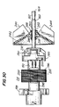
- the stator section has flats, one of which is indicated at 200, the other flat is diametrically opposite to the flat 200. These flats are shown at 200 and 200' in FIG. 30.
- the cage 190 contains a bearing for the shaft 160. Another bearing is contained in the brush and rear bearing assembly 199.
- the motor is contained in the motor compartment 26.
- a pair of partitions 202 and 204 (which are formed when the housing halves 28 & 30 are assembled) divide the motor compartment 26 into three chambers, namely, an inlet chamber 206, and outlet chamber 208 and a cooling chamber 210 intermediate the inlet and outlet chambers 206 and 208.
- the shape of these partitions and especially the shape of the holes therethrough in which the motor is mounted is best shown in FIGS. 22 and 23 which show halves of each hole.
- the mirror image of these sections in the housing part 28 completes the partitions.
- the hole 214 formed in the partition 202 is circular, while the hole 216 in the partition 204 is circular with flats 218.
- the rear ring 193 of the cage 190 fits in the circular opening 214.
- the flats 200 & 200' on the laminations of the stator 196 are located against the flats 218 and fit in the opening 216 in the partition 204.
- the rear wall 220 of the motor chamber also has an opening 223 which receives the bearing cups of the brush and bearing assembly 199 of the motor 24.
- the inner ring 193 of the cage 190 has tabs 222 which fit into pockets 226 (see also FIG. 25). This further maintains the motor 24 in position and prevents the rotation of the stationary parts thereof.
- the motor is merely dropped into one half section 30 and the other half section placed on to trap and secure the motor in place.
- the cooling chamber has no vents and no communication with the inlet and outlet chambers except through the passageways in the motor.
- a motor cooling fan inside the brush cage which is shown at 230 in FIG. 30 assists in drawing inlet air into the inlet chamber 206.
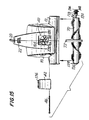
- the suction fan 240 has a conical base 242 from which extend a plurality of blades 244 which are spaced at angular increments from each other around the base 242.
- the fan 240 also has a collar 246 ( see FIG: 30).
- This collar is provided with a metal insert 248 which is preferably ultrasonically bonded in the axial bore 250 of the collar 246.
- a metal (e.g., brass) softer than the metal (e.g., steel) of the shaft 160 is used for the insert.
- the portion of the shaft 160 on which the fan is mounted is provided with a plurality of splines 252, for example four splines which are spaced from each other around the periphery of the shaft.
- the fan is mounted by pressing it over the splines, in effect swaging the insert to the splines 252. This may be done in a press with a stop to assure that the fan is located on the shaft portion which is located in the fan chamber 86.
Landscapes
- Nozzles For Electric Vacuum Cleaners (AREA)
- Electric Vacuum Cleaner (AREA)
Applications Claiming Priority (2)
| Application Number | Priority Date | Filing Date | Title |
|---|---|---|---|
| US464252 | 1983-02-07 | ||
| US46425290A | 1990-01-12 | 1990-01-12 |
Publications (2)
| Publication Number | Publication Date |
|---|---|
| EP0437109A2 true EP0437109A2 (de) | 1991-07-17 |
| EP0437109A3 EP0437109A3 (en) | 1991-10-30 |
Family
ID=23843154
Family Applications (1)
| Application Number | Title | Priority Date | Filing Date |
|---|---|---|---|
| EP19900314401 Withdrawn EP0437109A3 (en) | 1990-01-12 | 1990-12-28 | Hand-held corded vacuum cleaner |
Country Status (4)
| Country | Link |
|---|---|
| US (1) | US5129128A (de) |
| EP (1) | EP0437109A3 (de) |
| JP (1) | JPH04329915A (de) |
| CA (1) | CA2033875A1 (de) |
Cited By (2)
| Publication number | Priority date | Publication date | Assignee | Title |
|---|---|---|---|---|
| EP0605985A1 (de) * | 1993-01-08 | 1994-07-13 | Royal Appliance Manufacturing Co. | Isolierter Riementrieb eines Staubsaugersmotors |
| US6029313A (en) * | 1996-11-15 | 2000-02-29 | Black & Decker, Inc. | Vacuum cleaner with cantilevered drive system and removable belt access door |
Families Citing this family (21)
| Publication number | Priority date | Publication date | Assignee | Title |
|---|---|---|---|---|
| US5388302A (en) * | 1993-01-08 | 1995-02-14 | Black & Decker Inc. | Vacuum cleaner housing and airflow chamber |
| USD352141S (en) | 1993-01-08 | 1994-11-01 | Black & Decker Inc. | Hand-held vacuum cleaner |
| US5331716A (en) * | 1993-01-08 | 1994-07-26 | Black & Decker Inc. | Vacuum cleaner with extendable hose and brush disengagement |
| US5421058A (en) * | 1993-10-01 | 1995-06-06 | Royal Appliance Mfg. Co. | Hand-held vacuum cleaner |
| US5504970A (en) * | 1994-06-24 | 1996-04-09 | The Scott Fetzer Company | Hand-held vacuum cleaner |
| US5586358A (en) * | 1994-08-15 | 1996-12-24 | Bissell | Hand carriable vacuum cleaner with accessory attachment |
| USD368558S (en) | 1994-09-23 | 1996-04-02 | Ryobi North America Corp. | Portable vacuum cleaner |
| USD368992S (en) | 1994-09-27 | 1996-04-16 | Bissell Inc. | Hand-held vacuum cleaner |
| TW271384B (en) * | 1995-01-13 | 1996-03-01 | Black & Decker Inc | Vacuum cleaner |
| US5632060A (en) * | 1995-08-04 | 1997-05-27 | Bissell Inc. | Vacuum cleaner with agitation member drive belt access panel |
| US6167587B1 (en) | 1997-07-09 | 2001-01-02 | Bissell Homecare, Inc. | Upright extraction cleaning machine |
| USRE39304E1 (en) * | 1997-07-09 | 2006-09-26 | Bissell Homecare, Inc. | Upright extraction cleaning machine |
| US6438793B1 (en) | 1997-07-09 | 2002-08-27 | Bissell Homecare, Inc. | Upright extraction cleaning machine |
| US6226832B1 (en) | 1998-04-23 | 2001-05-08 | Matsushita Home Appliance Corporation Of America | Easy maintenance vacuum cleaner |
| US6098245A (en) * | 1998-09-30 | 2000-08-08 | Ryobi North America, Inc. | Vacuum cleaner motor assembly |
| US6497001B2 (en) | 2001-01-12 | 2002-12-24 | Royal Appliance Mfg. Co. | Hand-held vacuum cleaner with a detachable head |
| US7418763B2 (en) * | 2003-02-26 | 2008-09-02 | Black & Decker Inc. | Hand vacuum with filter indicator |
| US20090107413A1 (en) * | 2007-10-30 | 2009-04-30 | Assaf Shiloni | Two handle vacuum cleaner for animal grooming |
| USD626708S1 (en) | 2008-03-11 | 2010-11-02 | Royal Appliance Mfg. Co. | Hand vacuum |
| BRPI0919686A2 (pt) * | 2008-10-22 | 2021-04-20 | Rosemount Inc | sensor/transmissor plug-and-play para instrumentação de processo |
| USD693068S1 (en) * | 2012-02-02 | 2013-11-05 | Foshan Shunde Xinshengyuan Electrical Applicances Co., Ltd. | Pet hair dryer |
Family Cites Families (67)
| Publication number | Priority date | Publication date | Assignee | Title |
|---|---|---|---|---|
| DE634049C (de) * | 1936-08-14 | Siemens Schuckertwerke Akt Ges | Handgriff fuer Staubsauger mit einer Haltevorrichtung fuer das aufgewickelte Kabel | |
| US32751A (en) * | 1861-07-09 | Jeremiah carhart | ||
| US1136434A (en) * | 1906-01-30 | 1915-04-20 | Modern Compressed Air Cleaning Co | Pneumatic carpet-cleaner. |
| US1130114A (en) * | 1914-11-27 | 1915-03-02 | Santo Mfg Company | Vacuum cleaning apparatus. |
| US1740918A (en) * | 1927-02-28 | 1929-12-24 | Alex A Clarke | Air-suction apparatus |
| US1823726A (en) * | 1927-06-06 | 1931-09-15 | Electric Vacuum Cleaner Co | Bag support for vacuum cleaners |
| US1727922A (en) * | 1927-07-19 | 1929-09-10 | Wise Mcclung Corp | Casing for vacuum cleaners |
| US1856136A (en) * | 1927-11-12 | 1932-05-03 | Company The Cleveland Trust | Suction cleaner |
| US1903855A (en) * | 1929-02-25 | 1933-04-18 | Townsend Arthur | Electrical vacuum cleaner |
| US1933492A (en) * | 1929-04-27 | 1933-10-31 | Johnson & Son Inc S C | Floor polishing and vacuum cleaning machine |
| GB342185A (en) * | 1930-03-11 | 1931-01-29 | Alex Alfred Clarke | Improvements in or relating to suction cleaners |
| US1878858A (en) * | 1930-05-05 | 1932-09-20 | Hoover Co | Suction cleaner |
| US1949052A (en) * | 1930-11-12 | 1934-02-27 | Ind Improvements Inc | Suction cleaning apparatus |
| US1946585A (en) * | 1930-12-12 | 1934-02-13 | Quadrex Corp | Floor aligning sweeper |
| US1918695A (en) * | 1931-02-07 | 1933-07-18 | Gilbert Co A C | Vacuum cleaner motor |
| US1970665A (en) * | 1931-04-10 | 1934-08-21 | P A Geier Co | Suction cleaner |
| US2130325A (en) * | 1935-02-18 | 1938-09-13 | Scott & Fetzer Co | Suction sweeper |
| US2244943A (en) * | 1936-07-27 | 1941-06-10 | Air Way Electric Appl Corp | Vacuum cleaner |
| US2092043A (en) * | 1936-11-28 | 1937-09-07 | Westinghouse Electric & Mfg Co | Perforated cover and baffle for railway motors |
| US2149138A (en) * | 1938-03-11 | 1939-02-28 | Hygienic Dust Bag Corp | Belt retaining device for vacuum cleaners |
| US2263762A (en) * | 1939-02-15 | 1941-11-25 | Air Way Electric Appl Corp | Vacuum cleaner |
| US2239762A (en) * | 1939-03-24 | 1941-04-29 | Westinghouse Electric & Mfg Co | Suction cleaning apparatus |
| US2272985A (en) * | 1939-10-14 | 1942-02-10 | Spencer Turbine Co | Motor mounting for vacuum cleaners |
| US2314334A (en) * | 1940-11-06 | 1943-03-23 | Apex Electrical Mfg Co | Suction cleaner |
| US2340379A (en) * | 1940-12-09 | 1944-02-01 | Hoover Co | Suction cleaner |
| US2309583A (en) * | 1941-02-20 | 1943-01-26 | Apex Electrical Mfg Co | Suction cleaner |
| US2395430A (en) * | 1941-10-11 | 1946-02-26 | Hoover Co | Suction cleaner |
| US2319194A (en) * | 1941-12-05 | 1943-05-11 | Casco Products Corp | Electric motor |
| US2406915A (en) * | 1943-04-26 | 1946-09-03 | Hoover Co | Suction cleaner |
| GB584478A (en) * | 1943-12-22 | 1947-01-15 | Eureka Vacuum Cleaner Co | Improvements in or relating to suction cleaners |
| US2538464A (en) * | 1945-10-02 | 1951-01-16 | Scott & Fetzer Co | Detachable mounting for vacuum cleaner nozzles with power-driven brush |
| US2460851A (en) * | 1946-01-26 | 1949-02-08 | Eureka Williams Corp | Bag coupling for suction cleaners |
| US2428133A (en) * | 1946-07-09 | 1947-09-30 | Bart P Yogan | Illuminated toy |
| US2474439A (en) * | 1947-09-03 | 1949-06-28 | Hoover Co | Electric motor |
| GB673669A (en) * | 1949-05-03 | 1952-06-11 | Emi Ltd | Improvements in or relating to vacuum cleaners |
| US2693542A (en) * | 1952-01-30 | 1954-11-02 | Hoover Co | Electric motor |
| US2767904A (en) * | 1953-03-23 | 1956-10-23 | Doyle Vacuum Cleaner Co | Motor for vacuum producing machines |
| US2823411A (en) * | 1953-06-22 | 1958-02-18 | James B Kirby | Vacuum cleaner |
| FR1153922A (fr) * | 1955-05-20 | 1958-03-28 | Borg Warner | Perfectionnements aux ensembles de pompes |
| US3217351A (en) * | 1962-10-09 | 1965-11-16 | Gen Electric | Vacuum cleaner |
| US3312386A (en) * | 1964-12-21 | 1967-04-04 | Ametek Inc | Fan |
| US3302047A (en) * | 1964-12-24 | 1967-01-31 | Black & Decker Mfg Co | Fan assembly for high-torque application |
| US3341113A (en) * | 1965-10-21 | 1967-09-12 | Ametek Inc | Fluid moving system and an electric motor-pump unit therefor |
| US3437424A (en) * | 1965-11-26 | 1969-04-08 | Royal Appliance Mfg Co Inc | Suction cleaner nozzle construction |
| DE1981962U (de) * | 1967-07-28 | 1968-03-28 | Bosch Gmbh Robert | Handstaubsauger. |
| US3458739A (en) * | 1967-09-13 | 1969-07-29 | Smith Corp A O | Air cooled motor |
| US3608333A (en) * | 1968-06-20 | 1971-09-28 | Bison Mfg Co Inc | Vacuum cleaner and power unit |
| FR1598135A (de) * | 1968-12-26 | 1970-06-29 | ||
| US3802025A (en) * | 1972-06-30 | 1974-04-09 | Fuller Co H | Litter vacuum cleaner |
| DE2318425C2 (de) * | 1973-04-12 | 1982-05-13 | Vorwerk & Co Interholding Gmbh, 5600 Wuppertal | Höhenverstell- und Wechseleinrichtung für eine antreibbare Walzenbürste eines Bodenpflegegerätes mit Staubabsaugung |
| US3829721A (en) * | 1973-07-30 | 1974-08-13 | Black & Decker Mfg Co | Air flow baffle construction for electric motor devices |
| US4120616A (en) * | 1975-10-06 | 1978-10-17 | Breuer Electric Manufacturing Company | Vacuum cleaner-blower assembly with sound absorbing arrangement |
| US4167801A (en) * | 1978-02-24 | 1979-09-18 | Royal Appliance Manufacturing Company | Suction cleaner power nozzle construction |
| SE415696B (sv) * | 1979-01-18 | 1980-10-20 | Flygt Ab | anrodning vid avtetat drivaggregat |
| DE2934043A1 (de) * | 1979-08-23 | 1981-03-26 | Rommag P. Wörwag & Co., Romanshorn | Buerststaubsauger |
| US4361929A (en) * | 1981-03-26 | 1982-12-07 | Black & Decker Inc. | Vacuum cleaner tool having a two-position rotary brush |
| JPS57122839A (en) * | 1981-11-11 | 1982-07-30 | Hitachi Ltd | Cleaner |
| US4518325A (en) * | 1983-07-11 | 1985-05-21 | Kingston James E | Aerifying device for whirlpool bath or tub |
| WO1985004562A1 (en) * | 1984-04-13 | 1985-10-24 | Royal Appliance Manufacturing Company | Hand vacuum |
| FR2562775B1 (fr) * | 1984-04-13 | 1989-12-22 | Taravel Bernard | Brosse a poils retractables elastiquement, notamment pour le brossage de surfaces de relief complexe telles que les dents |
| US4512057A (en) * | 1984-04-30 | 1985-04-23 | The Singer Company | Floor care appliance |
| GB2224196B (en) * | 1984-11-09 | 1990-07-25 | Royal Appliance Mfg | Hand held vacuum cleaner |
| US4633543A (en) * | 1984-11-09 | 1987-01-06 | Royal Appliance Mfg. Co. | Hand vacuum cleaner |
| US4601735A (en) * | 1985-01-18 | 1986-07-22 | Royal Appliance Mfg. Co. | Vacuum bag attachment device |
| CA1223754A (en) * | 1985-12-02 | 1987-07-07 | Laurent Beaudoin | Guide for a driven endless belt |
| US4685171A (en) * | 1986-05-08 | 1987-08-11 | Iona Appliances Inc. | Guide for a driven endless belt |
| US4800614A (en) * | 1987-04-30 | 1989-01-31 | Royal Appliance Mfg. Co. | Adaptor and bag insert |
-
1990
- 1990-12-28 EP EP19900314401 patent/EP0437109A3/en not_active Withdrawn
-
1991
- 1991-01-09 CA CA002033875A patent/CA2033875A1/en not_active Abandoned
- 1991-01-11 JP JP3012525A patent/JPH04329915A/ja active Pending
- 1991-06-25 US US07/722,370 patent/US5129128A/en not_active Expired - Fee Related
Cited By (2)
| Publication number | Priority date | Publication date | Assignee | Title |
|---|---|---|---|---|
| EP0605985A1 (de) * | 1993-01-08 | 1994-07-13 | Royal Appliance Manufacturing Co. | Isolierter Riementrieb eines Staubsaugersmotors |
| US6029313A (en) * | 1996-11-15 | 2000-02-29 | Black & Decker, Inc. | Vacuum cleaner with cantilevered drive system and removable belt access door |
Also Published As
| Publication number | Publication date |
|---|---|
| CA2033875A1 (en) | 1991-07-13 |
| JPH04329915A (ja) | 1992-11-18 |
| EP0437109A3 (en) | 1991-10-30 |
| US5129128A (en) | 1992-07-14 |
Similar Documents
| Publication | Publication Date | Title |
|---|---|---|
| EP0437109A2 (de) | Handstaubsauger mit Anschlusskabel | |
| US6513190B1 (en) | Turbine powered vacuum cleaner nozzle | |
| US5329666A (en) | Vacuum cleaner | |
| US3477087A (en) | Vacuum cleaner | |
| US5787546A (en) | Vacuum cleaner | |
| US4665582A (en) | Lightweight battery powered suction broom | |
| US3334370A (en) | Lightweight portable vacuum cleaner | |
| US5551122A (en) | Corded handheld vacuum cleaner | |
| KR20130137580A (ko) | 사이클론 집진장치 및 이를 구비한 핸디형 진공청소기 | |
| EP0493929A1 (de) | Handstaubsauger | |
| US5218736A (en) | Vacuum cleaner | |
| CN212382567U (zh) | 清洁头及手持吸尘器 | |
| US5388302A (en) | Vacuum cleaner housing and airflow chamber | |
| CN213588156U (zh) | 手持吸尘器 | |
| CN111887764A (zh) | 清洁头及手持吸尘器 | |
| CN217547913U (zh) | 一种地刷组件及清洁设备 | |
| GB2056847A (en) | Brushing hand-held vacuum cleaner | |
| JPH11216084A (ja) | 電気掃除機用吸込み口体及びこれを備えた電気掃除機 | |
| KR100753649B1 (ko) | 브러시 겸용 물걸레 청소구 | |
| CN115715658B (zh) | 地刷组件及清洁设备 | |
| CN213588154U (zh) | 手持吸尘器 | |
| CN213588153U (zh) | 清洁头及手持吸尘器 | |
| JP3163287B2 (ja) | 吸込み口体及び電気掃除機 | |
| US2693542A (en) | Electric motor | |
| CN210008970U (zh) | 地刷组件及具有其的尘气处理装置 |
Legal Events
| Date | Code | Title | Description |
|---|---|---|---|
| PUAI | Public reference made under article 153(3) epc to a published international application that has entered the european phase |
Free format text: ORIGINAL CODE: 0009012 |
|
| AK | Designated contracting states |
Kind code of ref document: A2 Designated state(s): DE FR GB IT |
|
| PUAL | Search report despatched |
Free format text: ORIGINAL CODE: 0009013 |
|
| AK | Designated contracting states |
Kind code of ref document: A3 Designated state(s): DE FR GB IT |
|
| 17P | Request for examination filed |
Effective date: 19920423 |
|
| 17Q | First examination report despatched |
Effective date: 19930922 |
|
| STAA | Information on the status of an ep patent application or granted ep patent |
Free format text: STATUS: THE APPLICATION IS DEEMED TO BE WITHDRAWN |
|
| 18D | Application deemed to be withdrawn |
Effective date: 19940203 |