EP0437115B1 - Coupleur à large bande du type ligne à bande - Google Patents
Coupleur à large bande du type ligne à bande Download PDFInfo
- Publication number
- EP0437115B1 EP0437115B1 EP90314453A EP90314453A EP0437115B1 EP 0437115 B1 EP0437115 B1 EP 0437115B1 EP 90314453 A EP90314453 A EP 90314453A EP 90314453 A EP90314453 A EP 90314453A EP 0437115 B1 EP0437115 B1 EP 0437115B1
- Authority
- EP
- European Patent Office
- Prior art keywords
- section
- sheet
- coupler
- dielectric
- disposed
- Prior art date
- Legal status (The legal status is an assumption and is not a legal conclusion. Google has not performed a legal analysis and makes no representation as to the accuracy of the status listed.)
- Expired - Lifetime
Links
- 230000008878 coupling Effects 0.000 claims description 32
- 238000010168 coupling process Methods 0.000 claims description 32
- 238000005859 coupling reaction Methods 0.000 claims description 32
- 239000000758 substrate Substances 0.000 claims description 20
- 239000003989 dielectric material Substances 0.000 claims description 12
- 239000006261 foam material Substances 0.000 claims description 3
- 239000004952 Polyamide Substances 0.000 claims 1
- 229920002647 polyamide Polymers 0.000 claims 1
- 239000011800 void material Substances 0.000 claims 1
- 238000013461 design Methods 0.000 description 6
- 230000004044 response Effects 0.000 description 4
- 230000005540 biological transmission Effects 0.000 description 3
- 230000000694 effects Effects 0.000 description 3
- 230000001902 propagating effect Effects 0.000 description 3
- 239000000463 material Substances 0.000 description 2
- 238000000034 method Methods 0.000 description 2
- 239000007787 solid Substances 0.000 description 2
- 125000006850 spacer group Chemical group 0.000 description 2
- 239000004642 Polyimide Substances 0.000 description 1
- 230000008901 benefit Effects 0.000 description 1
- 230000008859 change Effects 0.000 description 1
- 230000001419 dependent effect Effects 0.000 description 1
- 230000005684 electric field Effects 0.000 description 1
- 238000003780 insertion Methods 0.000 description 1
- 230000037431 insertion Effects 0.000 description 1
- 238000002955 isolation Methods 0.000 description 1
- 238000004519 manufacturing process Methods 0.000 description 1
- 230000004048 modification Effects 0.000 description 1
- 238000012986 modification Methods 0.000 description 1
- 238000012544 monitoring process Methods 0.000 description 1
- 238000007747 plating Methods 0.000 description 1
- 229920001721 polyimide Polymers 0.000 description 1
- 230000000644 propagated effect Effects 0.000 description 1
- 239000000377 silicon dioxide Substances 0.000 description 1
Images

Classifications
-
- H—ELECTRICITY
- H01—ELECTRIC ELEMENTS
- H01P—WAVEGUIDES; RESONATORS, LINES, OR OTHER DEVICES OF THE WAVEGUIDE TYPE
- H01P5/00—Coupling devices of the waveguide type
- H01P5/12—Coupling devices having more than two ports
- H01P5/16—Conjugate devices, i.e. devices having at least one port decoupled from one other port
- H01P5/18—Conjugate devices, i.e. devices having at least one port decoupled from one other port consisting of two coupled guides, e.g. directional couplers
- H01P5/184—Conjugate devices, i.e. devices having at least one port decoupled from one other port consisting of two coupled guides, e.g. directional couplers the guides being strip lines or microstrips
- H01P5/185—Edge coupled lines
Definitions
- This invention relates to a directional coupler comprising: a first ground plane, a second ground plane, a dielectric substrate disposed between the ground planes, circuitry disposed on the substrate and having a main line with a main line coupling section and a branch line with a branch line coupling section, the coupling sections being shaped and arranged to couple microwave energy from one line to the other line, a first sheet of dielectric material disposed between the first ground plane and the said circuitry, and a second sheet of dielectric material disposed between the second ground plane and the said circuitry.
- directional couplers fabricated in stripline may be used in many applications in microwave circuitry.
- a so-called suspended stripline coupler may be used to advantage.
- Such a coupler differs from a conventional stripline coupler in that a suspended stripline coupler comprises a printed circuit of appropriate shape supported (without a solid spacer having a dielectric constant greater than unity) between two opposing ground planes.
- the absence of a solid dielectric material reduces, as compared with a conventional stripline coupler, the susceptibleness of a suspended stripline coupler to changes in insertion loss and directivity when the frequency of an impressed microwave signal is changed.
- a suspended stripline coupler fabricated in any known manner is satisfactorily operable on microwave energy only at a frequency that is within a relatively narrow band of frequencies encompassing a design frequency.
- many applications require satisfactory operation at any frequency within a relatively wide band of frequencies.
- a directional coupler operate satisfactorily over an extremely wide frequency band. Satisfactory operation, i.e., flat coupling over a broad frequency range, requires a multi-section coupler in which "even" and "odd" mode propagation of microwave energy occurs.
- An "even" mode of propagation means that an effective open circuit appears between the main and branch lines of a directional coupler.
- An "odd” mode means that an effective short circuit appears between the main and branch lines of a directional coupler. Because the cross sectior of suspended stripline is not homogeneous, the phase velocity of propagation in the odd mode is less than that in the even mode, with the result that flat coupling and high directivity of known multi-section couplers may not be satisfactorily achieved throughout a wide band of frequencies.
- a dielectric overlay be used to improve the isolation of a microstrip coupler by reducing the differences between or equalising the odd and even phase velocities.
- the proposed structure has a dielectric substrate with a ground plane on its lower surface and a substantially straight main line and a substantially U-shaped branch line on its upper surface, a central section of the main line and the base of the U-shape being disposed adjacent each other as coupling sections.
- the dielectric overlay is substantially in the form of a truncated lozenge-shaped sheet of dielectric having six sides which is laid transversely across the coupling sections of the main and branch lines.
- the design of the overlay is by a full-wave analysis which is based on a spectral-domain method that involves solving an eigenvalue problem in the Fourier transform domain.
- a directional coupler of the kind defined hereinbefore at the beginning is described by O. Isheda, Y. Isota, M. Miyazaki, F. Takeda, and N. Takeuchi in an article entitled "An Asymmetrical Suspended Stripline Directional Coupler" at pages 333 to 334 in the Transactions of the IECE of Japan, Vol. E69, No. 4, April 1986.
- the main line consists of substantially straight strips on the upper and lower surfaces of the dielectric substrate
- the branch line consists of substantially U-shaped strips on the upper and lower surfaces of the substrate.
- the bases of the U-shapes and the central sections of the main line strips are adjacent each other to serve as coupling sections.
- the base section of the upper branch strip is made wider than its arm portions, and the central portion of the upper main line strip is made narrower than its end portions.
- the base section of the lower branch strip is made narrower than its arm portions, and the central portion of the lower main line strip is made wider than its end portions.
- the wide base section of the upper branch strip and the wide central section of the lower main line strip are arranged to partially overlap each other. The purpose of this asymmetrical arrangement is to provide an intermediate coupling value, i.e. 5 to 9 dB. It is also observed there that, to improve the directivity, the first and second sheets of dielectric material are provided respectively on the first and second ground planes.
- US-A-3 581 243 describes a strip-type transmission line directional coupler comprising upper and lower ground planes, circuitry consisting of a substantially straight main line strip and a substantially U-shaped branch line strip arranged with its base section adjacent a central section of the main line strip, first and second sheets of a primary dielectric medium arranged respectively between the circuitry and the upper and lower ground planes, and a pair of inserts of a different dielectric medium, which are disposed either above and below the central coupling section of the main line strip, or above and below the base section of the branch line strip.
- the velocity of propagation of a wave in the main line is controlled by the dielectric medium of the inserts
- the velocity of propagation in the branch line is controlled by the dielectric medium of the first and second sheets.
- the directivity of the coupler is defined as the ratio of a response to a wave travelling in a favoured direction to a response to a wave travelling in a backward direction. It is stated that by controlling the velocity of propagation of the wave travelling on the main line with respect to the velocity of propagation of the wave travelling on the branch line, the response to the wave travelling in the favoured direction is not greatly changed but the response to the wave travelling in the backward direction is minimized, whereby higher directivity is obtained. It is further stated that when it is desired that the coupling be nearly constant over a very wide frequency range, the branch line may be made of a number of sections, such that a three section or a five section coupler is formed.
- Another object of this invention is to provide a multi-section directional coupler in which the phase velocities of microwave energy propagated in either the odd or even mode of propagation are substantially the same throughout a wide band of operating frequencies.
- a directional coupler of the kind defined hereinbefore at the beginning is characterised by a third sheet of different dielectric material so shaped and arranged to correspond to and overlap partially the main line coupling section as to equalise phase velocities of microwave energy in both the odd and even modes of propagation passing in operation through the main line coupling section, and a fourth sheet of the different dielectric material so shaped and arranged to correspond to and overlap partially the branch line coupling section as to equalise phase velocities of microwave energy in both the odd and even modes of propagation passing in operation through the branch line coupling section, the third sheet being disposed between the main line coupling section and the first sheet, and the fourth sheet being disposed between the branch line coupling section and the first sheet, and in that the first and second sheets have a dielectric constant of approximately unity.
- a preferred embodiment of this invention takes the form of a four-port suspended stripline coupler adapted to divide microwave power applied at a first port into unequal amounts at a second and third port, with substantially no power at a fourth port, such coupler being characterized by a matching arrangement to match the phase velocities within such couple of microwave energy propagating in the odd and even modes.
- a small portion of microwave energy being transmitted may be sampled, thereby to permit monitoring of the level of the transmitted microwave energy.
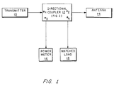
- a transmitter 10 is connected to a first port (port #1) of a directional coupler 12, and an antenna 14 is connected to a second port (port #2) of such coupler.
- a power meter 16 and a matched load 18 are connected to the third and fourth ports (port #3 and port #4).
- the directional coupler 12 is operative in a known manner: (a) to pass the greater portion of microwave energy from the transmitter 10 to the antenna 14 and to pass the remaining portion of such energy to the power meter 16, and not to the matched load 18; and, (b) to pass any microwave energy traveling from the antenna 14 to the matched load 18 and to the transmitter 10, and not to the power meter 16.
- the directivity i.e., the degree to which a stripline coupler attains the just mentioned operational objects throughout a band of frequencies, is dependent upon the structural details of any stripline coupler.
- An acceptable figure for directivity is 20 dB.
- a conventional stripline coupler based on a design suggested by S.B. Cohn, in an article entitled “Shielded Coupled-Strip Transmission Line,” published in October, 1955, in the IRE (Institute of Radio Engineers) Transactions, MTT pages 29-38 is a relatively narrow band device.
- a modified version of the conventional stripline coupler (which modification is accomplished simply by providing an air gap between the main line and the branch lines) is a relatively narrow band device.
- FIG. 2 it may be seen that, for simplicity of illustration and clarity of explanation, elements not essential to an understanding of the invention have been omitted. For example, it will be apparent to one of skill in the art that appropriately configured connectors and transmission lines would be provided in a production model to permit use of the stripline coupler shown in FIG. 2 in a circuit such as the one shown in FIG. 1.
- the stripline coupler shown in FIG. 2 comprises printed circuitry (to be described) supported between an upper ground plane 20U and a lower ground plane 20L.
- Spacers 22U, 22L formed from a closed cell polyimide foam material having a dielectric constant substantially equal to unity
- a satisfactory foam material is ROHACELL, (Registered Trade Mark of Rohm GmbH), manufactured by CYRO Industries of Orange, New Jersey.
- ROHACELL Registered Trade Mark of Rohm GmbH
- the just described elements form a suspended stripline coupler because the printed circuitry is arranged to form a pair of directional couplers on opposing sides of a support 24.
- the dielectric constant of the material of support 24 is not critical.
- the directional coupler comprises an upper main line 26U, and a lower main line 26L, each having a five-section coupler (not numbered). Further, the directional coupler comprises an upper branch line 28U and a lower branch line 28L, each also having a five-section coupler (not numbered). Via holes plated through the support 24 form shorting posts electrically connecting (as shown by shorting posts 30) the upper and lower branch lines 28U, 28L. Similarly formed shorting posts (not numbered) are provided to connect the upper and lower main lines 26U, 26L. Finally, wall defining posts, such as those designated wall posts 32, are formed, as shown by plating through via holes adjacent to the printed lines or by inserting electrically conductive pins through vias. The wall defining posts reduce leakage effects to a minimum in a known manner.
- dielectric loading is provided adjacent to each one of the five-section couplers. Such loading is effective to equalize the phase velocities of the microwave energy passing through the illustrated arrangement in both the odd and even modes of propagation. It has been here realized that: (a) the concentration of the electric field in the gap between the five-section couplers is greater for the odd mode of propagation than for the even mode; (b) the phase velocity of the even mode of propagation is greater than the phase velocity of the odd mode; and, (c) the difference between the phase velocities limits the band-width of a suspended stripline coupler. Therefore, if dielectric loading is effected in such a way as to slow down the phase velocity of microwave energy propagating in the even mode, more than the phase velocity of microwave energy propagating in the odd mode, changes in characteristics with changes in operating frequency may be minimized.
- a dielectric load (such as dielectric load 34) is disposed partially to overlap each one of the five-section couplers.
- each dielectric load is shaped so as to correspond with the steps in the printed circuitry making up each five-section coupler.
- the thickness of each dielectric load 34 is less than the spacing between the five-section couplers and the opposing ground planes 20U, 20L.
- the dielectric constant of the material of each dielectric load 34 is approximately 2.2. Such constant may, however, be varied.
- the position of each dielectric load relative to the associated five-section coupler may best be determined empirically to optimize the flatness of coupling over a relatively broad band of frequencies.
- dielectric loading is provided in a suspended strip line coupler, such loading being effective to equalise the phase velocities of microwave energy in different modes of operation.
- the number of sections in the coupler may be changed with a concomitant change in the shape of the dielectric load being made.
Landscapes
- Waveguides (AREA)
Claims (5)
- Coupleur directionnel comprenant :
une première plaque de terre (20U), une deuxième plaque de terre (20L), un substrat diélectrique (24) intercalé entre les plaques de terre (20U,20L), un ensemble de circuits (26,28) disposé sur le substrat (24) et ayant une ligne principale (26) dotée d'une section de couplage de ligne principale et une ligne de dérivation (28) dotée d'une section de couplage de ligne de dérivation, les sections de couplage étant adaptées et disposées de manière à coupler une énergie hyperfréquence d'une ligne à l'autre, une première feuille (22U) de matériau diélectrique intercalée entre la première plaque de terre (20U) et ledit ensemble de circuits, et une deuxième feuille (22L) de matériau diélectrique intercalée entre la deuxième plaque de terre (20L) et ledit ensemble de circuits, caractérisé par une troisième feuille (34) de matériau diélectrique différent, adaptée et disposée pour correspondre à et recouvrir partiellement la section de couplage de ligne principale afin d'égaliser les vitesses de phases de l'énergie hyperfréquence à la fois dans les modes impair et pair de propagation passant en fonctionnement par la section de couplage de ligne principale, et une quatrième feuille du matériau diélectrique différent, adaptée et disposée pour correspondre à et recouvrir partiellement la section de couplage de ligne de dérivation afin d'égaliser les vitesses de phases de l'énergie hyperfréquence à la fois dans les modes impair et pair de propagation passant en fonctionnement par la section de couplage de ligne de dérivation, la troisième feuille étant intercalée entre la section de couplage de ligne principale et la première feuille, et la quatrième feuille étant intercalée entre la section de couplage de ligne de dérivation et la première feuille, et en ce que les première et deuxième feuilles (22U,22L) ont une constante diélectrique correspondant approximativement à l'unité. - Coupleur directionnel selon la revendication 1, caractérisé en ce que chaque section de couplage est un coupleur multisection et les positions respectives des troisième et quatrième feuilles (34) de matériau diélectrique différent par rapport aux sections de couplage respectives sont ajustées de manière à égaliser les vitesses de phases de l'énergie hyperfréquence passant par chaque section de couplage.
- Coupleur directionnel selon la revendication 2, caractérisé en ce que le substrat diélectrique (24) est une feuille de matériau diélectrique ayant une constante diélectrique supérieure à l'unité, l'ensemble de circuits étant formé sur les côtés opposés de la feuille (24), avec des bornes électriquement conductrices (30) qui passent à travers la feuille (24) pour interconnecter les circuits sur les deux côtés de la feuille (24).
- Coupleur directionnel selon la revendication 1, caractérisé en ce que chacune des première et deuxième feuilles diélectriques (22U,22L) comprend un matériau en mousse polyamide à alvéoles fermées ayant une constante diélectrique sensiblement égale à l'unité ;
le substrat diélectrique (24) a une première surface et une deuxième surface, avec des circuits disposés sur chaque surface, l'ensemble de circuits comprenant :(i) une bande de ligne principale supérieure (26U) et une bande de ligne principale inférieure (26L), disposées sur la première surface et la deuxième surface du substrat diélectrique (24) respectivement, comportant chacune un coupleur multisection, les bandes de ligne principale supérieure et inférieure étant interconnectées via des trous métallisés percés dans le substrat diélectrique (24) ; et(ii) une bande de ligne de dérivation supérieure (28U) et une bande de ligne de dérivation inférieure (28L), disposées sur la première surface et la deuxième surface du substrat diélectrique (24) respectivement, comportant chacune une section de coupleur multisection disposée de manière juxtaposée avec une section de coupleur multisection d'une bande de ligne principale correspondante de manière à créer un espace, les espaces entre les sections de coupleurs multisections sur la première surface et la deuxième surface du substrat diélectrique (24) étant attenants à un vide dans le substrat diélectrique, et les bandes de ligne de dérivation supérieure et inférieure (28U,28L) étant interconnectées via des trous métallisés percés dans le substrat diélectrique (24). - Coupleur directionnel selon la revendication 4, caractérisé en ce que les sections de coupleurs multisections forment un coupleur à cinq sections.
Applications Claiming Priority (2)
| Application Number | Priority Date | Filing Date | Title |
|---|---|---|---|
| US464066 | 1990-01-12 | ||
| US07/464,066 US5012209A (en) | 1990-01-12 | 1990-01-12 | Broadband stripline coupler |
Publications (3)
| Publication Number | Publication Date |
|---|---|
| EP0437115A2 EP0437115A2 (fr) | 1991-07-17 |
| EP0437115A3 EP0437115A3 (en) | 1992-06-24 |
| EP0437115B1 true EP0437115B1 (fr) | 1996-12-11 |
Family
ID=23842410
Family Applications (1)
| Application Number | Title | Priority Date | Filing Date |
|---|---|---|---|
| EP90314453A Expired - Lifetime EP0437115B1 (fr) | 1990-01-12 | 1990-12-31 | Coupleur à large bande du type ligne à bande |
Country Status (3)
| Country | Link |
|---|---|
| US (1) | US5012209A (fr) |
| EP (1) | EP0437115B1 (fr) |
| DE (1) | DE69029376T2 (fr) |
Families Citing this family (15)
| Publication number | Priority date | Publication date | Assignee | Title |
|---|---|---|---|---|
| US5105171A (en) * | 1991-04-29 | 1992-04-14 | Hughes Aircraft Company | Coplanar waveguide directional coupler and flip-clip microwave monolithic integrated circuit assembly incorporating the coupler |
| US5325064A (en) * | 1992-12-21 | 1994-06-28 | Harris Corporation | Wideband flat power detector |
| US5575606A (en) * | 1994-09-13 | 1996-11-19 | Jerr-Dan Corporation | Wheel lift towing attachment assembly |
| DE19922831C2 (de) * | 1999-05-19 | 2002-01-24 | Ims Connector Systems Gmbh | Verfahren zur Einstellung des Koppelfaktors eines Streifenleitungsrichtkopplers und Streifenleitungsrichtkoppler |
| US6414573B1 (en) * | 2000-02-16 | 2002-07-02 | Hughes Electronics Corp. | Stripline signal distribution system for extremely high frequency signals |
| SE518100C2 (sv) * | 2000-12-04 | 2002-08-27 | Ericsson Telefon Ab L M | Riktkopplare, antenngränssnittenhet samt radiobasstation innefattande antenngränssnittenhet |
| KR100622178B1 (ko) * | 2002-07-05 | 2006-09-14 | 마츠시타 덴끼 산교 가부시키가이샤 | 결합기 |
| US6822532B2 (en) * | 2002-07-29 | 2004-11-23 | Sage Laboratories, Inc. | Suspended-stripline hybrid coupler |
| US20070197169A1 (en) * | 2006-02-01 | 2007-08-23 | Viss Marlin E | Systems and methods for transmitter and channel characterization |
| FI124514B (fi) * | 2006-05-12 | 2014-09-30 | Filtronic Comtek Oy | Suuntakytkin |
| US8446230B2 (en) * | 2010-05-28 | 2013-05-21 | Raytheon Company | Microwave directional coupler |
| US9214899B2 (en) | 2011-06-07 | 2015-12-15 | Telefonaktiebolaget L M Ericsson (Publ) | Power amplifier assembly comprising suspended strip lines |
| EP2862231A1 (fr) * | 2012-06-18 | 2015-04-22 | Huawei Technologies Co., Ltd. | Agencement de coupleur directionnel et procédé |
| US10826152B2 (en) * | 2017-08-29 | 2020-11-03 | Analog Devices, Inc. | Broadband radio frequency coupler |
| US10673119B2 (en) * | 2017-10-20 | 2020-06-02 | Raytheon Company | Highly directive electromagnetic coupler with electrically large conductor |
Family Cites Families (6)
| Publication number | Priority date | Publication date | Assignee | Title |
|---|---|---|---|---|
| US2913686A (en) * | 1953-09-17 | 1959-11-17 | Cutler Hammer Inc | Strip transmission lines |
| US3093805A (en) * | 1957-07-26 | 1963-06-11 | Osifchin Nicholas | Coaxial transmission line |
| US3581243A (en) * | 1969-03-21 | 1971-05-25 | Andrew Alford | Directional coupler wherein dielectric media surrounding main line is different from dielectric media surrounding coupled line |
| US3768042A (en) * | 1972-06-07 | 1973-10-23 | Motorola Inc | Dielectric cavity stripline coupler |
| JPS55158702A (en) * | 1979-05-28 | 1980-12-10 | Fujitsu Ltd | Directional coupler |
| JPS62114302A (ja) * | 1985-11-13 | 1987-05-26 | Mitsubishi Electric Corp | サスペンデッド線路形方向性結合器 |
-
1990
- 1990-01-12 US US07/464,066 patent/US5012209A/en not_active Expired - Lifetime
- 1990-12-31 EP EP90314453A patent/EP0437115B1/fr not_active Expired - Lifetime
- 1990-12-31 DE DE69029376T patent/DE69029376T2/de not_active Expired - Lifetime
Also Published As
| Publication number | Publication date |
|---|---|
| US5012209A (en) | 1991-04-30 |
| EP0437115A2 (fr) | 1991-07-17 |
| DE69029376T2 (de) | 1997-07-10 |
| EP0437115A3 (en) | 1992-06-24 |
| DE69029376D1 (de) | 1997-01-23 |
Similar Documents
| Publication | Publication Date | Title |
|---|---|---|
| CA1328923C (fr) | Systeme de couplage a revetement multicouche | |
| US7026884B2 (en) | High frequency component | |
| US7042309B2 (en) | Phase inverter and coupler assembly | |
| US7084715B2 (en) | Coupling device | |
| US6542048B1 (en) | Suspended transmission line with embedded signal channeling device | |
| US5012209A (en) | Broadband stripline coupler | |
| US6518844B1 (en) | Suspended transmission line with embedded amplifier | |
| US4578652A (en) | Broadband four-port TEM mode 180° printed circuit microwave hybrid | |
| US4873501A (en) | Internal transmission line filter element | |
| US5075647A (en) | Planar slot coupled microwave hybrid | |
| US7002433B2 (en) | Microwave coupler | |
| EP1346432B1 (fr) | Circuit a microruban hybride a quatre ports de type lange | |
| EP0417590B1 (fr) | Té magique planaire en forme de ligne à bande à air | |
| Tanaka et al. | Slot—coupled directional couplers on a both—sided substrate MIC and their applications | |
| CN112993509A (zh) | 多路微带波导集成混合合成器、合成功率模块及实现方法 | |
| US4882555A (en) | Plural plane waveguide coupler | |
| US6023206A (en) | Slot line band pass filter | |
| CN113224494B (zh) | 基于微带-槽线耦合线的双频带功率不等分定向耦合器 | |
| JPH07170037A (ja) | 3dB90゜ハイブリッド | |
| US4224584A (en) | Directional microwave coupler | |
| US3768047A (en) | Lattice network using distributed impedance transmission lines | |
| KR102945139B1 (ko) | 방향성 결합기 | |
| Queck et al. | Novel folding technique for planar ferrite-coupled-line circulators | |
| RU2058633C1 (ru) | Полосковый ответвитель | |
| US3493897A (en) | Dielectric directional coupler |
Legal Events
| Date | Code | Title | Description |
|---|---|---|---|
| PUAI | Public reference made under article 153(3) epc to a published international application that has entered the european phase |
Free format text: ORIGINAL CODE: 0009012 |
|
| AK | Designated contracting states |
Kind code of ref document: A2 Designated state(s): DE FR GB IT NL |
|
| PUAL | Search report despatched |
Free format text: ORIGINAL CODE: 0009013 |
|
| AK | Designated contracting states |
Kind code of ref document: A3 Designated state(s): DE FR GB IT NL |
|
| 17P | Request for examination filed |
Effective date: 19920930 |
|
| 17Q | First examination report despatched |
Effective date: 19940726 |
|
| GRAH | Despatch of communication of intention to grant a patent |
Free format text: ORIGINAL CODE: EPIDOS IGRA |
|
| GRAH | Despatch of communication of intention to grant a patent |
Free format text: ORIGINAL CODE: EPIDOS IGRA |
|
| GRAA | (expected) grant |
Free format text: ORIGINAL CODE: 0009210 |
|
| AK | Designated contracting states |
Kind code of ref document: B1 Designated state(s): DE FR GB IT NL |
|
| REF | Corresponds to: |
Ref document number: 69029376 Country of ref document: DE Date of ref document: 19970123 |
|
| ITF | It: translation for a ep patent filed | ||
| ET | Fr: translation filed | ||
| PLBE | No opposition filed within time limit |
Free format text: ORIGINAL CODE: 0009261 |
|
| STAA | Information on the status of an ep patent application or granted ep patent |
Free format text: STATUS: NO OPPOSITION FILED WITHIN TIME LIMIT |
|
| 26N | No opposition filed | ||
| REG | Reference to a national code |
Ref country code: GB Ref legal event code: IF02 |
|
| PGFP | Annual fee paid to national office [announced via postgrant information from national office to epo] |
Ref country code: NL Payment date: 20091222 Year of fee payment: 20 |
|
| PGFP | Annual fee paid to national office [announced via postgrant information from national office to epo] |
Ref country code: FR Payment date: 20100108 Year of fee payment: 20 Ref country code: GB Payment date: 20091218 Year of fee payment: 20 Ref country code: IT Payment date: 20091222 Year of fee payment: 20 |
|
| PGFP | Annual fee paid to national office [announced via postgrant information from national office to epo] |
Ref country code: DE Payment date: 20091222 Year of fee payment: 20 |
|
| REG | Reference to a national code |
Ref country code: NL Ref legal event code: V4 Effective date: 20101231 |
|
| REG | Reference to a national code |
Ref country code: GB Ref legal event code: PE20 Expiry date: 20101230 |
|
| PG25 | Lapsed in a contracting state [announced via postgrant information from national office to epo] |
Ref country code: GB Free format text: LAPSE BECAUSE OF EXPIRATION OF PROTECTION Effective date: 20101230 Ref country code: NL Free format text: LAPSE BECAUSE OF EXPIRATION OF PROTECTION Effective date: 20101231 |
|
| PG25 | Lapsed in a contracting state [announced via postgrant information from national office to epo] |
Ref country code: DE Free format text: LAPSE BECAUSE OF EXPIRATION OF PROTECTION Effective date: 20101231 |