EP0437143A1 - Verbesserungen an Schrägseilbrücken und insbesondere an deren Seilen, Pfeilern und Fahrbahnen - Google Patents
Verbesserungen an Schrägseilbrücken und insbesondere an deren Seilen, Pfeilern und Fahrbahnen Download PDFInfo
- Publication number
- EP0437143A1 EP0437143A1 EP90403769A EP90403769A EP0437143A1 EP 0437143 A1 EP0437143 A1 EP 0437143A1 EP 90403769 A EP90403769 A EP 90403769A EP 90403769 A EP90403769 A EP 90403769A EP 0437143 A1 EP0437143 A1 EP 0437143A1
- Authority
- EP
- European Patent Office
- Prior art keywords
- strand
- pylon
- cable
- deck
- section
- Prior art date
- Legal status (The legal status is an assumption and is not a legal conclusion. Google has not performed a legal analysis and makes no representation as to the accuracy of the status listed.)
- Granted
Links
- 238000004873 anchoring Methods 0.000 claims abstract description 35
- 230000000284 resting effect Effects 0.000 claims abstract description 7
- 239000007787 solid Substances 0.000 claims description 6
- 239000004519 grease Substances 0.000 claims description 5
- 230000000903 blocking effect Effects 0.000 claims description 4
- 230000015572 biosynthetic process Effects 0.000 abstract 1
- 238000010276 construction Methods 0.000 description 4
- 239000011440 grout Substances 0.000 description 4
- 239000004698 Polyethylene Substances 0.000 description 2
- 241001080024 Telles Species 0.000 description 2
- 239000000470 constituent Substances 0.000 description 2
- 239000004033 plastic Substances 0.000 description 2
- 229920003023 plastic Polymers 0.000 description 2
- -1 polyethylene Polymers 0.000 description 2
- 229920000573 polyethylene Polymers 0.000 description 2
- 239000004952 Polyamide Substances 0.000 description 1
- 238000012550 audit Methods 0.000 description 1
- 238000005452 bending Methods 0.000 description 1
- 230000005540 biological transmission Effects 0.000 description 1
- 239000004568 cement Substances 0.000 description 1
- 230000001684 chronic effect Effects 0.000 description 1
- 230000006835 compression Effects 0.000 description 1
- 238000007906 compression Methods 0.000 description 1
- 230000007797 corrosion Effects 0.000 description 1
- 238000005260 corrosion Methods 0.000 description 1
- 230000008878 coupling Effects 0.000 description 1
- 238000010168 coupling process Methods 0.000 description 1
- 238000005859 coupling reaction Methods 0.000 description 1
- 238000006073 displacement reaction Methods 0.000 description 1
- 238000009415 formwork Methods 0.000 description 1
- 210000004907 gland Anatomy 0.000 description 1
- 238000002955 isolation Methods 0.000 description 1
- 238000012423 maintenance Methods 0.000 description 1
- 239000000463 material Substances 0.000 description 1
- 238000006386 neutralization reaction Methods 0.000 description 1
- 230000010355 oscillation Effects 0.000 description 1
- 229920002647 polyamide Polymers 0.000 description 1
- 230000009467 reduction Effects 0.000 description 1
- 230000002787 reinforcement Effects 0.000 description 1
- 230000002040 relaxant effect Effects 0.000 description 1
- 238000007788 roughening Methods 0.000 description 1
- 239000002689 soil Substances 0.000 description 1
- 125000006850 spacer group Chemical group 0.000 description 1
- 230000001629 suppression Effects 0.000 description 1
- 230000001052 transient effect Effects 0.000 description 1
Images


Classifications
-
- E—FIXED CONSTRUCTIONS
- E01—CONSTRUCTION OF ROADS, RAILWAYS, OR BRIDGES
- E01D—CONSTRUCTION OF BRIDGES, ELEVATED ROADWAYS OR VIADUCTS; ASSEMBLY OF BRIDGES
- E01D19/00—Structural or constructional details of bridges
- E01D19/14—Towers; Anchors ; Connection of cables to bridge parts; Saddle supports
Definitions
- the invention relates to cable-stayed bridges comprising an apron, at least one pylon and stay cables composed of multiple strands and each stretched between a pylon and the apron, and it relates more particularly to the pylons and aprons of these bridges and their stay cables and that the means for anchoring these shrouds on these pylons and decks.
- each guy is in the form of a large cable which extends from end to end in an oblique rectilinear segment, segment whose lower end is anchored in the deck and whose upper end crosses a pylon and is anchored on the vertical face of the pylon, the furthest from the cable.
- Such a construction has both the first disadvantages at the level of the upper anchoring of each guy on its pylon and the second disadvantages at the level of the lower anchoring of each guy on the deck.
- this formula uses a "saddle" or curved seat placed on the pylon and suitable for receiving an intermediate section of the shroud to be supported, which shroud then extends in an inverted V downhill obliquely towards the apron on both sides of said saddle, the portions of strands constituting said intermediate section being held transversely spaced from each other by mechanical spacers preferably constituted at least for the most part by a hardened grout.
- the object of the invention is, above all, to eliminate the first and / or the second drawbacks above.
- each of the strands constituting at least one of their shrouds comprises, connected to each other in the mutual extension of one another, a first straight section oblique extending freely from the deck to the pylon concerned and a second non-straight section housed inside a concrete block constituting the deck or pylon, and in that there is provided an intermediate anchoring device traversed by said strand, device resting on said solid and arranged so as to be able to maintain under tension the non-rectilinear strand section housed in this solid after tensioning of the entire length of said strand by exerting maximum traction between its two ends and subsequent anchoring of these ends, each intermediate anchoring device being arranged in such a way that the strand passing through it can be moved in the direction away from the massive, but it is automatically blocked in the opposite direction.
- the invention includes, apart from these main provisions, certain other provisions which are preferably used at the same time and which will be more explicitly discussed below.
- Figure 1 of these drawings schematically shows a portion of a cable-stayed bridge established according to the invention.
- FIG 2 shows again schematically, but in more detail than Figure 1, the portions of the above bridge, which relate to the anchoring according to the invention of one of its stays.
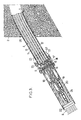
- Figure 3 shows an enlarged scale, in vertical section, a portion of said stay and the pylon which carries it.
- Figure 4 shows schematically and again in part a variant of a cable-stayed bridge according to the invention.
- the bridge to be equipped comprises an apron 1 suspended from at least one concrete pylon or pillar 2 using guy wires 3 anchored on this pylon and on this apron.
- the shrouds 3 are distributed on either side of the pylon 2, symmetrically with respect to its median transverse plane T by forming inverted V's.
- Each guy 3 is constituted by a plurality of independent strands 4, that is to say that can be mounted and tensioned independently of each other and even, in some cases, replaced in isolation.
- Each strand may be constituted by a large wire, but is preferably composed of a central core surrounded by a plurality of contiguous wires, generally six in number, wound in a helix around said core.
- each layer of guy lines extending on one side of a pylon includes twenty guy lines and each guy line is made up of twenty strands, the load supported by each strand is only 1 / 400th of the total, a proportion which is much lower than the tolerances or safety margins used for the construction of bridges.
- Each stay 3 forms an inverted V covering a pylon or at least a portion of this pylon and its upper portion, forming the top of the inverted V is rounded and rests on a curved surface 5 of the pylon forming "saddle".
- This saddle is here constituted by the base of a curved tunnel 6 hollowed out in the pylon 2 and extending in a curved arc downward, tunnel whose lower ends open respectively in the two transverse faces F and G of the pylon and are oriented obliquely downwards.
- the two feet of the shroud 3 are anchored on two blocks 7,8 which form part of the framework of the deck 1 or of suitable solid masses linked to the soil constituting the banks connected by the bridge.
- Each of the strands 4 constituting a stay 3 extends from one block 7 to the other 8 and passes successively through two intermediate anchor blocks 9, 10 located respectively near the two ends of the tunnel 6.
- the strands 4 are guided so as to remain parallel to each other and to be able to slide slightly relative to one another.
- Each of the two intermediate anchor blocks 9, 10 is arranged so as to provide a unidirectional anchoring in the sense that the strands 4 which pass through it can move away from the pylon 2, but not in the opposite direction.
- each crossing of a block 9.10 by a strand 4 is carried out in line with a frustoconical housing hollowed out in this block, converging in the direction of the pylon.
- This housing cooperates with a split frustoconical jaw 14 (FIG. 2) surrounding the strand concerned on the side, of the block, furthest from the pylon, said jaw preferably being urged into its housing by a spring 15 interposed between it and a retaining plate 16 itself crossed by the strands 4 and secured to the block concerned, at a small distance from this block, for example of the order of a centimeter, by small columns 17.
- a split frustoconical jaw 14 FIG. 2
- This housing cooperates with a split frustoconical jaw 14 (FIG. 2) surrounding the strand concerned on the side, of the block, furthest from the pylon, said jaw preferably being urged into its housing by a spring 15 interposed between it and a retaining plate 16 itself crossed by the strands 4 and secured to the block concerned, at a small distance from this block, for example of the order of a centimeter, by small columns 17.
- each of its constituent strands 4 is put in place by making it successively cross the two blocks 9 and 10, at least one of which is not yet made unidirectional: it suffices for this purpose, for the embodiment described by way of example, to maintain the jaw 14 concerned slightly apart from its housing in the corresponding block, by compressing the spring 15 which is associated with it if such a spring exists.
- the crossings of the two blocks 9 and 10 are then made unidirectional by the stretched strands, in particular by relaxing the springs 15 in the example above.
- each strand 4 which is disposed between the two blocks 9 and 10 remains stretched to a value which is at least its initial value and which can be gradually increased, irreversibly, to a maximum value.
- the curved section of the shroud which rests on the saddle 5 is sheltered from these alternations which generate fatigue due to the permanent maintenance of its tension.
- each strand is its most fragile portion because it is stressed not only in traction, but also in bending and possibly in friction against its support: the shelter from the fatigue of this curved portion therefore results in a greatly increased longevity for the stay.
- connection between these two segments A and B is carried out using an individual coupler 18 in the immediate vicinity of the corresponding block 9 or 10.
- the block 9 On its side opposite to the box 19, the block 9 is extended by a short sleeve 21 and the two axial ends of the tubular assembly composed of the box 19 and the sleeve 21 are constituted by cable glands 22, 23 crossed by tightly sealed by stranded portions of strands.
- the sheath enveloping the strand segment A is that previously designated by the reference 12, in which the strand concerned is housed with interposition of grease, and the sheath 24 relative to the strand segment B is directly extruded against it. ci, possibly with the interposition of a layer of wax or the like, said sheath being in particular made of a plastic material such as polyethylene or a polyamide.
- the various couplers 18 are preferably distributed according to a triangulated mesh equilateral extending over several floors and preferably over three floors.
- each individual coupler 18 is surrounded by a plurality of common portions of strands which are housed in external grooves of said coupler, the number of these grooves being generally six.
- the block 9 is not directly applied against the corresponding transverse face F of the pylon 2.
- This block 9 is here applied axially against one end of the jacket 11 lining the interior of the tunnel 6 hollowed out in the concrete of the pylon 2.
- This jacket 11 must therefore be designed so as to be able to transmit a certain axial force to the pylon 2.
- This transmission is favored by roughening the exterior surface, of the jacket 11, interior to the pylon, or even by bringing externally thereon suitable reliefs such as a wire 25 wound in a helix.
- the maximum value of the axial force that the jacket 11 must be able to transmit to the pylon 2 can be relatively low.
- the maximum value in question would correspond to the case where the entire oblique section of the shroud connected to block 9 would be dismantled: or in such a case, the maximum tension then applied to block 9 in the direction of the pylon would be applied not only to the jacket 11, but also on the whole of the hardened core of grout 13 filling the portions, of the volume inside the said jacket, which are not occupied by the greased sheathed strands 12, the core which is itself strongly adhered against the inside wall of the jacket 11 .
- the sleeve 21 described above is formed directly by one end of the jacket 11 itself, which end is welded to an end ring 26.
- the periphery of this ring 26 is fitted onto the block 9, crossed by the columns 17 above and extended by gussets 27 along the shirt 21.
- Said strand 4 also comprises an oblique rectilinear section 41 stretched between the deck 1 of the considered bridge and the top of the pylon 2 and a second section 42, non-rectilinear and embedded in concrete, these two sections being connected end to end at an intermediate anchoring device 28 bearing on the concrete structure portion in which said section 42 is embedded.
- this second section 42 is here drowned in a portion of the deck 1.
- this section 42 comprises a segment curved in an arc of a circle arranged in the extension of the oblique rectilinear section 41 and itself extended by a horizontal rectilinear segment extending in the longitudinal direction of the bridge.
- This horizontal segment is itself terminated by an anchoring device 29 of the usual type bearing horizontally against the deck 1.
- the intermediate anchoring device 28 As for the intermediate anchoring device 28, it bears against the bulkhead 1 in the opposite direction to the support of the anchoring device 29 so that these two supports make it possible to keep the section 42 under tension after its maximum tensioning initial.
- the intermediate anchoring device 28 is also designed so as to be able to block the strand 4 which passes through it in one direction, namely that oriented towards the deck 1.
- this coupler 32 is also intended like the previous one to be connected between they two constituent portions of the same strand 4, namely a greased sheathed portion comprising the section 42 and housed in a channel 33 hollowed out in the deck 1 with the interposition of a grout 34 and a portion corresponding essentially to the section 41 and formed of an element of strand protected by a plastic or similar sheath directly adhered around it.
- each strand 4 comprises a non-rectilinear portion constantly stretched embedded in the bridge deck, would be adopted in combination with those described with reference to Figures 1 to 3, for which each strand 4 comprises a curved portion constantly stretched resting on a saddle of a pylon.
Landscapes
- Engineering & Computer Science (AREA)
- Architecture (AREA)
- Civil Engineering (AREA)
- Structural Engineering (AREA)
- Bridges Or Land Bridges (AREA)
- Rod-Shaped Construction Members (AREA)
- Laying Of Electric Cables Or Lines Outside (AREA)
- Massaging Devices (AREA)
- Installation Of Indoor Wiring (AREA)
- Footwear And Its Accessory, Manufacturing Method And Apparatuses (AREA)
Applications Claiming Priority (2)
| Application Number | Priority Date | Filing Date | Title |
|---|---|---|---|
| FR9000274A FR2656883B1 (fr) | 1990-01-11 | 1990-01-11 | Perfectionnements aux ponts a haubans et plus particulierement a leurs haubans, pylones et tabliers. |
| FR9000274 | 1990-01-11 |
Publications (2)
| Publication Number | Publication Date |
|---|---|
| EP0437143A1 true EP0437143A1 (de) | 1991-07-17 |
| EP0437143B1 EP0437143B1 (de) | 1994-01-05 |
Family
ID=9392674
Family Applications (1)
| Application Number | Title | Priority Date | Filing Date |
|---|---|---|---|
| EP90403769A Expired - Lifetime EP0437143B1 (de) | 1990-01-11 | 1990-12-26 | Verbesserungen an Schrägseilbrücken und insbesondere an deren Seilen, Pfeilern und Fahrbahnen |
Country Status (8)
| Country | Link |
|---|---|
| EP (1) | EP0437143B1 (de) |
| AT (1) | ATE99754T1 (de) |
| BR (1) | BR9100091A (de) |
| DE (1) | DE69005807T2 (de) |
| DK (1) | DK0437143T3 (de) |
| ES (1) | ES2047888T3 (de) |
| FR (1) | FR2656883B1 (de) |
| PT (1) | PT96456B (de) |
Cited By (13)
| Publication number | Priority date | Publication date | Assignee | Title |
|---|---|---|---|---|
| DE19733822A1 (de) * | 1997-08-05 | 1999-02-11 | Dyckerhoff & Widmann Ag | Verfahren zum Einbauen und Spannen eines freigespannten Zugglieds und Vorrichtung zum Durchführen des Verfahrens |
| FR2790274A1 (fr) * | 1999-02-25 | 2000-09-01 | Bouygues Sa | Deviateur de cable de precontrainte exterieure d'un ouvrage en beton et ouvrages precontraints |
| EP1609911A1 (de) * | 2004-06-01 | 2005-12-28 | Dywidag-Systems International GmbH | Ausbildung eines korrosionsgeschützten Zugglieds im Bereich seines Eintritts in ein Bauwerk, insbesondere eines Schrägseils am Pylon einer Schrägseilbrücke |
| KR100792660B1 (ko) | 2005-11-09 | 2008-01-09 | 심준기 | 합성케이블을 이용한 교량시공방법 |
| WO2011116828A1 (en) * | 2010-03-26 | 2011-09-29 | Vsl International Ag | Sealing arrangement |
| WO2012076815A3 (fr) * | 2010-12-08 | 2012-08-09 | Soletanche Freyssinet | Dispositif de deviation d'un cable de structure tel qu'un hauban, et ouvrage ainsi equipe |
| US20130007966A1 (en) * | 2010-03-26 | 2013-01-10 | Vsl International Ag | Strand guiding device |
| WO2013139272A1 (zh) * | 2012-03-20 | 2013-09-26 | 柳州欧维姆机械股份有限公司 | 抗滑锁紧结构及带有该抗滑锁紧结构的斜拉桥索鞍 |
| CN108660923A (zh) * | 2018-03-22 | 2018-10-16 | 武汉船用机械有限责任公司 | 一种支座式转角索鞍 |
| WO2019020911A1 (fr) * | 2017-07-28 | 2019-01-31 | Soletanche Freyssinet | Ensemble amélioré comprenant un câble de structure et une selle |
| CN110629682A (zh) * | 2019-10-24 | 2019-12-31 | 德阳天元重工股份有限公司 | 一种悬索桥用顶推滑动摩擦副及其安装工艺 |
| CN116876346A (zh) * | 2023-08-24 | 2023-10-13 | 四川路桥华东建设有限责任公司 | 一种悬索桥锚碇弧形索股锚固系统 |
| CN117966626A (zh) * | 2024-01-18 | 2024-05-03 | 江阴法尔胜住电新材料有限公司 | 一种旧桥换索的主塔索鞍改造施工方法 |
Families Citing this family (3)
| Publication number | Priority date | Publication date | Assignee | Title |
|---|---|---|---|---|
| ES2589038B1 (es) * | 2015-05-04 | 2017-09-08 | Técnicas Del Pretensado Y Servicios Auxiliares, S.L. | Desviador para postesado exterior de viaductos y procedimiento para su fabricación |
| CN113700513B (zh) * | 2021-08-03 | 2024-05-24 | 武汉科技大学 | 一种复合式隧道锚碇结构 |
| CN116732895B (zh) * | 2023-07-14 | 2025-07-08 | 中铁大桥勘测设计院集团有限公司 | 一种水平式隧道锚碇主缆架设方法 |
Citations (3)
| Publication number | Priority date | Publication date | Assignee | Title |
|---|---|---|---|---|
| DE1658596A1 (de) * | 1967-02-09 | 1970-02-19 | Homberg Dr Ing Hellmut | Schraegseilbruecke |
| EP0073170A2 (de) * | 1981-08-21 | 1983-03-02 | Freyssinet International (Stup) | Bogenförmiges Verbindungsstück zwischen zwei geradlinigen Teilen eines gezogenen Seils |
| EP0323285B1 (de) * | 1987-11-25 | 1992-05-13 | Freyssinet International (Stup) | Schrägseile und deren Verankerung |
-
1990
- 1990-01-11 FR FR9000274A patent/FR2656883B1/fr not_active Expired - Lifetime
- 1990-12-26 DK DK90403769.4T patent/DK0437143T3/da active
- 1990-12-26 ES ES90403769T patent/ES2047888T3/es not_active Expired - Lifetime
- 1990-12-26 EP EP90403769A patent/EP0437143B1/de not_active Expired - Lifetime
- 1990-12-26 DE DE69005807T patent/DE69005807T2/de not_active Expired - Fee Related
- 1990-12-26 AT AT90403769T patent/ATE99754T1/de not_active IP Right Cessation
-
1991
- 1991-01-10 PT PT96456A patent/PT96456B/pt not_active IP Right Cessation
- 1991-01-10 BR BR919100091A patent/BR9100091A/pt not_active IP Right Cessation
Patent Citations (3)
| Publication number | Priority date | Publication date | Assignee | Title |
|---|---|---|---|---|
| DE1658596A1 (de) * | 1967-02-09 | 1970-02-19 | Homberg Dr Ing Hellmut | Schraegseilbruecke |
| EP0073170A2 (de) * | 1981-08-21 | 1983-03-02 | Freyssinet International (Stup) | Bogenförmiges Verbindungsstück zwischen zwei geradlinigen Teilen eines gezogenen Seils |
| EP0323285B1 (de) * | 1987-11-25 | 1992-05-13 | Freyssinet International (Stup) | Schrägseile und deren Verankerung |
Cited By (21)
| Publication number | Priority date | Publication date | Assignee | Title |
|---|---|---|---|---|
| DE19733822A1 (de) * | 1997-08-05 | 1999-02-11 | Dyckerhoff & Widmann Ag | Verfahren zum Einbauen und Spannen eines freigespannten Zugglieds und Vorrichtung zum Durchführen des Verfahrens |
| FR2790274A1 (fr) * | 1999-02-25 | 2000-09-01 | Bouygues Sa | Deviateur de cable de precontrainte exterieure d'un ouvrage en beton et ouvrages precontraints |
| EP1609911A1 (de) * | 2004-06-01 | 2005-12-28 | Dywidag-Systems International GmbH | Ausbildung eines korrosionsgeschützten Zugglieds im Bereich seines Eintritts in ein Bauwerk, insbesondere eines Schrägseils am Pylon einer Schrägseilbrücke |
| KR100792660B1 (ko) | 2005-11-09 | 2008-01-09 | 심준기 | 합성케이블을 이용한 교량시공방법 |
| US8650691B2 (en) * | 2010-03-26 | 2014-02-18 | Vsl International Ag | Strand guiding device |
| WO2011116828A1 (en) * | 2010-03-26 | 2011-09-29 | Vsl International Ag | Sealing arrangement |
| US20130007966A1 (en) * | 2010-03-26 | 2013-01-10 | Vsl International Ag | Strand guiding device |
| US8869476B2 (en) | 2010-03-26 | 2014-10-28 | Vsl International Ag | Sealing arrangement |
| RU2515660C1 (ru) * | 2010-03-26 | 2014-05-20 | Фсл Интернациональ Аг | Уплотняющая конструкция |
| WO2012076815A3 (fr) * | 2010-12-08 | 2012-08-09 | Soletanche Freyssinet | Dispositif de deviation d'un cable de structure tel qu'un hauban, et ouvrage ainsi equipe |
| CN103476993A (zh) * | 2010-12-08 | 2013-12-25 | 索列丹斯-弗莱西奈公司 | 使诸如拉索的结构缆索偏移的装置以及如此装备的建筑工程 |
| US8959692B2 (en) | 2010-12-08 | 2015-02-24 | Soletanche Freyssinet | Device for diverting a structural cable such as a stay and a structure so equipped |
| CN103476993B (zh) * | 2010-12-08 | 2016-04-06 | 索列丹斯-弗莱西奈公司 | 使诸如拉索的结构缆索偏移的装置以及如此装备的建筑工程 |
| RU2594246C2 (ru) * | 2010-12-08 | 2016-08-10 | Солетанш Фрейсине | Устройство для отклонения каната, такого как ванта, и оборудованный таким устройством строительный объект |
| WO2013139272A1 (zh) * | 2012-03-20 | 2013-09-26 | 柳州欧维姆机械股份有限公司 | 抗滑锁紧结构及带有该抗滑锁紧结构的斜拉桥索鞍 |
| WO2019020911A1 (fr) * | 2017-07-28 | 2019-01-31 | Soletanche Freyssinet | Ensemble amélioré comprenant un câble de structure et une selle |
| FR3069555A1 (fr) * | 2017-07-28 | 2019-02-01 | Soletanche Freyssinet | Ensemble ameliore comprenant un cable de structure et un dispositif de deviation |
| CN108660923A (zh) * | 2018-03-22 | 2018-10-16 | 武汉船用机械有限责任公司 | 一种支座式转角索鞍 |
| CN110629682A (zh) * | 2019-10-24 | 2019-12-31 | 德阳天元重工股份有限公司 | 一种悬索桥用顶推滑动摩擦副及其安装工艺 |
| CN116876346A (zh) * | 2023-08-24 | 2023-10-13 | 四川路桥华东建设有限责任公司 | 一种悬索桥锚碇弧形索股锚固系统 |
| CN117966626A (zh) * | 2024-01-18 | 2024-05-03 | 江阴法尔胜住电新材料有限公司 | 一种旧桥换索的主塔索鞍改造施工方法 |
Also Published As
| Publication number | Publication date |
|---|---|
| ATE99754T1 (de) | 1994-01-15 |
| DK0437143T3 (da) | 1994-04-25 |
| DE69005807D1 (de) | 1994-02-17 |
| BR9100091A (pt) | 1991-10-22 |
| ES2047888T3 (es) | 1994-03-01 |
| FR2656883A1 (fr) | 1991-07-12 |
| DE69005807T2 (de) | 1994-05-19 |
| PT96456A (pt) | 1991-10-15 |
| PT96456B (pt) | 1998-06-30 |
| FR2656883B1 (fr) | 1992-08-28 |
| EP0437143B1 (de) | 1994-01-05 |
Similar Documents
| Publication | Publication Date | Title |
|---|---|---|
| EP0437143B1 (de) | Verbesserungen an Schrägseilbrücken und insbesondere an deren Seilen, Pfeilern und Fahrbahnen | |
| EP0073170B1 (de) | Bogenförmiges Verbindungsstück zwischen zwei geradlinigen Teilen eines gezogenen Seils | |
| EP1131512B1 (de) | Verankerungsvorrichtung zum befestigen eines strukturkabels an einen bauteil | |
| EP0323285B1 (de) | Schrägseile und deren Verankerung | |
| CA2301102C (fr) | Procede et dispositif d'accrochage d'un element transmetteur de charge sur un cable, et pont suspendu comportant de tels dispositifs | |
| EP1144760A1 (de) | Anordnung und verfahren zum verbinden eines bauelements und einer kabelstruktur | |
| FR2661434A1 (fr) | Pont comprenant un tablier et au moins deux pylones, et son procede de construction. | |
| EP0518771B1 (de) | Verfahren und Vorrichtung zur Druckaufnahmeverstärkung von Beton und derart verstärkte Betonbauwerte | |
| FR2702782A1 (fr) | Perfectionnements aux procédés et dispositifs pour monter les haubans à torons multiples des ponts. | |
| EP1065317B1 (de) | Kabelaufhängung für eine Hängebrücke | |
| EP0465303B1 (de) | Verbesserungen an Schrägseilbrücken und insbesondere an deren Seilen und Pfeilern | |
| EP0687774B1 (de) | Vorrichtung zum waagerecht Verbinden von Leitschienen oder dergleichen Teilen | |
| FR2806428A1 (fr) | Procede pour ancrer un nouveau cable a un massif d'ancrage preexistant sur lequel est deja ancre un cable d'origine | |
| FR2858987A1 (fr) | Procede de montage d'un hauban | |
| FR2791373A1 (fr) | Dispositif pour fixer un cable de structure a un element de construction | |
| FR2757235A1 (fr) | Procede et dispositif d'amortissement des vibrations transversales de cables de haubanage | |
| FR2545130A1 (fr) | Dispositif d'ancrage d'un cable de precontrainte en un point intermediaire d'un ouvrage en beton | |
| EP2594700B1 (de) | Kabel für Bauwerke und Verankerungsverfahren für solches Kabel | |
| EP1159490A1 (de) | Mantel für parallellitzenseil sowie schrägseil mit einem solchen mantel | |
| FR2691737A1 (fr) | Perfectionnements aux dispositifs pour effectuer des ancrages intermédiaires sur des câbles de précontrainte. | |
| FR3121456A1 (fr) | Procede pour ôter une armature d’un cable de structure et systeme associe | |
| FR2739112A1 (fr) | Ouvrage de genie civil suspendu et son procede de construction | |
| FR2642449A1 (fr) | Perfectionnements aux ponts a haubans et plus particulierement a leurs pylones et haubans | |
| EP1393790A1 (de) | Progressive Brems- und Anhaltevorrichtung für einen Laufwagen oder Entsprechendes | |
| FR3070993A1 (fr) | Dispositif de liaison pour arcs de soutien d’une toile de couverture |
Legal Events
| Date | Code | Title | Description |
|---|---|---|---|
| PUAI | Public reference made under article 153(3) epc to a published international application that has entered the european phase |
Free format text: ORIGINAL CODE: 0009012 |
|
| AK | Designated contracting states |
Kind code of ref document: A1 Designated state(s): AT BE CH DE DK ES GB GR IT LI LU NL SE |
|
| 17P | Request for examination filed |
Effective date: 19910909 |
|
| 17Q | First examination report despatched |
Effective date: 19921221 |
|
| GRAA | (expected) grant |
Free format text: ORIGINAL CODE: 0009210 |
|
| AK | Designated contracting states |
Kind code of ref document: B1 Designated state(s): AT BE CH DE DK ES GB GR IT LI LU NL SE |
|
| REF | Corresponds to: |
Ref document number: 99754 Country of ref document: AT Date of ref document: 19940115 Kind code of ref document: T |
|
| ITF | It: translation for a ep patent filed | ||
| GBT | Gb: translation of ep patent filed (gb section 77(6)(a)/1977) |
Effective date: 19940114 |
|
| REF | Corresponds to: |
Ref document number: 69005807 Country of ref document: DE Date of ref document: 19940217 |
|
| REG | Reference to a national code |
Ref country code: ES Ref legal event code: FG2A Ref document number: 2047888 Country of ref document: ES Kind code of ref document: T3 |
|
| REG | Reference to a national code |
Ref country code: GR Ref legal event code: FG4A Free format text: 3010381 |
|
| REG | Reference to a national code |
Ref country code: DK Ref legal event code: T3 |
|
| PLBE | No opposition filed within time limit |
Free format text: ORIGINAL CODE: 0009261 |
|
| STAA | Information on the status of an ep patent application or granted ep patent |
Free format text: STATUS: NO OPPOSITION FILED WITHIN TIME LIMIT |
|
| 26N | No opposition filed | ||
| EAL | Se: european patent in force in sweden |
Ref document number: 90403769.4 |
|
| PGFP | Annual fee paid to national office [announced via postgrant information from national office to epo] |
Ref country code: NL Payment date: 19951117 Year of fee payment: 6 |
|
| PGFP | Annual fee paid to national office [announced via postgrant information from national office to epo] |
Ref country code: DK Payment date: 19951124 Year of fee payment: 6 |
|
| PGFP | Annual fee paid to national office [announced via postgrant information from national office to epo] |
Ref country code: AT Payment date: 19951127 Year of fee payment: 6 |
|
| PGFP | Annual fee paid to national office [announced via postgrant information from national office to epo] |
Ref country code: ES Payment date: 19951128 Year of fee payment: 6 |
|
| PGFP | Annual fee paid to national office [announced via postgrant information from national office to epo] |
Ref country code: GR Payment date: 19951130 Year of fee payment: 6 |
|
| PGFP | Annual fee paid to national office [announced via postgrant information from national office to epo] |
Ref country code: SE Payment date: 19951218 Year of fee payment: 6 |
|
| PGFP | Annual fee paid to national office [announced via postgrant information from national office to epo] |
Ref country code: GB Payment date: 19951219 Year of fee payment: 6 |
|
| PGFP | Annual fee paid to national office [announced via postgrant information from national office to epo] |
Ref country code: CH Payment date: 19951227 Year of fee payment: 6 |
|
| PGFP | Annual fee paid to national office [announced via postgrant information from national office to epo] |
Ref country code: DE Payment date: 19951229 Year of fee payment: 6 |
|
| PGFP | Annual fee paid to national office [announced via postgrant information from national office to epo] |
Ref country code: LU Payment date: 19960101 Year of fee payment: 6 |
|
| PGFP | Annual fee paid to national office [announced via postgrant information from national office to epo] |
Ref country code: BE Payment date: 19960117 Year of fee payment: 6 |
|
| PG25 | Lapsed in a contracting state [announced via postgrant information from national office to epo] |
Ref country code: LU Free format text: LAPSE BECAUSE OF NON-PAYMENT OF DUE FEES Effective date: 19961226 Ref country code: GB Effective date: 19961226 Ref country code: DK Effective date: 19961226 Ref country code: AT Effective date: 19961226 |
|
| REG | Reference to a national code |
Ref country code: DK Ref legal event code: EBP |
|
| PG25 | Lapsed in a contracting state [announced via postgrant information from national office to epo] |
Ref country code: SE Effective date: 19961227 Ref country code: ES Free format text: LAPSE BECAUSE OF EXPIRATION OF PROTECTION Effective date: 19961227 |
|
| PG25 | Lapsed in a contracting state [announced via postgrant information from national office to epo] |
Ref country code: LI Effective date: 19961231 Ref country code: CH Effective date: 19961231 Ref country code: BE Effective date: 19961231 |
|
| REG | Reference to a national code |
Ref country code: ES Ref legal event code: GD2A Effective date: 19970331 |
|
| BERE | Be: lapsed |
Owner name: FREYSSINET INTERNATIONAL (STUP) Effective date: 19961231 |
|
| PG25 | Lapsed in a contracting state [announced via postgrant information from national office to epo] |
Ref country code: GR Free format text: THE PATENT HAS BEEN ANNULLED BY A DECISION OF A NATIONAL AUTHORITY Effective date: 19970630 |
|
| PG25 | Lapsed in a contracting state [announced via postgrant information from national office to epo] |
Ref country code: NL Effective date: 19970701 |
|
| REG | Reference to a national code |
Ref country code: GR Ref legal event code: MM2A Free format text: 3010381 |
|
| GBPC | Gb: european patent ceased through non-payment of renewal fee |
Effective date: 19961226 |
|
| REG | Reference to a national code |
Ref country code: CH Ref legal event code: PL |
|
| NLV4 | Nl: lapsed or anulled due to non-payment of the annual fee |
Effective date: 19970701 |
|
| PG25 | Lapsed in a contracting state [announced via postgrant information from national office to epo] |
Ref country code: DE Effective date: 19970902 |
|
| EUG | Se: european patent has lapsed |
Ref document number: 90403769.4 |
|
| REG | Reference to a national code |
Ref country code: ES Ref legal event code: FD2A Effective date: 20010201 |
|
| PG25 | Lapsed in a contracting state [announced via postgrant information from national office to epo] |
Ref country code: IT Free format text: LAPSE BECAUSE OF NON-PAYMENT OF DUE FEES Effective date: 20051226 |