EP0437150B1 - Dispositif de commande pour une boîte de vitesses automatique pour véhicules automobiles - Google Patents
Dispositif de commande pour une boîte de vitesses automatique pour véhicules automobiles Download PDFInfo
- Publication number
- EP0437150B1 EP0437150B1 EP90403815A EP90403815A EP0437150B1 EP 0437150 B1 EP0437150 B1 EP 0437150B1 EP 90403815 A EP90403815 A EP 90403815A EP 90403815 A EP90403815 A EP 90403815A EP 0437150 B1 EP0437150 B1 EP 0437150B1
- Authority
- EP
- European Patent Office
- Prior art keywords
- lever
- shift
- pivot shaft
- axis
- bell crank
- Prior art date
- Legal status (The legal status is an assumption and is not a legal conclusion. Google has not performed a legal analysis and makes no representation as to the accuracy of the status listed.)
- Expired - Lifetime
Links
Images

Classifications
-
- F—MECHANICAL ENGINEERING; LIGHTING; HEATING; WEAPONS; BLASTING
- F16—ENGINEERING ELEMENTS AND UNITS; GENERAL MEASURES FOR PRODUCING AND MAINTAINING EFFECTIVE FUNCTIONING OF MACHINES OR INSTALLATIONS; THERMAL INSULATION IN GENERAL
- F16H—GEARING
- F16H59/00—Control inputs to control units of change-speed- or reversing-gearings for conveying rotary motion
- F16H59/02—Selector apparatus
- F16H59/08—Range selector apparatus
- F16H59/10—Range selector apparatus comprising levers
-
- B—PERFORMING OPERATIONS; TRANSPORTING
- B60—VEHICLES IN GENERAL
- B60K—ARRANGEMENT OR MOUNTING OF PROPULSION UNITS OR OF TRANSMISSIONS IN VEHICLES; ARRANGEMENT OR MOUNTING OF PLURAL DIVERSE PRIME-MOVERS IN VEHICLES; AUXILIARY DRIVES FOR VEHICLES; INSTRUMENTATION OR DASHBOARDS FOR VEHICLES; ARRANGEMENTS IN CONNECTION WITH COOLING, AIR INTAKE, GAS EXHAUST OR FUEL SUPPLY OF PROPULSION UNITS IN VEHICLES
- B60K20/00—Arrangement or mounting of change-speed gearing control devices in vehicles
- B60K20/02—Arrangement or mounting of change-speed gearing control devices in vehicles of initiating means
- B60K20/04—Arrangement or mounting of change-speed gearing control devices in vehicles of initiating means floor mounted
-
- Y—GENERAL TAGGING OF NEW TECHNOLOGICAL DEVELOPMENTS; GENERAL TAGGING OF CROSS-SECTIONAL TECHNOLOGIES SPANNING OVER SEVERAL SECTIONS OF THE IPC; TECHNICAL SUBJECTS COVERED BY FORMER USPC CROSS-REFERENCE ART COLLECTIONS [XRACs] AND DIGESTS
- Y10—TECHNICAL SUBJECTS COVERED BY FORMER USPC
- Y10T—TECHNICAL SUBJECTS COVERED BY FORMER US CLASSIFICATION
- Y10T74/00—Machine element or mechanism
- Y10T74/20—Control lever and linkage systems
- Y10T74/20012—Multiple controlled elements
- Y10T74/20018—Transmission control
- Y10T74/20085—Restriction of shift, gear selection, or gear engagement
- Y10T74/20098—Separate actuator to disengage restrictor
-
- Y—GENERAL TAGGING OF NEW TECHNOLOGICAL DEVELOPMENTS; GENERAL TAGGING OF CROSS-SECTIONAL TECHNOLOGIES SPANNING OVER SEVERAL SECTIONS OF THE IPC; TECHNICAL SUBJECTS COVERED BY FORMER USPC CROSS-REFERENCE ART COLLECTIONS [XRACs] AND DIGESTS
- Y10—TECHNICAL SUBJECTS COVERED BY FORMER USPC
- Y10T—TECHNICAL SUBJECTS COVERED BY FORMER US CLASSIFICATION
- Y10T74/00—Machine element or mechanism
- Y10T74/20—Control lever and linkage systems
- Y10T74/20012—Multiple controlled elements
- Y10T74/20018—Transmission control
- Y10T74/2014—Manually operated selector [e.g., remotely controlled device, lever, push button, rotary dial, etc.]
-
- Y—GENERAL TAGGING OF NEW TECHNOLOGICAL DEVELOPMENTS; GENERAL TAGGING OF CROSS-SECTIONAL TECHNOLOGIES SPANNING OVER SEVERAL SECTIONS OF THE IPC; TECHNICAL SUBJECTS COVERED BY FORMER USPC CROSS-REFERENCE ART COLLECTIONS [XRACs] AND DIGESTS
- Y10—TECHNICAL SUBJECTS COVERED BY FORMER USPC
- Y10T—TECHNICAL SUBJECTS COVERED BY FORMER US CLASSIFICATION
- Y10T74/00—Machine element or mechanism
- Y10T74/20—Control lever and linkage systems
- Y10T74/20396—Hand operated
- Y10T74/20402—Flexible transmitter [e.g., Bowden cable]
- Y10T74/2042—Flexible transmitter [e.g., Bowden cable] and hand operator
-
- Y—GENERAL TAGGING OF NEW TECHNOLOGICAL DEVELOPMENTS; GENERAL TAGGING OF CROSS-SECTIONAL TECHNOLOGIES SPANNING OVER SEVERAL SECTIONS OF THE IPC; TECHNICAL SUBJECTS COVERED BY FORMER USPC CROSS-REFERENCE ART COLLECTIONS [XRACs] AND DIGESTS
- Y10—TECHNICAL SUBJECTS COVERED BY FORMER USPC
- Y10T—TECHNICAL SUBJECTS COVERED BY FORMER US CLASSIFICATION
- Y10T74/00—Machine element or mechanism
- Y10T74/20—Control lever and linkage systems
- Y10T74/20576—Elements
- Y10T74/20636—Detents
- Y10T74/20672—Lever engaging rack
- Y10T74/20696—Finger lever release
- Y10T74/20702—Slidable
Definitions
- the present invention relates generally to a shift lever construction for an automatic transmission and more specifically to a shift lever construction which features an improved shift feeling.
- JP-U-60-195225 discloses a shift device as specified in the preamble of claim 1.
- a bell crank lever is used to operatively interconnect a transmission control cable with a shift lever.
- the bell crank lever is pivoted about an axis which is located at essentially the same level as the axis about which the shift lever is pivotal.
- Connection between the shift lever and the bell crank lever is achieved by means of a pin which projects from one side of a shaft which forms part of a detent mechanism, and an elongate slot formed in one end of the bell crank lever.
- bell crank lever is pivotally mounted on a plate which forms part of the detent mechanism and in which detent recesses are formed. This facilitates the accurate assembly of the device. Further, as the bell crank lever is pivoted at substantially the same height as the pivot shaft of the shift lever and arranged above the bottom wall of the base bracket, a lever effect equal to that of the conventional construction is achieved. Furthermore, since there is no need for an intermediate shaft, reduction in play and cost are also achieved.
- the present invention relates to a shift device for an automatic transmission comprising : a base bracket with a base member from which essentially vertical side wall extends, the base bracket being adapted for connection to a vehicle body ; a shift lever ; a pivot shaft mounted pivotally with respect to the side wall of the base bracket and providing a first axis, said shift lever being mounted on the pivot shaft so as to be pivotal about said axis ; a lever member mounted on the pivot shaft so as to be rotatable with the shift lever ; a position plate arranged to extend parallel with the direction in which the shift lever is pivotal, the position plate having first positioning recesses with which a position pin operatively mounted on the shift lever is detachably engageable ; and lever means for transmitting an operating force from the shift lever to a control cable of the automatic transmission, said lever means being pivotal about a second axis which is located at essentially the same level as said first axis and arranged above a bottom wall of the base bracket, characterized in that said position
- the invention is also characterized in that said lever means comprises a bell crank lever pivotally supported on said position plate, said bell crank lever having one end operatively connected with the transmission control cable and another end operatively connected with said lever member.
- the operative connection between the other end of said bell crank lever and the lever member includes an elongate slot in one of said bell crank lever and said lever member ; and a pin which is rigid with the other of said bell crank lever and said lever member.
- said shift lever and said lever member are respectively rigid with the pivot shaft being rotatably mounted to the side wall of the base bracket.
- said lever means is arranged to pivot about said second axis in a first rotational direction when said shift lever pivots about said first axis in a second rotational direction which is opposite to said first rotational direction.
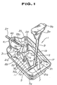
- Figs. 1 and 2 show an embodiment of the present invention.
- Fig. 1 is a perspective view and
- Fig. 2 is a vertically sectioned view of the device of Fig. 1.
- Figs. 1 and 2 show an embodiment of the present invention.
- Designated by numeral 1 is a shift lever device for an automatic transmission.
- the shift lever device 1 comprises a shift lever 9 which is supported by a pivot shaft 7 on the vertical side wall 5a of a pan-shaped base bracket 5 fixed to a floor panel 3 of a vehicle body.
- a detent mechanism includes a lever member 11 which is pivotally movable in accordance with the pivotal movement of the shift lever 9.
- the lever member 11 is rigid with and extends from the pivot shaft 7.
- the detent mechanism further includes a position plate 21 which extends along a plane which is normal to the axis about which the shift lever rotates, i.e. parallel with the direction in which the shift lever 9 is movable.
- the position plate 21 has front and rear flanges 21a and 21b secured to the fore and aft vertical end wall 5a of the base bracket 5.
- the plate 21 is formed with notches 19 and 23.
- a position pin 17 which is vertically movable along an elongate slot formed in the shift lever 9 and constantly biased upward by a spring 15 is detachably engageable or receivable in the notches 19 of the position plate 21.
- a check ball 25 is supported on a free end 11a of the lever member 11 and is detachably engageable with check portions defined by the notches 23.
- a force transmission means 29 is arranged such that, upon pivotal movement of the lever member 11, force is transmitted to control cable 27 of the automatic transmission (not shown).
- a pivot shaft 31 of a force transmission means 29 is positioned at approximately the same height as the pivot shaft 7 of the shift lever 9 and arranged above a bottom wall 5b of the base bracket 5.
- the position pin 17 is moved downwardly in a manner which disengages the same from the neutral position (N), drive position (D), etc. notches or positioning recesses 19 of the position plate 21.
- the position pin 17 moves upward under the bias of spring 15 and engages the notches 19 in a newly selected position (for example, parking position (P), second position (S), etc.,).
- the transmission means 29 comprises a bellcrank lever 33 which is pivotally supported by the pivot shaft 31.
- This shaft 31 is supported by the position plate 21.
- One end portion 33a of the lever 33 is formed with an elongate slot 37 in and along which a pin 35, which projects from a side portion of the lever member 11, is slidably engaged.
- the other end portion 33b of the supporting plate 33 is formed with an opening 39 to which the control cable 27 is pivotally connected.
- a grommet 43 which supports the control cable 27, is fitted in a recess 41 formed in the vertical wall 5a of the base bracket 5.
- the pivot shaft 31 of the transmission means 29 is positioned at substantially the same height as the pivot shaft 7 of the shift lever 9, and arranged above the bottom wall 5b of the base bracket 5, a lever effect equal to that of the conventional construction is obtained. Furthermore, since the pivot shaft 31 is connected to the position plate 21, the ease and precision with which assembly can be carried out is increased.
- the depth of the device is minimized and thus alleviating road clearance related design problems.
Landscapes
- Engineering & Computer Science (AREA)
- Mechanical Engineering (AREA)
- General Engineering & Computer Science (AREA)
- Chemical & Material Sciences (AREA)
- Combustion & Propulsion (AREA)
- Transportation (AREA)
- Arrangement Or Mounting Of Control Devices For Change-Speed Gearing (AREA)
- Control Of Transmission Device (AREA)
- Gear-Shifting Mechanisms (AREA)
Claims (5)
- Un dispositif de changement de rapport pour une transmission automatique, comprenant :
une console de base (5) avec un élément de base depuis lequel s'étend une paroi latérale essentiellement verticale (5a), la console de base étant adaptée à la liaison avec une caisse de véhicule (3) ;
un levier de changement de rapport (9) ;
un arbre de pivotement (7) monté sur la paroi latérale (5a) de ladite console de base (5) et procurant à un premier axe, ledit levier de changement de rapport (9) étant monté sur l'arbre de pivotement (7) de façon à pouvoir pivoter autour dudit premier axe ;
un élément formant levier (11) monté sur l'arbre de pivotement (7) de façon à pouvoir tourner avec le levier de changement de rapport (9) ;
une plaque de positionnement (21) agencée pour s'étendre parallèlement à la direction dans laquelle le levier de changement de rapport (9) peut pivoter, la plaque de positionnement (21) ayant de premiers évidements de positionnement (19) avec lesquels peut entrer amoviblement en prise une cheville de positionnement (17) fonctionnellement montée sur ledit levier de changement de rapport (9) ; et
des moyens formant levier (29) pour transmettre une force d'actionnement depuis ledit levier de changement de rapport (9) à un câble de commande (27) de la transmission automatique, lesdits moyens formant levier pouvant pivoter autour d'un second axe qui est situé essentiellement au même niveau que ledit premier axe de l'arbre de pivotement (7) et agencé au-dessus d'une paroi inférieure de la console de base (5), caractérisé en ce que ladite plaque de positionnement (21) comprend en outre de seconds évidements de positionnement (23) avec lesquels peut amoviblement entrer en prise une bille de retenue (25) supportée sur une extrémité libre (11a) de l'élément formant levier (11). - Un dispositif de changement de rapport tel que revendiqué dans la revendication 1, dans lequel ledit moyen formant levier (29) comprend :
un levier coudé (33) supporté de façon pivotante sur ladite plaque de positionnement (21), ledit levier coudé ayant une extrémité (33b) fonctionnellement reliée au câble de commande de transmission et une autre extrémité (33a) fonctionnellement réliée audit élément formant levier (11). - Un dispositif de changement de rapport tel que revendiqué dans la revendication 2, dans lequel la liaison fonctionnelle entre l'autre extrémité (33a) dudit levier coudé (33) et l'élément formant levier (11) consiste en :
une fente allongée (37) dans l'une des deux pièces formant respectivement ledit levier coudé (33) et ledit élément formant levier (15) ; et
une cheville (35) qui est solidaire de l'autre pièce formant respectivement ledit levier coudé (33) et ledit élément formant levier (11). - Un dispositif de changement de rapport tel que revendiqué dans l'une quelconque des revendications 1 à 3, dans lequel ledit levier de changement de rapport (9) et ledit élément formant levier (11) sont respectivement solidaires de l'arbre de pivotement (7), ledit arbre de pivotement (7) étant monté de façon tournante sur la paroi latérale (5a) de la console de base (5).
- Un dispositif de changement de vitesses tel que revendiqué dans l'une quelconque des revendications 1 à 4, dans lequel ledit moyen formant levier (29) est agencé pour pivoter autour dudit second axe dans un premier sens de rotation lorsque ledit levier de changement de rapport (9) pivote autour dudit premier axe dans un second sens de rotation qui est opposé audit premier sens de rotation.
Applications Claiming Priority (2)
| Application Number | Priority Date | Filing Date | Title |
|---|---|---|---|
| JP2004360A JP2945427B2 (ja) | 1990-01-10 | 1990-01-10 | 自動変速機のシフト装置 |
| JP4360/90 | 1990-01-10 |
Publications (2)
| Publication Number | Publication Date |
|---|---|
| EP0437150A1 EP0437150A1 (fr) | 1991-07-17 |
| EP0437150B1 true EP0437150B1 (fr) | 1994-03-02 |
Family
ID=11582214
Family Applications (1)
| Application Number | Title | Priority Date | Filing Date |
|---|---|---|---|
| EP90403815A Expired - Lifetime EP0437150B1 (fr) | 1990-01-10 | 1990-12-31 | Dispositif de commande pour une boîte de vitesses automatique pour véhicules automobiles |
Country Status (4)
| Country | Link |
|---|---|
| US (1) | US5156061A (fr) |
| EP (1) | EP0437150B1 (fr) |
| JP (1) | JP2945427B2 (fr) |
| DE (1) | DE69007063T2 (fr) |
Families Citing this family (13)
| Publication number | Priority date | Publication date | Assignee | Title |
|---|---|---|---|---|
| US5339705A (en) * | 1991-03-07 | 1994-08-23 | Nissan Motor Co., Ltd. | Shift device for automatic transmission |
| JPH05312248A (ja) * | 1992-05-08 | 1993-11-22 | Nissan Motor Co Ltd | シフトレバー装置 |
| US5398565A (en) * | 1993-02-04 | 1995-03-21 | Grand Haven Stamped Products Company, A Division Of Jsj Corporation | Shift lever assembly |
| DE4305015C1 (de) * | 1993-02-18 | 1994-03-10 | Ford Werke Ag | Wählhebelanordnung für ein automatisches Getriebe eines Kraftfahrzeuges |
| GB9322836D0 (en) * | 1993-11-05 | 1993-12-22 | Rover Group | A selector mechanism for a vehicle transmission |
| GB2298465B (en) * | 1993-11-05 | 1997-10-29 | Rover Group | A selector mechanism for a vehicle transmission |
| JP3586722B2 (ja) * | 1993-11-15 | 2004-11-10 | コングスバリ オートモーティブ アーベー | 操作装置 |
| US5662004A (en) * | 1995-01-19 | 1997-09-02 | Grand Haven Stamped Products, Div. Of Jsj Corporation | Vehicle shift cable connection |
| US5738303A (en) † | 1995-05-15 | 1998-04-14 | The Boeing Company | Mechanism for arming, disarming and activating airplane emergency slide evacuation systems |
| US5785626A (en) * | 1996-03-05 | 1998-07-28 | Grand Haven Stamped Products Division Of Jsj Corporation | Shifter with cable adjustable mechanism |
| US6282974B1 (en) * | 1996-03-12 | 2001-09-04 | Fujikiko Kabushiki Kaisha | Operating apparatus for automatic transmission |
| DE19711237A1 (de) * | 1996-12-21 | 1998-07-02 | Deere & Co | Schalteinrichtung für ein Getriebe |
| SE512356C2 (sv) * | 1998-07-29 | 2000-03-06 | Volvo Lastvagnar Ab | Växlingsmekanism för en fordonsväxellåda |
Family Cites Families (9)
| Publication number | Priority date | Publication date | Assignee | Title |
|---|---|---|---|---|
| US3766799A (en) * | 1972-11-17 | 1973-10-23 | Gen Motors Corp | Gearshift mechanism |
| US3998109A (en) * | 1975-09-15 | 1976-12-21 | General Motors Corporation | Automatic transmission control linkage |
| JPS6012165Y2 (ja) * | 1979-12-21 | 1985-04-20 | 日産自動車株式会社 | 自動変速機の操作装置 |
| US4566349A (en) * | 1983-10-06 | 1986-01-28 | Alofs Manufacturing Company | Chatterless shifter |
| JPS60195225A (ja) * | 1984-03-15 | 1985-10-03 | Mitani Sekisan Kk | 杭打用ハンマ− |
| US4649766A (en) * | 1985-02-15 | 1987-03-17 | Kiekhaefer Aeromarine, Inc. | Remote control apparatus |
| JPH069939B2 (ja) * | 1986-11-29 | 1994-02-09 | いすゞ自動車株式会社 | 自動変速機のシフトレバ装置 |
| DE3714285A1 (de) * | 1987-04-29 | 1988-11-10 | Ford Werke Ag | Waehlhebelanordnung fuer ein kraftfahrzeug-automatik-getriebe |
| DE3744761C2 (de) * | 1987-08-07 | 1996-03-14 | Audi Ag | Betätigungsvorrichtung für ein automatisches Getriebe in einem Kraftfahrzeug |
-
1990
- 1990-01-10 JP JP2004360A patent/JP2945427B2/ja not_active Expired - Lifetime
- 1990-12-31 DE DE69007063T patent/DE69007063T2/de not_active Expired - Fee Related
- 1990-12-31 EP EP90403815A patent/EP0437150B1/fr not_active Expired - Lifetime
-
1991
- 1991-01-02 US US07/636,847 patent/US5156061A/en not_active Expired - Fee Related
Also Published As
| Publication number | Publication date |
|---|---|
| JP2945427B2 (ja) | 1999-09-06 |
| US5156061A (en) | 1992-10-20 |
| DE69007063D1 (de) | 1994-04-07 |
| EP0437150A1 (fr) | 1991-07-17 |
| JPH03208733A (ja) | 1991-09-11 |
| DE69007063T2 (de) | 1994-10-06 |
Similar Documents
| Publication | Publication Date | Title |
|---|---|---|
| EP0437150B1 (fr) | Dispositif de commande pour une boîte de vitesses automatique pour véhicules automobiles | |
| EP0662203B1 (fr) | Dispositif de changement de vitesse manuel | |
| US5996438A (en) | Adjustable accelerator pedal | |
| US4245521A (en) | Manual transmission shifter for operating a transmission with flexible cables | |
| EP0754884A3 (fr) | Dispositif de commande de changement de rapport pour transmission dans un véhicule automobile | |
| JPH07190179A (ja) | トランスミッションのシフトレバー組立体 | |
| GB2100374A (en) | Column-shift gear-selectors | |
| EP1375981B1 (fr) | Dispositif de passage pour transmission automatique | |
| US5417126A (en) | Selector lever arrangement for an automatic transmission of a motor vehicle | |
| US4422690A (en) | Seat position control mechanism | |
| USRE31451E (en) | Manual transmission shifter for operating a transmission with elongated actuators such as flexible cables | |
| US4991460A (en) | Shift lever device for automatic transmission | |
| US5187998A (en) | Shift lever for automatic transmission | |
| US6619155B2 (en) | Adjustable pedal apparatus | |
| US3869279A (en) | Accelerator Pedal Assembly | |
| EP0575861B2 (fr) | Système de commande de boíte de vitesse d'un véhicule à moteur | |
| US5339705A (en) | Shift device for automatic transmission | |
| US20070151407A1 (en) | Adjustable pedal assembly | |
| JP2004521406A (ja) | 車両用調節可能ペダル装置 | |
| US4524634A (en) | Transmission shifting mechanism | |
| US4157740A (en) | Remote shift control for a tilt cab truck | |
| US6167772B1 (en) | Arrangement for attaching gearshift assembly and method of assembling the same | |
| US7832305B2 (en) | Adjustable pedal system with low brake ratio change | |
| JPH1067244A (ja) | 変速機操作レバー | |
| US3550551A (en) | Transmission control and indicator apparatus |
Legal Events
| Date | Code | Title | Description |
|---|---|---|---|
| PUAI | Public reference made under article 153(3) epc to a published international application that has entered the european phase |
Free format text: ORIGINAL CODE: 0009012 |
|
| 17P | Request for examination filed |
Effective date: 19901231 |
|
| AK | Designated contracting states |
Kind code of ref document: A1 Designated state(s): DE GB |
|
| 17Q | First examination report despatched |
Effective date: 19920622 |
|
| GRAA | (expected) grant |
Free format text: ORIGINAL CODE: 0009210 |
|
| AK | Designated contracting states |
Kind code of ref document: B1 Designated state(s): DE GB |
|
| REF | Corresponds to: |
Ref document number: 69007063 Country of ref document: DE Date of ref document: 19940407 |
|
| PLBE | No opposition filed within time limit |
Free format text: ORIGINAL CODE: 0009261 |
|
| STAA | Information on the status of an ep patent application or granted ep patent |
Free format text: STATUS: NO OPPOSITION FILED WITHIN TIME LIMIT |
|
| 26N | No opposition filed | ||
| REG | Reference to a national code |
Ref country code: GB Ref legal event code: IF02 |
|
| PGFP | Annual fee paid to national office [announced via postgrant information from national office to epo] |
Ref country code: GB Payment date: 20020102 Year of fee payment: 12 |
|
| PGFP | Annual fee paid to national office [announced via postgrant information from national office to epo] |
Ref country code: DE Payment date: 20020109 Year of fee payment: 12 |
|
| PG25 | Lapsed in a contracting state [announced via postgrant information from national office to epo] |
Ref country code: GB Free format text: LAPSE BECAUSE OF NON-PAYMENT OF DUE FEES Effective date: 20021231 |
|
| PG25 | Lapsed in a contracting state [announced via postgrant information from national office to epo] |
Ref country code: DE Free format text: LAPSE BECAUSE OF NON-PAYMENT OF DUE FEES Effective date: 20030701 |
|
| GBPC | Gb: european patent ceased through non-payment of renewal fee |
Effective date: 20021231 |