EP0437189B1 - Wasserstandsregelvorrichtung für Geschirrspülmaschinen - Google Patents
Wasserstandsregelvorrichtung für Geschirrspülmaschinen Download PDFInfo
- Publication number
- EP0437189B1 EP0437189B1 EP90850376A EP90850376A EP0437189B1 EP 0437189 B1 EP0437189 B1 EP 0437189B1 EP 90850376 A EP90850376 A EP 90850376A EP 90850376 A EP90850376 A EP 90850376A EP 0437189 B1 EP0437189 B1 EP 0437189B1
- Authority
- EP
- European Patent Office
- Prior art keywords
- chamber
- liquid
- tub
- heating source
- opening
- Prior art date
- Legal status (The legal status is an assumption and is not a legal conclusion. Google has not performed a legal analysis and makes no representation as to the accuracy of the status listed.)
- Expired - Lifetime
Links
- 238000010438 heat treatment Methods 0.000 claims abstract description 20
- 239000007788 liquid Substances 0.000 claims abstract description 18
- 238000010792 warming Methods 0.000 claims abstract description 3
- XLYOFNOQVPJJNP-UHFFFAOYSA-N water Substances O XLYOFNOQVPJJNP-UHFFFAOYSA-N 0.000 description 5
- 238000004851 dishwashing Methods 0.000 description 4
- 239000007921 spray Substances 0.000 description 3
- 238000000034 method Methods 0.000 description 2
- 238000004140 cleaning Methods 0.000 description 1
- 239000000110 cooling liquid Substances 0.000 description 1
- 238000013021 overheating Methods 0.000 description 1
- 239000002245 particle Substances 0.000 description 1
- 238000005192 partition Methods 0.000 description 1
Images

Classifications
-
- A—HUMAN NECESSITIES
- A47—FURNITURE; DOMESTIC ARTICLES OR APPLIANCES; COFFEE MILLS; SPICE MILLS; SUCTION CLEANERS IN GENERAL
- A47L—DOMESTIC WASHING OR CLEANING; SUCTION CLEANERS IN GENERAL
- A47L15/00—Washing or rinsing machines for crockery or tableware
- A47L15/42—Details
- A47L15/4246—Details of the tub
Definitions
- This invention relates to an arrangement for a dishwasher comprising a tub in which the dish is placed and in which liquid is circulated by means of a circulation pump which via a tube shaped connection communicates with an inlet which is placed in the lower part of a chamber situated at the bottom of the tub, the chamber at least partly being separated from the tub by means of a filter or the like said chamber also comprising a heating source for warming up the liquid, the connection in addition to said inlet having an opening which at least partly is placed above or at the same level as the heat emitting parts of the heating source.
- the purpose of said arrangement is to prevent the liquid surface from sinking to unacceptable levels. If the surface sinks below the heating source this means that the heating source and perhaps also the bottom of the chamber will not be covered by cooling liquid any longer resulting in overheating of the heating source and in case the bottom consists of plastic also in deformation of the bottom.
- the arrangement has the drawback that the heating process is cut off which means bad dishwashing result.
- the purpose of the present invention is to eliminate the abovementioned drawback and to create an arrangement where the liquid level and hence the spray pressure is controlled with respect to the degree of filter clogging at the same time as the electric supply to the heating source is maintained so that the dishwashing procedure can be completed.
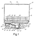
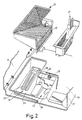
- FIG. 1 shows a vertical sectiont through a dishwasher according to invention whereas Fig. 2 in a exploded view shows the lower part of the tub and Fig. 3 is a vertical section through a suction part forming a tube-shaped connection of the dishwasher.
- the dishwasher comprises a tub having side walls 11 a rear wall 12, a roof part 13 and a bottom 14. Moreover there is a door, not shown, which normally covers the front wall.
- One or several baskets 15 with dish can be inserted into the tub.
- the bottom of the dishwasher is inclined downwards to a collecting container 16 which is shaped as pan a part of the container forming a sump 17 in which the inlet 18 to a drain pump 19 is placed.
- the container 16 is covered by a fine sieve 20 and a coarse sieve 21 which both can be lifted from the container for cleaning.
- the fine sieve 20 covers the upper part of the container and also forms a partition wall 22 in the container so that a chamber 23 is created.
- This chamber communicates, via an inlet opening 25 adjacent the bottom of the chamber and a tube shaped connection 26, with the suction side of a circulation pump 27 having an outlet connected to a pipe 28 which is centrally placed in the dishwasher and on which a spray arm 29 with nozzles 30 is placed for rotating motion.
- the chamber 23 also encloses a heating source 31 in the form of an electric coil or the like extending horisontaly from one of the walls of the chamber.
- connection 26 the lower part of which is provided with the downwardly extending comparatively large inlet opening 25 and the upper end of which communicates with the circulation pump, has a slot-shaped, curved opening 32 facing towards the chamber and being placed somewhat above the upper heat emitting part of the heating source 31 which means that the surface of the opening 32 exposed to the chamber above the liquid level increases when the liquid level sinks.
- the arrangement operates in the following way.
- the liquid flowing out from the nozzles 30 is collected at the bottom of the tub and is directed towards the container 16 and flows through and on the fine sieve 20 and the coarse sieve 21 into the chamber 23 from which the liquid is sucked out by means of the circulation pump 27 and is delivered to the rotating disharm 29.
- the liquid level in the chamber 23 is normally situated above the heating source. Should however the fine sieve 20 become so clogged that the liquid level in the chamber 23 sinks because the capacity of the circulation pump 27 exceeds the incoming flow the opening 32 will successively be uncovered which means that the circulation pump will suck more and more air and gradually reduce the flow of water to the pump resulting in a balanced water level.
Landscapes
- Washing And Drying Of Tableware (AREA)
Claims (3)
- Anordnung für eine Geschirrspülmaschine, die eine Wanne (10) umfaßt, in der das Geschirr angeordnet ist und in der mittels einer Umwälzpumpe (27), die über eine rohrförmige Verbindung (26) mit einem Einlaß (25) verbunden ist, der im unteren Bereich einer am Boden der Wanne vorgesehenen Kammer (23) angeordnet ist, Flüssigkeit umgewälzt wird, wobei die Kammer durch einen Filter (20) oder dergleichen zumindest teilweise von der Wanne getrennt ist, wobei die Kammer weiterhin eine Heizquelle (31) zum Erwärmen der Flüssigkeit aufweist, wobei die Verbindung (26) zusätzlich zu dem Einlaß (25) eine Öffnung (32) aufweist, die zumindest teilweise oberhalb oder auf gleicher Höhe der wärmeaussendenden Teile der Heizquelle angeordnet ist, dadurch gekennzeichnet, daß zwischen einem bestimmten Pegelintervall der Teil der Öffnung (32), der nicht von der Flüssigkeit verdeckt ist, allmählich zunimmt, wenn der Flüssigkeitspegel in der Kammer sinkt.
- Anordnung nach Anspruch 1, dadurch gekennzeichnet, daß sich die Verbindung (26) vom unteren Bereich der Kammer aus nach oben zur Pumpe erstreckt.
- Anordnung nach einem der vorhergehenden Ansprüche, da durch gekennzeichnet, daß die Öffnung (32) schlitzförmig ist.
Priority Applications (1)
| Application Number | Priority Date | Filing Date | Title |
|---|---|---|---|
| AT9090850376T ATE104530T1 (de) | 1989-12-22 | 1990-11-16 | Wasserstandsregelvorrichtung fuer geschirrspuelmaschinen. |
Applications Claiming Priority (2)
| Application Number | Priority Date | Filing Date | Title |
|---|---|---|---|
| SE8904351 | 1989-12-22 | ||
| SE8904351A SE469056B (sv) | 1989-12-22 | 1989-12-22 | Nivaaregleringsanordning vid en diskmaskin |
Publications (2)
| Publication Number | Publication Date |
|---|---|
| EP0437189A1 EP0437189A1 (de) | 1991-07-17 |
| EP0437189B1 true EP0437189B1 (de) | 1994-04-20 |
Family
ID=20377861
Family Applications (1)
| Application Number | Title | Priority Date | Filing Date |
|---|---|---|---|
| EP90850376A Expired - Lifetime EP0437189B1 (de) | 1989-12-22 | 1990-11-16 | Wasserstandsregelvorrichtung für Geschirrspülmaschinen |
Country Status (6)
| Country | Link |
|---|---|
| US (1) | US5129411A (de) |
| EP (1) | EP0437189B1 (de) |
| JP (1) | JPH03195531A (de) |
| AT (1) | ATE104530T1 (de) |
| DE (1) | DE69008330T2 (de) |
| SE (1) | SE469056B (de) |
Families Citing this family (32)
| Publication number | Priority date | Publication date | Assignee | Title |
|---|---|---|---|---|
| USD370096S (en) | 1994-10-14 | 1996-05-21 | Cuda Corporation | Parts washer |
| IT1282922B1 (it) * | 1995-01-09 | 1998-04-01 | Zanussi Elettrodomestici | Lavastoviglie con mezzi elettrici di riscaldamento |
| US5499640A (en) * | 1995-02-24 | 1996-03-19 | White Consolidated Industries, Inc. | Dishwasher with venturi drain |
| USD374316S (en) | 1995-05-01 | 1996-10-01 | Cuda Corporation | Parts washer |
| US5640981A (en) * | 1995-05-01 | 1997-06-24 | Cuda Corporation | Parts washer |
| US5937880A (en) * | 1997-10-03 | 1999-08-17 | Tca, Inc. | Under counter dish washing machine |
| US6257254B1 (en) * | 1997-11-14 | 2001-07-10 | Steris Corporation | Cleaning system for a washer |
| US6887318B2 (en) * | 2003-07-09 | 2005-05-03 | Whirlpool Corporation | Adaptive fill for dishwashers |
| KR20090024591A (ko) * | 2007-09-04 | 2009-03-09 | 엘지전자 주식회사 | 식기 세척기의 오물 채집 장치 |
| US8667974B2 (en) | 2009-12-21 | 2014-03-11 | Whirlpool Corporation | Rotating filter for a dishwashing machine |
| US8627832B2 (en) | 2010-12-13 | 2014-01-14 | Whirlpool Corporation | Rotating filter for a dishwashing machine |
| US9119515B2 (en) | 2010-12-03 | 2015-09-01 | Whirlpool Corporation | Dishwasher with unitary wash module |
| US9687135B2 (en) | 2009-12-21 | 2017-06-27 | Whirlpool Corporation | Automatic dishwasher with pump assembly |
| US9918609B2 (en) | 2009-12-21 | 2018-03-20 | Whirlpool Corporation | Rotating drum filter for a dishwashing machine |
| US9668636B2 (en) | 2010-11-16 | 2017-06-06 | Whirlpool Corporation | Method and apparatus for dishwasher with common heating element for multiple treating chambers |
| US9113766B2 (en) | 2010-11-16 | 2015-08-25 | Whirlpool Corporation | Method and apparatus for dishwasher with common heating element for multiple treating chambers |
| US9034112B2 (en) | 2010-12-03 | 2015-05-19 | Whirlpool Corporation | Dishwasher with shared heater |
| US8733376B2 (en) | 2011-05-16 | 2014-05-27 | Whirlpool Corporation | Dishwasher with filter assembly |
| US9107559B2 (en) | 2011-05-16 | 2015-08-18 | Whirlpool Corporation | Dishwasher with filter assembly |
| US9265401B2 (en) | 2011-06-20 | 2016-02-23 | Whirlpool Corporation | Rotating filter for a dishwashing machine |
| US9861251B2 (en) | 2011-06-20 | 2018-01-09 | Whirlpool Corporation | Filter with artificial boundary for a dishwashing machine |
| US9005369B2 (en) | 2011-06-20 | 2015-04-14 | Whirlpool Corporation | Filter assembly for a dishwasher |
| US9010344B2 (en) | 2011-06-20 | 2015-04-21 | Whirlpool Corporation | Rotating filter for a dishwashing machine |
| US20120318296A1 (en) | 2011-06-20 | 2012-12-20 | Whirlpool Corporation | Ultra micron filter for a dishwasher |
| US9301667B2 (en) | 2012-02-27 | 2016-04-05 | Whirlpool Corporation | Soil chopping system for a dishwasher |
| US9730570B2 (en) | 2012-05-30 | 2017-08-15 | Whirlpool Corporation | Reduced sound with a rotating filter for a dishwasher |
| US9237836B2 (en) | 2012-05-30 | 2016-01-19 | Whirlpool Corporation | Rotating filter for a dishwasher |
| US9451862B2 (en) | 2012-06-01 | 2016-09-27 | Whirlpool Corporation | Dishwasher with unitary wash module |
| US9532700B2 (en) | 2012-06-01 | 2017-01-03 | Whirlpool Corporation | Dishwasher with overflow conduit |
| US9833120B2 (en) | 2012-06-01 | 2017-12-05 | Whirlpool Corporation | Heating air for drying dishes in a dishwasher using an in-line wash liquid heater |
| US9554688B2 (en) | 2012-10-23 | 2017-01-31 | Whirlpool Corporation | Rotating filter for a dishwasher and methods of cleaning a rotating filter |
| CN108284100A (zh) * | 2018-04-04 | 2018-07-17 | 新乡市振英机械设备有限公司 | 一种利于环保的垃圾输送用除尘装置 |
Family Cites Families (10)
| Publication number | Priority date | Publication date | Assignee | Title |
|---|---|---|---|---|
| US1661356A (en) * | 1926-09-15 | 1928-03-06 | Wedworth V Baker | Washing machine |
| US2083012A (en) * | 1934-02-15 | 1937-06-08 | Ici Ltd | Degreasing apparatus |
| US2674249A (en) * | 1951-05-21 | 1954-04-06 | Gen Electric | Air flow controller for dishwashing and drying machines |
| US3103227A (en) * | 1961-04-18 | 1963-09-10 | Westinghouse Electric Corp | Dishwasher apparatus |
| US3702680A (en) * | 1971-11-08 | 1972-11-14 | Fedders Corp | Gentle wash mechanism for a dishwasher |
| DE2408573A1 (de) * | 1974-02-22 | 1975-09-04 | Euro Hausgeraete Gmbh | Geschirrspuelmaschine |
| DE2412257A1 (de) * | 1974-03-14 | 1975-09-25 | Euro Hausgeraete Gmbh | Geschirrspuelmaschine |
| US4277290A (en) * | 1980-01-25 | 1981-07-07 | American Sterilizer Company | Low temperature washing and chemical sanitizing of foodware |
| DE3167847D1 (en) * | 1980-09-24 | 1985-01-31 | Unilever Nv | Mechanical dishwashing process and apparatus |
| IT1192076B (it) * | 1986-04-09 | 1988-03-31 | Zanussi Elettrodomestici | Filtro per macchine lavabiancheria |
-
1989
- 1989-12-22 SE SE8904351A patent/SE469056B/sv not_active IP Right Cessation
-
1990
- 1990-11-16 EP EP90850376A patent/EP0437189B1/de not_active Expired - Lifetime
- 1990-11-16 AT AT9090850376T patent/ATE104530T1/de not_active IP Right Cessation
- 1990-11-16 DE DE69008330T patent/DE69008330T2/de not_active Expired - Fee Related
- 1990-11-28 JP JP2323398A patent/JPH03195531A/ja active Pending
- 1990-12-13 US US07/626,968 patent/US5129411A/en not_active Expired - Fee Related
Also Published As
| Publication number | Publication date |
|---|---|
| ATE104530T1 (de) | 1994-05-15 |
| SE8904351D0 (sv) | 1989-12-22 |
| US5129411A (en) | 1992-07-14 |
| SE8904351L (sv) | 1991-06-23 |
| SE469056B (sv) | 1993-05-10 |
| JPH03195531A (ja) | 1991-08-27 |
| EP0437189A1 (de) | 1991-07-17 |
| DE69008330D1 (de) | 1994-05-26 |
| DE69008330T2 (de) | 1994-09-29 |
Similar Documents
| Publication | Publication Date | Title |
|---|---|---|
| US5129411A (en) | Liquid level control arrangement for a dishwasher | |
| US7232494B2 (en) | Stop start wash cycle for dishwashers | |
| US4673441A (en) | Dishwashing method | |
| US4998548A (en) | Self-cleaning filter for a dishwasher | |
| US4559959A (en) | Dishwashing apparatus | |
| EP0240911B1 (de) | Filter für eine Waschmaschine | |
| EP0082592A1 (de) | Geschirrspüler | |
| EP0649623B1 (de) | Kocher für Teigwaren | |
| EP0365500B1 (de) | Geschirrspülmaschine | |
| US5900070A (en) | Automatic thermal input system for a dishwasher | |
| US5184635A (en) | Fluid handling system for a dishwasher | |
| US5127417A (en) | Soil separator for a dishwasher | |
| CA1268397A (en) | Arrangement in a dish-washing machine for reducing clogging | |
| US5016667A (en) | Device for a dish-washer | |
| EP0493065B1 (de) | Luftströmungskontrolle für einen Geschirrspüler | |
| EP0188858B2 (de) | Maschine zum Spülen von Geschirr | |
| US5168885A (en) | Power system for a dishwasher | |
| JPH02302626A (ja) | 水準感知装置 | |
| EP0378058A1 (de) | Vorrichtung für Geschirrspülmaschinen | |
| CN101778589B (zh) | 洗碗机 | |
| WO1999060914A1 (en) | Method and device in a cleaning machine | |
| KR100267921B1 (ko) | 식기세척기 | |
| SE464387B (sv) | Med granuler arbetande rengoeringsmaskin | |
| GB2192532A (en) | Glass or dish washing machine | |
| JPS61191332A (ja) | 皿洗い装置及び方法 |
Legal Events
| Date | Code | Title | Description |
|---|---|---|---|
| PUAI | Public reference made under article 153(3) epc to a published international application that has entered the european phase |
Free format text: ORIGINAL CODE: 0009012 |
|
| AK | Designated contracting states |
Kind code of ref document: A1 Designated state(s): AT DE FR GR IT SE |
|
| 17P | Request for examination filed |
Effective date: 19911213 |
|
| 17Q | First examination report despatched |
Effective date: 19930517 |
|
| GRAA | (expected) grant |
Free format text: ORIGINAL CODE: 0009210 |
|
| AK | Designated contracting states |
Kind code of ref document: B1 Designated state(s): AT DE FR GR IT SE |
|
| PG25 | Lapsed in a contracting state [announced via postgrant information from national office to epo] |
Ref country code: SE Free format text: THE PATENT HAS BEEN ANNULLED BY A DECISION OF A NATIONAL AUTHORITY Effective date: 19940420 |
|
| REF | Corresponds to: |
Ref document number: 104530 Country of ref document: AT Date of ref document: 19940515 Kind code of ref document: T |
|
| REF | Corresponds to: |
Ref document number: 69008330 Country of ref document: DE Date of ref document: 19940526 |
|
| ITF | It: translation for a ep patent filed | ||
| REG | Reference to a national code |
Ref country code: GR Ref legal event code: FG4A Free format text: 3011949 |
|
| ET | Fr: translation filed | ||
| PLBE | No opposition filed within time limit |
Free format text: ORIGINAL CODE: 0009261 |
|
| STAA | Information on the status of an ep patent application or granted ep patent |
Free format text: STATUS: NO OPPOSITION FILED WITHIN TIME LIMIT |
|
| 26N | No opposition filed | ||
| PGFP | Annual fee paid to national office [announced via postgrant information from national office to epo] |
Ref country code: FR Payment date: 19961111 Year of fee payment: 7 |
|
| PGFP | Annual fee paid to national office [announced via postgrant information from national office to epo] |
Ref country code: AT Payment date: 19961114 Year of fee payment: 7 |
|
| PG25 | Lapsed in a contracting state [announced via postgrant information from national office to epo] |
Ref country code: AT Free format text: LAPSE BECAUSE OF NON-PAYMENT OF DUE FEES Effective date: 19971116 |
|
| PG25 | Lapsed in a contracting state [announced via postgrant information from national office to epo] |
Ref country code: FR Free format text: THE PATENT HAS BEEN ANNULLED BY A DECISION OF A NATIONAL AUTHORITY Effective date: 19971130 |
|
| REG | Reference to a national code |
Ref country code: FR Ref legal event code: ST |
|
| PGFP | Annual fee paid to national office [announced via postgrant information from national office to epo] |
Ref country code: DE Payment date: 20021121 Year of fee payment: 13 |
|
| PGFP | Annual fee paid to national office [announced via postgrant information from national office to epo] |
Ref country code: GR Payment date: 20021128 Year of fee payment: 13 |
|
| PG25 | Lapsed in a contracting state [announced via postgrant information from national office to epo] |
Ref country code: DE Free format text: LAPSE BECAUSE OF NON-PAYMENT OF DUE FEES Effective date: 20040602 |
|
| PG25 | Lapsed in a contracting state [announced via postgrant information from national office to epo] |
Ref country code: GR Free format text: LAPSE BECAUSE OF NON-PAYMENT OF DUE FEES Effective date: 20040603 |
|
| PG25 | Lapsed in a contracting state [announced via postgrant information from national office to epo] |
Ref country code: IT Free format text: LAPSE BECAUSE OF NON-PAYMENT OF DUE FEES;WARNING: LAPSES OF ITALIAN PATENTS WITH EFFECTIVE DATE BEFORE 2007 MAY HAVE OCCURRED AT ANY TIME BEFORE 2007. THE CORRECT EFFECTIVE DATE MAY BE DIFFERENT FROM THE ONE RECORDED. Effective date: 20051116 |