EP0437214A2 - Méthode de diagnose de détérioration d'isolation d'un appareil électrique - Google Patents
Méthode de diagnose de détérioration d'isolation d'un appareil électrique Download PDFInfo
- Publication number
- EP0437214A2 EP0437214A2 EP91100103A EP91100103A EP0437214A2 EP 0437214 A2 EP0437214 A2 EP 0437214A2 EP 91100103 A EP91100103 A EP 91100103A EP 91100103 A EP91100103 A EP 91100103A EP 0437214 A2 EP0437214 A2 EP 0437214A2
- Authority
- EP
- European Patent Office
- Prior art keywords
- direct current
- insulation
- current component
- voltage
- cable
- Prior art date
- Legal status (The legal status is an assumption and is not a legal conclusion. Google has not performed a legal analysis and makes no representation as to the accuracy of the status listed.)
- Granted
Links
Images


Classifications
-
- G—PHYSICS
- G01—MEASURING; TESTING
- G01R—MEASURING ELECTRIC VARIABLES; MEASURING MAGNETIC VARIABLES
- G01R31/00—Arrangements for testing electric properties; Arrangements for locating electric faults; Arrangements for electrical testing characterised by what is being tested not provided for elsewhere
- G01R31/12—Testing dielectric strength or breakdown voltage ; Testing or monitoring effectiveness or level of insulation, e.g. of a cable or of an apparatus, for example using partial discharge measurements; Electrostatic testing
- G01R31/1227—Testing dielectric strength or breakdown voltage ; Testing or monitoring effectiveness or level of insulation, e.g. of a cable or of an apparatus, for example using partial discharge measurements; Electrostatic testing of components, parts or materials
- G01R31/1263—Testing dielectric strength or breakdown voltage ; Testing or monitoring effectiveness or level of insulation, e.g. of a cable or of an apparatus, for example using partial discharge measurements; Electrostatic testing of components, parts or materials of solid or fluid materials, e.g. insulation films, bulk material; of semiconductors or LV electronic components or parts; of cable, line or wire insulation
- G01R31/1272—Testing dielectric strength or breakdown voltage ; Testing or monitoring effectiveness or level of insulation, e.g. of a cable or of an apparatus, for example using partial discharge measurements; Electrostatic testing of components, parts or materials of solid or fluid materials, e.g. insulation films, bulk material; of semiconductors or LV electronic components or parts; of cable, line or wire insulation of cable, line or wire insulation, e.g. using partial discharge measurements
-
- G—PHYSICS
- G01—MEASURING; TESTING
- G01R—MEASURING ELECTRIC VARIABLES; MEASURING MAGNETIC VARIABLES
- G01R31/00—Arrangements for testing electric properties; Arrangements for locating electric faults; Arrangements for electrical testing characterised by what is being tested not provided for elsewhere
- G01R31/50—Testing of electric apparatus, lines, cables or components for short-circuits, continuity, leakage current or incorrect line connections
- G01R31/52—Testing for short-circuits, leakage current or ground faults
-
- G—PHYSICS
- G01—MEASURING; TESTING
- G01R—MEASURING ELECTRIC VARIABLES; MEASURING MAGNETIC VARIABLES
- G01R31/00—Arrangements for testing electric properties; Arrangements for locating electric faults; Arrangements for electrical testing characterised by what is being tested not provided for elsewhere
- G01R31/50—Testing of electric apparatus, lines, cables or components for short-circuits, continuity, leakage current or incorrect line connections
- G01R31/58—Testing of lines, cables or conductors
Definitions
- the invention relates to a method for diagnosing an insulation deterioration of an electric apparatus, and more particularly to a method for diagnosing an insulation deterioration of a power cable such as a cross-linked polyethylene insulated cable, in which an insulation deterioration of the cable is detected under a state that a rated line voltage is applied to a power cable system.
- CV cable cross-linked polyethylene insulated cable
- a first type of a conventional method for diagnosing an insulation deterioration of a power cable comprises a step of measuring an insulation resistance of the power cable by use of a megger.
- a second type of a conventional method for diagnosing an insulation deterioration of a power cable comprises steps of applying a direct current (DC) high voltage to an insulation of the power cable, and detecting leakage direct current flowing through the insulation, so that the insulation deterioration is diagnosed dependent on a level of the leakage direct current.
- DC direct current
- Another method of diagnosing an insulation deterioration of a power cable has been proposed to detect water trees generated in a deteriorated insulation of a 6 kV power distribution CV cable.
- This method comprises steps of detecting a direct current component of a minute level included in a charging current of the CV cable in a state that a 6 kV power distribution voltage is applied to the CV cable to supply electric power to loads of a power distribution system, and diagnosing whether an insulation deterioration has occured in the insulation by checking value and waveform of the direct current component.
- the detection of the direct current component is carried out by use of a ground wire of the CV cable, through which the direct current component flows.
- this proposed method is not applied to a CV cable power distribution system having a line voltage of more than 22 KV, because the CV cable is connected to ground at multi-points. Even if the CV cable is not connected to ground at the multi-points, the detection of the direct current component is very hard at an installation site of the CV cable, because much noise is detected to lower a S/N ratio.
- a method for diagnosing an insulation deterioration of an electric apparatus comprises steps of: applying an AC voltage across two conducting members insulated by an insulation to detect a direct current component flowing through the insulation; amplifying the direct current component by biasing a DC voltage to the AC voltage to provide an amplified direct current component; and determining the insulation deterioration by an absolute value of the amplified direct current component.
- a polarity and a level of the DC voltage to be biased to the AC voltage is determined by a polarity and a level of the direct current component flowing through the insulation only by applying the AC voltage. Consequently, no breakdown of the insulation occurs during the diagnosis procedure of the insulation deterioration.
- This invention is advantageously applied to the diagnosis of an insulation deterioration for a CV cable of more than 22 KV.
- an AC voltage is applied across a conductor and a metal shield which is connected to ground to detect a direct current component flowing through a cross-linked polyethylene insulation.
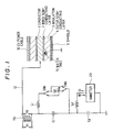
- FIG. 1 shows a method for diagnosing an insulation deterioration of a CV cable 10 having a water tree 15 in a cross-linked polyethylene insulation 3 in the preferred embodiment according to the invention.
- a circuit for detecting a direct current component flowing through the insulation 3 comprises a transformer TR for applying an AC voltage V2 which is obtained from an AC voltage V1 through a lead 12 to a conductor 1 of the CV cable 10, capacitances C1 and C2 provided between a secondary winding of the transformer TR and ground, a DC voltage biasing circuit including a blocking coil L1, a DC power supply Vdc, and switches SW1 and SW2 for changing a polarity of a bias DC voltage, and a direct current component detecting circuit including a blocking coil L2 and an ammeter 20.
- the CV cable 10 comprises a conductor 1, an inner semiconductive layer 2 provided on the conductor 1, the cross-linked polyethylene insulation 3, an outer semiconducting layer 4 provided on the insulation 3, and a metal shield 5 connected to ground.
- a polyvinyl-chloride anti-corrosion layer provided on the metal shield 5 is not shown in Fig. 1.
- a polarity of a direct current component is positive, when the direct current component flows from the metal shield 5 to the conductor 1.
- the polarity is shown in Fig. 1 by the symbols ⁇ and ⁇ .
- an AC voltage obtained at secondary terminals of the transformer TR is applied across the conductor 1 and the metal shield 5, so that a charging current flows through the insulation 3.
- a direct current component which is included in the charging current is detected by the ammeter 20.
- the switches SW1 and SW2 are turned on, as shown by dotted lines.
- the positive direct current is amplified, and is detected by the ammeter 20.
- the switches SW1, and SW2 are turned on, as shown by solid lines.
- the negative direct current component is amplified, and is detected by the ammeter 20.
- Fig. 2A shows an amplified direct current component Idc, when a negative bias voltage -Vdc is applied to the conductor 1, that is, the switchs SW1 and SW2 are turned on by the dotted lines.
- the direct current component Idc increases with a relatively complicated motion, as the negative bias voltage -Vdc increases in its absolute value.
- the direct current component Idc is amplified by two to three figures, as compared to a direct current component flowing through the insulation 3 only by the application of an AC voltage.
- Fig. 2B shows an amplified direct current component -Idc, when a positive bias voltage Vdc is applied to the conductor 1, that is, the switches SW1 and SW2 are turned on by the solid lines.
- the positive direct current component ⁇ decreases, as the positive bias voltage Vdc increases from zero to approximately 101 V, and the positive direct current component ⁇ becomes zero at a positive bias voltage +Vdc.
- a negative direct current component -Idc begins to flow through the insulation 3, as the positive bias voltage Vdc further increases, and the negative direct current component -Idc increases in its absolute value in proportional to the increase of the positive bias voltage Vdc.
- Fig. 3 shows a method for diagnosing an insulation deterioration of a CV cable 10 which is connected at multi-points to ground.
- a conductor of the CV cable 10 is connected through a lead 12 to a transformer TR by a terminal joint 11.
- the transformer TR is connected through serial capacitances C1 and C2 to ground, and a DC bias voltage applying circuit including a blocking coil L1 and a DC power supply Vdc and a direct current component detecting circuit including a choke coil L2 and an ammeter 20 are connected in parallel to the capacitances C1 and C2, respectively.
- the detection of a direct current component and an amplified direct current component is carried out on the CV cable 10 which has been installed at an installation site in the same manner as the operation in Fig. 1. Then, the CV cable is removed from the installation site, and is subject to an AC voltage breakdown test. The length of water trees found in an insulation of the removed CV cable is measured. The results are shown in TABLE 1.
- a CV cable having an insulation deteriorated by water tree can be precisely detected by measuring a direct current component flowing at the time of an AC voltage application and an amplified direct current component flowing at the time of an AC voltage and DC bias voltage applications.
- This invention is not applied to a CV cable, but other cables such as an oil filled (OF) cable, a rubber insulated cable, etc., a normal joint, a terminal joint, etc. of power cable, and electric machines such as a transformer, an electric motor, an arrester, etc.
- OF oil filled
- a rubber insulated cable etc.
- a normal joint a terminal joint, etc. of power cable
- electric machines such as a transformer, an electric motor, an arrester, etc.
Landscapes
- Physics & Mathematics (AREA)
- General Physics & Mathematics (AREA)
- Testing Relating To Insulation (AREA)
- Testing Of Short-Circuits, Discontinuities, Leakage, Or Incorrect Line Connections (AREA)
Applications Claiming Priority (2)
| Application Number | Priority Date | Filing Date | Title |
|---|---|---|---|
| JP2002186A JPH0619416B2 (ja) | 1990-01-09 | 1990-01-09 | 絶縁診断法 |
| JP2186/90 | 1990-01-09 |
Publications (3)
| Publication Number | Publication Date |
|---|---|
| EP0437214A2 true EP0437214A2 (fr) | 1991-07-17 |
| EP0437214A3 EP0437214A3 (en) | 1992-05-06 |
| EP0437214B1 EP0437214B1 (fr) | 1995-06-07 |
Family
ID=11522334
Family Applications (1)
| Application Number | Title | Priority Date | Filing Date |
|---|---|---|---|
| EP91100103A Expired - Lifetime EP0437214B1 (fr) | 1990-01-09 | 1991-01-02 | Méthode de diagnose de détérioration d'isolation d'un appareil électrique |
Country Status (3)
| Country | Link |
|---|---|
| EP (1) | EP0437214B1 (fr) |
| JP (1) | JPH0619416B2 (fr) |
| DE (1) | DE69110138T2 (fr) |
Cited By (8)
| Publication number | Priority date | Publication date | Assignee | Title |
|---|---|---|---|---|
| EP0768810A1 (fr) * | 1995-10-09 | 1997-04-16 | Adb-Alnaco, Inc. | Système de détection et de mesure de défaut d'isolement sur un dispositif d'éclairage d'aéroport |
| EP0737318A4 (fr) * | 1993-12-30 | 1997-04-23 | Univ Connecticut | Systeme a courant alternatif a polarisation continue pour l'essai de cables haute tension |
| US5638057A (en) * | 1994-05-09 | 1997-06-10 | Adb-Alnaco, Inc. | Ground fault detection and measurement system for airfield lighting system |
| US5648723A (en) * | 1994-05-09 | 1997-07-15 | Adb-Alnaco, Inc. | Method and apparatus for separating and analyzing composite AC/DC waveforms |
| WO1999026076A1 (fr) * | 1997-11-18 | 1999-05-27 | Emerson Electric Co. | Systeme et procede de surveillance de l'etat de l'isolation recouvrant le fil d'un enroulement |
| US5969642A (en) * | 1993-05-06 | 1999-10-19 | Siemens Energy & Automation, Inc. | Airfield lighting system |
| EP0990916A4 (fr) * | 1998-04-14 | 2002-01-30 | Furukawa Electric Co Ltd | Procede pour diagnostiquer la deterioration d'un cable electrique |
| CN109580463A (zh) * | 2018-11-22 | 2019-04-05 | 国网天津市电力公司电力科学研究院 | 一种测量接地网腐蚀程度的方法 |
Families Citing this family (3)
| Publication number | Priority date | Publication date | Assignee | Title |
|---|---|---|---|---|
| KR101180830B1 (ko) * | 2008-10-13 | 2012-09-07 | 주식회사 엘지화학 | 셀 모듈 어셈블리의 절연성 검사 장치와 방법 및 이를 위한 프로브 |
| KR101142459B1 (ko) * | 2008-10-14 | 2012-05-08 | 에스케이이노베이션 주식회사 | 절연파괴 측정회로 |
| JP2019138864A (ja) * | 2018-02-15 | 2019-08-22 | 東京電力ホールディングス株式会社 | Ofケーブルの劣化診断方法 |
-
1990
- 1990-01-09 JP JP2002186A patent/JPH0619416B2/ja not_active Expired - Fee Related
-
1991
- 1991-01-02 DE DE69110138T patent/DE69110138T2/de not_active Expired - Fee Related
- 1991-01-02 EP EP91100103A patent/EP0437214B1/fr not_active Expired - Lifetime
Cited By (11)
| Publication number | Priority date | Publication date | Assignee | Title |
|---|---|---|---|---|
| US5969642A (en) * | 1993-05-06 | 1999-10-19 | Siemens Energy & Automation, Inc. | Airfield lighting system |
| EP0737318A4 (fr) * | 1993-12-30 | 1997-04-23 | Univ Connecticut | Systeme a courant alternatif a polarisation continue pour l'essai de cables haute tension |
| US5638057A (en) * | 1994-05-09 | 1997-06-10 | Adb-Alnaco, Inc. | Ground fault detection and measurement system for airfield lighting system |
| US5648723A (en) * | 1994-05-09 | 1997-07-15 | Adb-Alnaco, Inc. | Method and apparatus for separating and analyzing composite AC/DC waveforms |
| US5872457A (en) * | 1994-05-09 | 1999-02-16 | Adb-Alnaco, Inc. | Method and apparatus for separating and analyzing composite AC/DC waveforms |
| EP0768810A1 (fr) * | 1995-10-09 | 1997-04-16 | Adb-Alnaco, Inc. | Système de détection et de mesure de défaut d'isolement sur un dispositif d'éclairage d'aéroport |
| WO1999026076A1 (fr) * | 1997-11-18 | 1999-05-27 | Emerson Electric Co. | Systeme et procede de surveillance de l'etat de l'isolation recouvrant le fil d'un enroulement |
| US6087836A (en) * | 1997-11-18 | 2000-07-11 | Emerson Electric Co. | Apparatus for and method of monitoring the status of the insulation on the wire in a winding |
| US6392419B1 (en) | 1997-11-18 | 2002-05-21 | Emerson Electric Co. | Apparatus for and method of monitoring the status of the insulation on the wire in a winding |
| EP0990916A4 (fr) * | 1998-04-14 | 2002-01-30 | Furukawa Electric Co Ltd | Procede pour diagnostiquer la deterioration d'un cable electrique |
| CN109580463A (zh) * | 2018-11-22 | 2019-04-05 | 国网天津市电力公司电力科学研究院 | 一种测量接地网腐蚀程度的方法 |
Also Published As
| Publication number | Publication date |
|---|---|
| EP0437214A3 (en) | 1992-05-06 |
| JPH0619416B2 (ja) | 1994-03-16 |
| DE69110138T2 (de) | 1995-10-19 |
| EP0437214B1 (fr) | 1995-06-07 |
| DE69110138D1 (de) | 1995-07-13 |
| JPH03206976A (ja) | 1991-09-10 |
Similar Documents
| Publication | Publication Date | Title |
|---|---|---|
| US5276401A (en) | Method for diagnosing an insulation deterioration of an electric apparatus | |
| US4356443A (en) | Detection of arcing faults in polyphase electric machines | |
| Eager et al. | High voltage VLF testing of power cables | |
| US4980645A (en) | Method for diagnosing an insulation deterioration of a power cable | |
| EP0437214A2 (fr) | Méthode de diagnose de détérioration d'isolation d'un appareil électrique | |
| EP4226168B1 (fr) | Système et procédé de détection de connexion défectueuse dans une grille de mise à la terre | |
| CN1042683C (zh) | 对地泄漏单元 | |
| JP2011242206A (ja) | 電力ケーブルの絶縁劣化診断方法及び絶縁劣化診断装置 | |
| JP3308197B2 (ja) | ケーブルの劣化診断方法 | |
| JP2876322B2 (ja) | Cvケーブルの絶縁劣化診断方法 | |
| JPS6331747B2 (fr) | ||
| KR100521635B1 (ko) | 주접지극 탐색장치 | |
| JPH10160778A (ja) | 活線電力ケーブルの絶縁劣化診断方法、及びこれを用いた絶縁劣化診断装置 | |
| JPH07306241A (ja) | 電力ケーブルの絶縁劣化判定法 | |
| JPH062518U (ja) | トリー検出体を有する電力ケーブル | |
| JP2007271542A (ja) | 電力ケーブルの絶縁劣化診断方法及び絶縁劣化診断装置 | |
| JPH09304467A (ja) | 電気絶縁物の絶縁劣化診断方法 | |
| JP2612648B2 (ja) | 三相電力ケーブルの絶縁劣化判定方法 | |
| JPH07235244A (ja) | 開閉器の絶縁劣化検出方法 | |
| JP2017026491A (ja) | Ofケーブルの劣化診断方法 | |
| JPS63281073A (ja) | Cvケ−ブルの水トリ−電流検出方法 | |
| JP3007169U (ja) | 漏電圧検出器 | |
| JP2001305174A (ja) | 高電圧絶縁機器の直流漏れ電流測定法 | |
| JPH10325850A (ja) | 絶縁劣化診断装置 | |
| JPH0546906B2 (fr) |
Legal Events
| Date | Code | Title | Description |
|---|---|---|---|
| PUAI | Public reference made under article 153(3) epc to a published international application that has entered the european phase |
Free format text: ORIGINAL CODE: 0009012 |
|
| 17P | Request for examination filed |
Effective date: 19910102 |
|
| AK | Designated contracting states |
Kind code of ref document: A2 Designated state(s): DE FR GB SE |
|
| PUAL | Search report despatched |
Free format text: ORIGINAL CODE: 0009013 |
|
| AK | Designated contracting states |
Kind code of ref document: A3 Designated state(s): DE FR GB SE |
|
| 17Q | First examination report despatched |
Effective date: 19931122 |
|
| GRAA | (expected) grant |
Free format text: ORIGINAL CODE: 0009210 |
|
| AK | Designated contracting states |
Kind code of ref document: B1 Designated state(s): DE FR GB SE |
|
| REF | Corresponds to: |
Ref document number: 69110138 Country of ref document: DE Date of ref document: 19950713 |
|
| ET | Fr: translation filed | ||
| PLBE | No opposition filed within time limit |
Free format text: ORIGINAL CODE: 0009261 |
|
| STAA | Information on the status of an ep patent application or granted ep patent |
Free format text: STATUS: NO OPPOSITION FILED WITHIN TIME LIMIT |
|
| 26N | No opposition filed | ||
| REG | Reference to a national code |
Ref country code: GB Ref legal event code: IF02 |
|
| PGFP | Annual fee paid to national office [announced via postgrant information from national office to epo] |
Ref country code: GB Payment date: 20020102 Year of fee payment: 12 |
|
| PGFP | Annual fee paid to national office [announced via postgrant information from national office to epo] |
Ref country code: SE Payment date: 20020107 Year of fee payment: 12 |
|
| PGFP | Annual fee paid to national office [announced via postgrant information from national office to epo] |
Ref country code: FR Payment date: 20020110 Year of fee payment: 12 |
|
| PGFP | Annual fee paid to national office [announced via postgrant information from national office to epo] |
Ref country code: DE Payment date: 20020212 Year of fee payment: 12 |
|
| PG25 | Lapsed in a contracting state [announced via postgrant information from national office to epo] |
Ref country code: GB Free format text: LAPSE BECAUSE OF NON-PAYMENT OF DUE FEES Effective date: 20030102 |
|
| PG25 | Lapsed in a contracting state [announced via postgrant information from national office to epo] |
Ref country code: SE Free format text: LAPSE BECAUSE OF NON-PAYMENT OF DUE FEES Effective date: 20030103 |
|
| PG25 | Lapsed in a contracting state [announced via postgrant information from national office to epo] |
Ref country code: DE Free format text: LAPSE BECAUSE OF NON-PAYMENT OF DUE FEES Effective date: 20030801 |
|
| GBPC | Gb: european patent ceased through non-payment of renewal fee |
Effective date: 20030102 |
|
| EUG | Se: european patent has lapsed | ||
| PG25 | Lapsed in a contracting state [announced via postgrant information from national office to epo] |
Ref country code: FR Free format text: LAPSE BECAUSE OF NON-PAYMENT OF DUE FEES Effective date: 20030930 |
|
| REG | Reference to a national code |
Ref country code: FR Ref legal event code: ST |