EP0437253B1 - Appareil de dilution réglable continûment pour mélanger des volumes déterminés de liquides - Google Patents
Appareil de dilution réglable continûment pour mélanger des volumes déterminés de liquides Download PDFInfo
- Publication number
- EP0437253B1 EP0437253B1 EP91100239A EP91100239A EP0437253B1 EP 0437253 B1 EP0437253 B1 EP 0437253B1 EP 91100239 A EP91100239 A EP 91100239A EP 91100239 A EP91100239 A EP 91100239A EP 0437253 B1 EP0437253 B1 EP 0437253B1
- Authority
- EP
- European Patent Office
- Prior art keywords
- knob
- diluting device
- recess
- adjustment element
- volume
- Prior art date
- Legal status (The legal status is an assumption and is not a legal conclusion. Google has not performed a legal analysis and makes no representation as to the accuracy of the status listed.)
- Expired - Lifetime
Links
- 238000007865 diluting Methods 0.000 title claims description 22
- 239000007788 liquid Substances 0.000 title claims description 18
- 239000003085 diluting agent Substances 0.000 claims description 6
- 238000000605 extraction Methods 0.000 claims 1
- 239000002991 molded plastic Substances 0.000 description 3
- 239000000463 material Substances 0.000 description 2
- 238000005452 bending Methods 0.000 description 1
- 238000011109 contamination Methods 0.000 description 1
- 210000004905 finger nail Anatomy 0.000 description 1
- 230000004048 modification Effects 0.000 description 1
- 238000012986 modification Methods 0.000 description 1
- 238000009877 rendering Methods 0.000 description 1
Images
Classifications
-
- G—PHYSICS
- G01—MEASURING; TESTING
- G01N—INVESTIGATING OR ANALYSING MATERIALS BY DETERMINING THEIR CHEMICAL OR PHYSICAL PROPERTIES
- G01N1/00—Sampling; Preparing specimens for investigation
- G01N1/28—Preparing specimens for investigation including physical details of (bio-)chemical methods covered elsewhere, e.g. G01N33/50, C12Q
- G01N1/38—Diluting, dispersing or mixing samples
-
- B—PERFORMING OPERATIONS; TRANSPORTING
- B01—PHYSICAL OR CHEMICAL PROCESSES OR APPARATUS IN GENERAL
- B01L—CHEMICAL OR PHYSICAL LABORATORY APPARATUS FOR GENERAL USE
- B01L3/00—Containers or dishes for laboratory use, e.g. laboratory glassware; Droppers
- B01L3/02—Burettes; Pipettes
- B01L3/021—Pipettes, i.e. with only one conduit for withdrawing and redistributing liquids
- B01L3/0217—Pipettes, i.e. with only one conduit for withdrawing and redistributing liquids of the plunger pump type
- B01L3/0224—Pipettes, i.e. with only one conduit for withdrawing and redistributing liquids of the plunger pump type having mechanical means to set stroke length, e.g. movable stops
-
- G—PHYSICS
- G01—MEASURING; TESTING
- G01N—INVESTIGATING OR ANALYSING MATERIALS BY DETERMINING THEIR CHEMICAL OR PHYSICAL PROPERTIES
- G01N1/00—Sampling; Preparing specimens for investigation
- G01N1/28—Preparing specimens for investigation including physical details of (bio-)chemical methods covered elsewhere, e.g. G01N33/50, C12Q
- G01N1/38—Diluting, dispersing or mixing samples
- G01N2001/382—Diluting, dispersing or mixing samples using pistons of different sections
Definitions
- the present invention relates to an ajustable diluting device for mixing a predetermined volume of a liquid sample with a predetermined volume of a liquid diluent and including the features as specified in the pre-characterizing clause of claim 1.
- Such a diluting device as disclosed in US Patent US-A-4,141,250 includes a plural piston liquid drawing assembly in combination with a digital volume indicator providing a digital readout for indicating the precise volume in milliliters of a sample of liquid to be drawn into the device and thereafter expelled after mixing with a predetermined volume of liquid diluent.
- Two coaxial shafts are provided along the central line of an alongate body for actuating the piston assembly and adjusting a stop, respectively.
- a volume adjustment mechanism for one of the liquid volumes is rotatably mounted in a recess of the body including opposed windows to expose this adjustment mechanism for manual adjustment operation.
- the invention as claimed is intended to solve the problem of improving a diluting device of the kind described by rendering the volume adjustment mechanism more accessible for volume adjustment operation without reducing the advantages of the device. At the same time the risk of a rubber glove to be caught in an attempt to orperate the volume adjustment mechanism is to be avoided.
- An extractable knob to operate a rotatable adjustment shaft is principally known from DE-A-2 250 621 yet this disclosure concerns the adjustment of a delicate, e.g. electronic, apparatus where the respective adjusting means are to be protected against damage or unintended operation.
- US Patent US-A-4,988,481 discloses an electrically operated pipet having a volume adjustment knob that can be moved into a locking home position to avoid accidential volume adjustment. Yet in this case no shaft means are required extending through the knob for operating a piston. Accordingly the aforementioned problem does not exist.
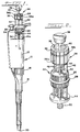
- the device 10 includes an elongated body 12 preferably formed of molded plastic material to include an axially aligned cylindrical recess 14 opening at the upper end of the body.
- a lower nose portion in the form of a tapered, tubular member 16 is attached to a lower end of the body 12 by means of a fluted nut 18.
- the diluting device 10 includes first and second chambers in the nose member 16 adapted to hold predetermined volumes of a liquid sample and a liquid diluent which are drawn up through an opening at the lower end 20 of the nose member 16 during a diluting operation.
- the diluting device 10 includes an internally positioned volume adjustment mechanism 22 mounted for rotation in the body recess 14 for movement along a central axis of the recess indicated by the axial line 24 in FIGS. 1, 3 and 4.
- the volume adjustment mechanism 22 includes a generally cylindrical knob-like adjustment element 26 formed of molded plastic and provided with an external groove at a mid-level for holding a resilient O-ring 28 adapted to frictionally engage an inside wall surface 14a of the recess 14 to normally retain the position of the adjustment element 26 after an adjustment has been made.
- the adjustment element 26 is secured to the upper end of an elongated, hollow, axially extending threaded element 30 which projects downwardly along the axis 24 into the lower end of the body 12 for adjusting the precise volume of a liquid sample that is drawn up into the diluting device 10 as more fully described in U.S. Patent US-A-4,141,250.
- the body 12 is provided with a pair of oblong windows 32 on opposite sides adjacent the upper end portion for exposing the adjustment element 26 so that manual rotation can be accomplished to provide a precise volume selection as required and as indicated in a digital readout mechanism 29, more fully described in U.S. Patent US-A-4,141,250.
- the adjustment element 26 When using the adjustment element 26 to adjust a volume of a liquid sample, sometimes a laboratory worker's glove tends to catch or become lodged in one of the windows 32 between an edge of the adjustment element 26 and the adjacent surface 14a or at the O-ring 28. Moreover, sometimes it is difficult to rotate the adjustment element 26 a desired amount because of the limited access through the windows 32. This is especially true for people not having good finger strength or good manual dexterity.
- the diluter device 10 includes a new and improved retractable, external rotating mechanism 34 which is accessible exteriorly of the body 12 for rapidly adjusting the desired volume of liquid to be sampled in the diluter device.
- the rotating mechanism 34 includes an upper, generally cylindrical, drive knob 36 preferably formed of molded plastic material and provided with a plurality of axially extending grooves or flutes 36a on the outer surface to facilitate turning of the knob manually or with a motor driven friction wheel.
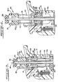
- the knob 36 also is provided with an annular groove 36b near the upper end to facilitate pulling the knob upwardly from the retracted position of FIG. 3 to an operational position as shown in FIG. 4 ready for manual rotation.
- the groove 36b permits a user to insert fingernails for easily pulling the knob upwardly.
- the knob 36 also includes a frustoconical-shaped recess 38 in the upper, outer end face thereof in coaxial alignment with the axis 24 in order to receive a push button 39 mounted on the upper end of a central shaft 40 of the plunger mechanism of the diluter device.
- the shaft 40 is displaced longitudinally when operated to withdraw and expel liquid samples into the respective volumes of the device 10.
- the external adjustment knob 36 includes a central opening to accommodate the shaft 40 and is secured to the outer ends of a plurality of elongated support elements in the form of rods 42 arranged in parallel with the shaft 40 and spaced equilaterally and radially outwardly thereof to form a cage-like structure as shown in FIGS. 1 and 2.
- the support rods 42 are slidably supported for axial sliding movement in a plurality of apertures provided in the internally positioned adjustment element 26 and, accordingly, the knob 36 is movable between an inward or retracted position as shown in FIG. 3 and an outward or operative position as shown in FIG. 4, ready for making easy rotary adjustments in the position of the adjustment element 26.
- the new and improved external rotating mechanism 34 provides a much easier system for rotatively adjusting the adjustment element 26 to select a desired sample volume for the adjustment element 26 to select a desired sample volume for the diluting device 10.
- the rotating mechanism 34 requires only a few modifications of the structure of the original diluter device of U.S. Patent US-A-4,141,250 but yet provides an adjustment system that is much easier to operate for adjusting sample volumes.
Landscapes
- Chemical & Material Sciences (AREA)
- Health & Medical Sciences (AREA)
- General Health & Medical Sciences (AREA)
- General Physics & Mathematics (AREA)
- Physics & Mathematics (AREA)
- Life Sciences & Earth Sciences (AREA)
- Analytical Chemistry (AREA)
- Biochemistry (AREA)
- Clinical Laboratory Science (AREA)
- Chemical Kinetics & Catalysis (AREA)
- Immunology (AREA)
- Pathology (AREA)
- Sampling And Sample Adjustment (AREA)
- Accessories For Mixers (AREA)
- Devices For Use In Laboratory Experiments (AREA)
- Feeding, Discharge, Calcimining, Fusing, And Gas-Generation Devices (AREA)
Claims (6)
- Dispositif de dilution réglable (10) pour mélanger un volume prédéterminé d'un échantillon liquide avec un volume prédéterminé d'un diluant liquide, l'un, au moins desdits volumes étant variable, ce dispositif comprenant :- un corps (12) muni d'un évidement cylindrique (14) ouvert à l'extrémité supérieure dudit corps (12) et s'étendant vers le bas selon l'axe central (24) de celui-ci,- des première et deuxième chambres aptes à contenir respectivement des volumes prédéterminés de l'échantillon et du diluant, aspirés à travers une ouverture située à l'extrémité inférieure (20) d'une partie (16) en forme de bec,- un mécanisme plongeur comprenant une tige centrale (40) munie, à son extrémité supérieure, d'un bouton-poussoir (39),- un mécanisme (22) d'ajustement de l'un desdits volumes, monté rotatif dans ledit évidement (14) qui entoure la tige (40) et comprend un élément d'ajustement rotatif (26) qui coopère par friction avec une surface de paroi (14a) adjacente dudit évidement (14) pour maintenir une position ajustée dans ledit évidement,caractérisé par des moyens rotatifs (34) comprenant un bouton (36) pour entraîner l'élément d'ajustement (26) en rotation et qui est monté mobile dans la direction longitudinale par rapport à cet élément le long de l'axe (24), entre une position rétractée par rapport audit corps (12) et une position de travail extérieure, où il est à découvert à l'extérieur et facilement accessible au voisinage de l'extrémité supérieure du corps, en vue d'entraîner en rotation l'élément d'ajustement, ledit bouton (36) étant fixé au voisinage d'une région d'extrémité extérieure d'un élément de support allongé qui est porté par ledit élément d'ajustement (26) pour pouvoir coulisser le long de l'axe (24) entre lesdites positions rétractée et de travail, ledit bouton comprenant au moins un élément allongé (42) monté pour pouvoir coulisser dans ledit élément d'ajustement (26) radialement éloigné vers l'extérieur de et parallèle à ladite tige (40) et des moyens d'arrêt (44) fixés à l'extrémité intérieure dudit élément allongé (42) pour limiter la course vers l'extérieur du bouton (36) lorsqu'il se déplace vers sa position de travail.
- Dispositif de dilution (10) selon la revendication 1, dans lequel ledit bouton (36) et lesdits moyens d'arrêt (44) comprennent des éléments annulaires qui entourent la tige (40) et possèdent une ouverture centrale alignée avec l'axe (24), et dans lequel des extrémités opposées d'une pluralité de tels éléments allongés (42) sont fixées audit bouton et auxdits moyens d'arrêt, radialement à l'extérieur de ladite ouverture centrale de ces derniers éléments.
- Dispositif de dilution (10) selon la revendication 1 ou 2,
dans lequel une pluralité de ces éléments allongés (42) en forme de tiges est fixée audit bouton (36) et auxdits moyens d'arrêt (44), radialement à l'extérieur et autour de l'ouverture centrale de ces derniers éléments. - Dispositif de dilution (10) selon l'une quelconque des revendications précédentes,
dans lequel ledit bouton (36) comprend une rainure annulaire (36b) pour faciliter son extraction vers la position de travail. - Dispositif de dilution (10) selon l'une quelconque des revendications précédentes,
dans lequel ledit bouton (36) comprend une surface extérieure nervurée pour faciliter sa rotation. - Dispositif de dilution (10) selon l'une quelconque des revendications précédentes,
dans lequel ledit bouton (36) comprend un évidement (38) dans sa surface extérieure pour recevoir le bouton-poussoir (39) lorsque celui-ci est déplacé vers ledit bouton.
Applications Claiming Priority (2)
| Application Number | Priority Date | Filing Date | Title |
|---|---|---|---|
| US07/463,283 US5018394A (en) | 1990-01-10 | 1990-01-10 | Continuously adjustable diluting device for mixing predetermined volumes of liquid |
| US463283 | 1990-01-10 |
Publications (3)
| Publication Number | Publication Date |
|---|---|
| EP0437253A2 EP0437253A2 (fr) | 1991-07-17 |
| EP0437253A3 EP0437253A3 (en) | 1992-03-11 |
| EP0437253B1 true EP0437253B1 (fr) | 1994-12-07 |
Family
ID=23839568
Family Applications (1)
| Application Number | Title | Priority Date | Filing Date |
|---|---|---|---|
| EP91100239A Expired - Lifetime EP0437253B1 (fr) | 1990-01-10 | 1991-01-09 | Appareil de dilution réglable continûment pour mélanger des volumes déterminés de liquides |
Country Status (5)
| Country | Link |
|---|---|
| US (1) | US5018394A (fr) |
| EP (1) | EP0437253B1 (fr) |
| JP (1) | JPH05131151A (fr) |
| CA (1) | CA2033879C (fr) |
| DE (1) | DE69105529T2 (fr) |
Families Citing this family (22)
| Publication number | Priority date | Publication date | Assignee | Title |
|---|---|---|---|---|
| FR2696110B1 (fr) * | 1992-09-28 | 1994-12-09 | Gilson Medical Electronics Sa | Perfectionnement à une piquette de prélèvement et de distribution de volumes réglables de liquides. |
| US5650124A (en) * | 1995-07-24 | 1997-07-22 | Gilson; Warren E. | Adjustable pipette |
| US5849248A (en) * | 1996-03-05 | 1998-12-15 | Rainin Instrument Co., Inc. | Adjustable volume pipette with improved volume adjustment lock mechanism |
| AU141040S (en) | 1999-02-16 | 2000-06-30 | Gilson Sas | Pipette |
| USD426643S (en) * | 1999-03-05 | 2000-06-13 | Rainin Instrument Co., Inc. | Manual pipette |
| ATE480330T1 (de) * | 2001-10-16 | 2010-09-15 | Matrix Technologies Corp | Hand-pipettiervorrichtung |
| US20060027033A1 (en) * | 2002-10-16 | 2006-02-09 | Richard Cote | Hand-held pipette employing voice recognition control |
| US7284454B2 (en) * | 2004-05-27 | 2007-10-23 | Matrix Technologies Corporation | Hand held pipette |
| US7976793B2 (en) * | 2003-11-27 | 2011-07-12 | Gilson S.A.S. | Electronic pipette |
| US7175813B2 (en) * | 2003-12-31 | 2007-02-13 | Rainin Instrument, Llc | Volume adjustable manual pipette with quick set volume adjustment |
| USD589625S1 (en) * | 2004-09-07 | 2009-03-31 | Gilson S.A.S. | Pipette |
| USD595419S1 (en) * | 2004-09-07 | 2009-06-30 | Gilson S.A.S. | Pipette |
| USD548358S1 (en) * | 2006-03-01 | 2007-08-07 | Eppendorf Ag | Pipette |
| USD591865S1 (en) * | 2007-10-22 | 2009-05-05 | Biohit Oyj | Pipette |
| USD584828S1 (en) * | 2007-11-16 | 2009-01-13 | Pz Htl Spolka Akcyjna | Pipette |
| USD592314S1 (en) * | 2007-11-27 | 2009-05-12 | Dragon Medical (Shanghai) Limited | Pipette |
| US20100209303A1 (en) * | 2009-02-18 | 2010-08-19 | Jun Tao | Pipette Device and Method of Manufacture and Use Thereof |
| TWM455413U (zh) * | 2013-01-28 | 2013-06-21 | Well Max Beauty Lab Co Ltd | 滴管容器 |
| USD798469S1 (en) * | 2014-06-26 | 2017-09-26 | Gilson Sas | Pipette |
| CN105233895B (zh) * | 2015-10-09 | 2017-06-23 | 大龙兴创实验仪器(北京)有限公司 | 一种组合旋钮及包含组合旋钮的电动移液器 |
| WO2018152263A1 (fr) * | 2017-02-15 | 2018-08-23 | Fraunhofer Usa, Inc. | Dispositifs de pipetage et leurs procédés d'utilisation. |
| US10744498B2 (en) * | 2017-09-19 | 2020-08-18 | Mettler-Toledo Rainin, LLC | Pipette quickset volume adjustment mechanism |
Citations (1)
| Publication number | Priority date | Publication date | Assignee | Title |
|---|---|---|---|---|
| US4988481A (en) * | 1989-01-30 | 1991-01-29 | Labsystems Oy | Electrical pipette |
Family Cites Families (11)
| Publication number | Priority date | Publication date | Assignee | Title |
|---|---|---|---|---|
| US3184122A (en) * | 1962-08-27 | 1965-05-18 | Childrens Hosp Medical Center | Semi-automatic dilution pipette |
| US3334788A (en) * | 1963-08-13 | 1967-08-08 | Clark H Hamilton | Syringe for chromatographic analyses |
| US3302462A (en) * | 1964-05-25 | 1967-02-07 | Dow Chemical Co | Pipetting device with stop mechanism |
| US3492876A (en) * | 1968-02-08 | 1970-02-03 | Us Health Education & Welfare | Aliquant discharge device |
| US3656512A (en) * | 1970-11-09 | 1972-04-18 | James H Countryman | Mixing valve |
| DE2250621C3 (de) * | 1972-10-16 | 1979-09-06 | Standard Elektrik Lorenz Ag, 7000 Stuttgart | Drehknopf für eine EinstellweUe |
| US3827305A (en) * | 1972-10-24 | 1974-08-06 | R Gilson | Adjustable pipette |
| FR2351402A1 (fr) * | 1976-05-10 | 1977-12-09 | Marteau Dautry Eric | Diluteur reglable |
| FR2362385A2 (fr) * | 1976-08-18 | 1978-03-17 | Marteau Autry Eric | Diluteur ajustable |
| US4369665A (en) * | 1978-01-11 | 1983-01-25 | Indicon Inc. | Manually holdable automatic pipette |
| US4501163A (en) * | 1983-08-30 | 1985-02-26 | Macdermott Bruce R | Adjustable micro-dispensing liquid pipet |
-
1990
- 1990-01-10 US US07/463,283 patent/US5018394A/en not_active Expired - Fee Related
-
1991
- 1991-01-09 CA CA002033879A patent/CA2033879C/fr not_active Expired - Fee Related
- 1991-01-09 DE DE69105529T patent/DE69105529T2/de not_active Expired - Fee Related
- 1991-01-09 EP EP91100239A patent/EP0437253B1/fr not_active Expired - Lifetime
- 1991-01-10 JP JP3065736A patent/JPH05131151A/ja active Pending
Patent Citations (1)
| Publication number | Priority date | Publication date | Assignee | Title |
|---|---|---|---|---|
| US4988481A (en) * | 1989-01-30 | 1991-01-29 | Labsystems Oy | Electrical pipette |
Also Published As
| Publication number | Publication date |
|---|---|
| EP0437253A3 (en) | 1992-03-11 |
| US5018394A (en) | 1991-05-28 |
| EP0437253A2 (fr) | 1991-07-17 |
| CA2033879C (fr) | 1996-06-25 |
| DE69105529T2 (de) | 1995-04-13 |
| JPH05131151A (ja) | 1993-05-28 |
| CA2033879A1 (fr) | 1991-07-11 |
| DE69105529D1 (de) | 1995-01-19 |
Similar Documents
| Publication | Publication Date | Title |
|---|---|---|
| EP0437253B1 (fr) | Appareil de dilution réglable continûment pour mélanger des volumes déterminés de liquides | |
| US5650124A (en) | Adjustable pipette | |
| US5320810A (en) | Pipette with an axially stationary volume adjusting wheel | |
| DE3588071T2 (de) | Verfahren zum Pipettieren und/oder Titrieren von Flüssigkeiten unter Anwendung einer einheitlichen handgehaltenen automatischen Pipette | |
| US5220926A (en) | Finger mounted core biopsy guide | |
| US3991617A (en) | Device for ejecting the removable tip of a pipette | |
| US5108381A (en) | Tissue sample collection trap | |
| US3918308A (en) | Liquid transfer pipetting device with a tip ejector | |
| US4850374A (en) | Blood sampler with retractable needle | |
| US4503856A (en) | Lancet injector | |
| CA1176532A (fr) | Injecteur a lancette | |
| US4763670A (en) | Microbiological specimen sampling device | |
| DE10353445B4 (de) | Spenderbehältnis und Vorratsbehältnis für analytische Verbrauchsmittel | |
| AU2784289A (en) | Shielded safety syringe having a retractable needle | |
| WO1997033148A1 (fr) | Pipette a volume ajustable a mecanisme de blocage du reglage de volume | |
| FI62470C (fi) | Pipett | |
| DE1598123A1 (de) | Automatische Pipette | |
| US5113711A (en) | Liquid sampling device | |
| DE69425883T2 (de) | Röhrchenhalteanordnung für blutzentrifugen | |
| US4362063A (en) | Device for sampling and dispensing adjustable volumes of liquid, with numerical display | |
| US2626087A (en) | Syringe with vernier adjustment | |
| US4326540A (en) | Syringe device with means for selectively isolating a blood sample after removal of contaminates | |
| EP0496784A1 (fr) | Pipette. | |
| US2697945A (en) | Suction device for blood diluting pipettes | |
| US3783998A (en) | Sampling syringe |
Legal Events
| Date | Code | Title | Description |
|---|---|---|---|
| PUAI | Public reference made under article 153(3) epc to a published international application that has entered the european phase |
Free format text: ORIGINAL CODE: 0009012 |
|
| AK | Designated contracting states |
Kind code of ref document: A2 Designated state(s): DE FR GB IT SE |
|
| PUAL | Search report despatched |
Free format text: ORIGINAL CODE: 0009013 |
|
| AK | Designated contracting states |
Kind code of ref document: A3 Designated state(s): DE FR GB IT SE |
|
| 17P | Request for examination filed |
Effective date: 19920511 |
|
| 17Q | First examination report despatched |
Effective date: 19930705 |
|
| ITF | It: translation for a ep patent filed | ||
| GRAA | (expected) grant |
Free format text: ORIGINAL CODE: 0009210 |
|
| AK | Designated contracting states |
Kind code of ref document: B1 Designated state(s): DE FR GB IT SE |
|
| REF | Corresponds to: |
Ref document number: 69105529 Country of ref document: DE Date of ref document: 19950119 |
|
| ET | Fr: translation filed | ||
| EAL | Se: european patent in force in sweden |
Ref document number: 91100239.2 |
|
| PLBE | No opposition filed within time limit |
Free format text: ORIGINAL CODE: 0009261 |
|
| STAA | Information on the status of an ep patent application or granted ep patent |
Free format text: STATUS: NO OPPOSITION FILED WITHIN TIME LIMIT |
|
| 26N | No opposition filed | ||
| PGFP | Annual fee paid to national office [announced via postgrant information from national office to epo] |
Ref country code: GB Payment date: 19971218 Year of fee payment: 8 |
|
| PGFP | Annual fee paid to national office [announced via postgrant information from national office to epo] |
Ref country code: FR Payment date: 19980107 Year of fee payment: 8 |
|
| PGFP | Annual fee paid to national office [announced via postgrant information from national office to epo] |
Ref country code: SE Payment date: 19980108 Year of fee payment: 8 |
|
| PGFP | Annual fee paid to national office [announced via postgrant information from national office to epo] |
Ref country code: DE Payment date: 19980130 Year of fee payment: 8 |
|
| PG25 | Lapsed in a contracting state [announced via postgrant information from national office to epo] |
Ref country code: GB Free format text: LAPSE BECAUSE OF NON-PAYMENT OF DUE FEES Effective date: 19990109 |
|
| PG25 | Lapsed in a contracting state [announced via postgrant information from national office to epo] |
Ref country code: SE Free format text: LAPSE BECAUSE OF NON-PAYMENT OF DUE FEES Effective date: 19990110 |
|
| GBPC | Gb: european patent ceased through non-payment of renewal fee |
Effective date: 19990109 |
|
| PG25 | Lapsed in a contracting state [announced via postgrant information from national office to epo] |
Ref country code: FR Free format text: LAPSE BECAUSE OF NON-PAYMENT OF DUE FEES Effective date: 19990930 |
|
| PG25 | Lapsed in a contracting state [announced via postgrant information from national office to epo] |
Ref country code: DE Free format text: LAPSE BECAUSE OF NON-PAYMENT OF DUE FEES Effective date: 19991103 |
|
| REG | Reference to a national code |
Ref country code: FR Ref legal event code: ST |
|
| PG25 | Lapsed in a contracting state [announced via postgrant information from national office to epo] |
Ref country code: IT Free format text: LAPSE BECAUSE OF NON-PAYMENT OF DUE FEES;WARNING: LAPSES OF ITALIAN PATENTS WITH EFFECTIVE DATE BEFORE 2007 MAY HAVE OCCURRED AT ANY TIME BEFORE 2007. THE CORRECT EFFECTIVE DATE MAY BE DIFFERENT FROM THE ONE RECORDED. Effective date: 20050109 |