EP0437255A2 - Mécanisme de suspension pour véhicules - Google Patents
Mécanisme de suspension pour véhicules Download PDFInfo
- Publication number
- EP0437255A2 EP0437255A2 EP91100243A EP91100243A EP0437255A2 EP 0437255 A2 EP0437255 A2 EP 0437255A2 EP 91100243 A EP91100243 A EP 91100243A EP 91100243 A EP91100243 A EP 91100243A EP 0437255 A2 EP0437255 A2 EP 0437255A2
- Authority
- EP
- European Patent Office
- Prior art keywords
- suspension
- upper arm
- set forth
- vehicle
- suspension system
- Prior art date
- Legal status (The legal status is an assumption and is not a legal conclusion. Google has not performed a legal analysis and makes no representation as to the accuracy of the status listed.)
- Withdrawn
Links
- 239000000725 suspension Substances 0.000 title claims abstract description 124
- 230000007246 mechanism Effects 0.000 title description 2
- 238000010276 construction Methods 0.000 description 5
- 230000009471 action Effects 0.000 description 2
- 230000004044 response Effects 0.000 description 2
- 239000006096 absorbing agent Substances 0.000 description 1
- 230000008859 change Effects 0.000 description 1
- 238000010348 incorporation Methods 0.000 description 1
- 230000004048 modification Effects 0.000 description 1
- 238000012986 modification Methods 0.000 description 1
- 230000035939 shock Effects 0.000 description 1
Images


Classifications
-
- B—PERFORMING OPERATIONS; TRANSPORTING
- B60—VEHICLES IN GENERAL
- B60G—VEHICLE SUSPENSION ARRANGEMENTS
- B60G3/00—Resilient suspensions for a single wheel
- B60G3/18—Resilient suspensions for a single wheel with two or more pivoted arms, e.g. parallelogram
- B60G3/20—Resilient suspensions for a single wheel with two or more pivoted arms, e.g. parallelogram all arms being rigid
- B60G3/26—Means for maintaining substantially-constant wheel camber during suspension movement ; Means for controlling the variation of the wheel position during suspension movement
- B60G3/265—Means for maintaining substantially-constant wheel camber during suspension movement ; Means for controlling the variation of the wheel position during suspension movement with a strut cylinder contributing to the suspension geometry by being linked to the wheel support via an articulation
-
- B—PERFORMING OPERATIONS; TRANSPORTING
- B60—VEHICLES IN GENERAL
- B60G—VEHICLE SUSPENSION ARRANGEMENTS
- B60G15/00—Resilient suspensions characterised by arrangement, location or type of combined spring and vibration damper, e.g. telescopic type
- B60G15/02—Resilient suspensions characterised by arrangement, location or type of combined spring and vibration damper, e.g. telescopic type having mechanical spring
- B60G15/06—Resilient suspensions characterised by arrangement, location or type of combined spring and vibration damper, e.g. telescopic type having mechanical spring and fluid damper
- B60G15/062—Resilient suspensions characterised by arrangement, location or type of combined spring and vibration damper, e.g. telescopic type having mechanical spring and fluid damper the spring being arranged around the damper
-
- B—PERFORMING OPERATIONS; TRANSPORTING
- B60—VEHICLES IN GENERAL
- B60G—VEHICLE SUSPENSION ARRANGEMENTS
- B60G7/00—Pivoted suspension arms; Accessories thereof
- B60G7/005—Ball joints
Definitions
- This invention relates to a suspension mechanism for vehicles and more particularly to an improved independent suspension system for a steered wheel of a vehicle.
- suspension systems have been proposed for motor vehicles.
- One of the most commonly used type of suspension system employs a double wishbone type of construction having a upper and lower wishbone shaped suspension arms that have spaced apart pivot to the vehicle frame and/or body and which carry an axle carrier at their outer and which the wheel is suspended.
- Equal or unequal length wishbones are employed for this purpose.
- this type or suspension system presents certain difficulties in that the contact patch between the wheel and the ground varies in response to both suspension travel and steering angle. As a result, the traction on the steering wheel can degrade in response to variations in either position.
- This invention is adapted to be embodied in a suspension system for the dirigible wheel of a motor vehicle that comprises an axle carrier for rotatably supporting a wheel about an axis.
- An upper arm has a pivotal connection to the axle carrier at one of its end and first ball joint means connect the other end of the upper arm to the vehicle for pivotal suspension movement of the upper arm and for steering movement of the upper arm about a generally vertical extending steering axis.
- a lower arm is pivotally connected to the vehicle for suspension movement at one end and is connected by a second ball joint to the axle carrier at its other end for steering movement of the axle carrier relative to the lower arm.
- the present invention provides significant advantages in that the upper arm of the suspension unit is connected to the vehicle body at one point only, and accordingly, the assembly of the suspension unit is facilitated and the assembly accuracy is enhanced.
- the change of the camber angle of the steered wheel caused by the swinging movement of the suspension unit can generally be kept constant regardless of the steering angle of the dirigible wheel.
- the roas grip of the steered wheel can be kept high throughout the entire steering range of the wheel. The aforenoted advantages can be obtained even though the steered wheel during a steering operation turns about a straight line connecting the aforementioned connecting points.
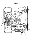
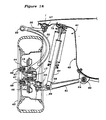
- Figure 1 is a cross sectional view taken along a generally vertically extending plane through one wheel of a motor vehicle having a suspension system constructed in accordance with an embodiment of the invention.
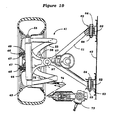
- Figure 2 is top plan view with portions shown in section, of the suspension system.
- Figure 3 is a view looking generally in the direction of the arrow 3 in the Figure 1 and shows the pivotal connection between the lower suspension arm and the vehicle.
- Figure 4 is a cross sectional view taken along the line 4-4 of Figure 1 and shows the connection between the lower arm and the suspension element.
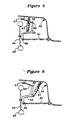
- Figure 5 is a partially schematic elevational view looking in the same direction as Figure 1 and shows another embodiment of the invention.
- Figure 6 is a schematic view, in part similar to Figure 5, and shows another embodiment of the invention.
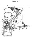
- Figure 7 is a cross sectional view, in part similar to Figure 1, and shows a further embodiment of the invention.
- Figure 8 is a top plan view, with portions broken away, of the embodiment of Figure 7.
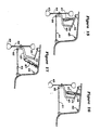
- Figure 9 is a schematic view, in part similar to Figure 7, and shown yet another embodiment of the invention.
- Figure 10 is a schematic view, in part similar to Figure 9, and shows a further embodiment of the invention.
- Figure 11 is a schematic view, in part similar to Figures 9 and 10, and shows a still further embodiment of the invention.
- Figure 12 is a schematic view, in part similar to Figures 9 through 11, showing a further embodiment of the invention.
- Figure 13 is a schematic view, in part similar to Figures 9 through 12, and shows another embodiment of the invention.
- Figure 14 is a schematic view, in part similar to Figures 9 through 13, and shows a still further embodiment.
- Figure 15 is a schematic view, in part similar to Figures 9 through 14, and shows another embodiment.
- Figure 16 is a schematic view, in part similar to Figures 9 through 15, showing yet another embodiment of the invention.
- Figure 17 is a further schematic view of yet another embodiment of the invention, in part similar to Figures 9 through 16.
- Figure 18 is a cross sectional view, in part similar to Figures 1 and 7, and shown yet another embodiment of the invention.
- Figure 19 is a top plan view of the embodiment of Figure 18, with portions shown in section.
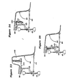
- Figure 20 is a schematic view, in part similar to Figure 18, showing another embodiment of the invention.
- Figure 21 is a schematic view, in part similar to Figure 20, showing yet another embodiment of the invention.
- Figure 22 is a schematic view, in part similar to Figures 20 and 21, showing a further embodiment of the invention.
- Figure 23 is a schematic view, in part similar to Figures 20 through 22, and shows yet another embodiment of the invention.
- Figure 24 is a schematic view, in part similar to Figures 20 through 23, showing yet another embodiment of the invention.
- Figure 25 is a schematic view, in part similar to Figures 20 through 24, showing a still further embodiment of the invention.
- Figure 26 is a schematic view, in part similar to Figures 20 through 25, and shows yet another embodiment of the invention.
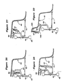
- Figure 27 is a schematic view, in part similar to Figures 20 through 26, and shows another embodiment of the invention.
- Figure 28 is a schematic view, in part similar to Figures 20 through 27, and shows yet another embodiment of the invention.
- Figure 29 is a schematic view, in part similar to Figures 20 through 28, and shows yet another embodiment of the invention.
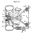
- Figure 30 is a cross section view, in part similar to Figures 1, 7 and 18 and shows a still further embodiment of the invention.
- Figure 31 is a top plan view, with portions shown in section, of the embodiment of Figure 30.
- Figure 32 is a top plan view, with portions shown in section, in part similar to Figure 31, and shows a still further embodiment of the invention.
- Figure 33 is partial top plan view, in part similar to Figures 31 and 32, and shows yet another embodiment of the invention.
- Figure 34 is partial top plan view, in part similar to Figures 31 through 33, showing another embodiment of the invention.
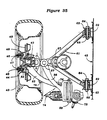
- Figure 35 is top plan view, in part similar to Figure 8, and shows another embodiment.
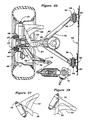
- Figure 36 is top plan view, in part similar to Figure 19, and shows yet another embodiment of the invention.
- Figure 37 is a partial view, in part similar to Figure 36, showing yet another embodiment of the invention.
- Figure 38 is a partial view, in part similar to Figure 36 and 37, and shows yet further embodiment of the invention.
- a front wheel suspension for a motor vehicle is identified generally by the reference numeral 41.
- the wheel suspension is that of the left front wheel of a motor vehicle which wheel is steered. This is because the invention has particular utility with the independent suspension for the steered front wheels of a motor vehicle. It is to be understood, however, that the invention may be utilized in conjunction with independent rear wheel suspensions and has particular utility where such rear wheels are also steered. The invention can also be utilized in conjunction with non-steered wheels.
- the vehicle with which the suspension 41 is associated is shown partially and is identified by the reference numeral 42.
- the vehicle 42 has a unitized construction and thus has no separate frame. It should be readily apparent to those skilled in the art how the invention can be employed in conjunction with frame type vehicles.
- a front tire 43 is mounted in a known manner on a front wheel 44.
- the wheel 44 is, in turn, affixed to a front axle 45 by means of studs 46 and nuts 47 in a known manner.
- the studs 46 are pressed into a flange 48 of the axle 45 and also affixed a front brake rotor 49 for rotation with the front wheel 44.
- a disc brake assembly (not shown) is operative with the brake rotor 49 for braking the front wheel 44 and tire 43.
- the axle 45 is journaled by means of an anti-friction bearing 51 in a hub portion 52 of an axle carrier, indicated generally by the reference numeral 53.
- the axle carrier 53 has a bifurcated upper portion consisting of inwardly extending arms 54 that are pivotally connected by means of pin type joints 55 to a pair of inwardly facing arm sections of a Y-shape upper arm 56.
- the pivotal connection formed by the joints 55 extends substantially parallel to the longitudinal axis of the motor vehicle and specifically its body 42 when the wheel 44 and tire 43 are in their straight ahead positions.
- the upper arm 56 is connected by means of a ball joint 57 to the body 53 and specifically an upper portion of the fender apron 58 thereof. This is adjacent the hood 59 of the vehicle body.
- the ball joint 57 permits the upper arm 56 to pivot about an axis that is parallel to the longitudinal center line of the vehicle for suspension movement and also to rotate about an axis 1 for steering movement, in a manner to be described.
- a generally Y-shaped lower arm 61 has a bifurcated end which has trunnions or bushings 62 which are pivotally supported within a pair of brackets 63 affixed to the body 42 by means of pivot bolts 64 and nuts 65. These pivot axes are parallel to the pivot axis 55 of the upper arm 53 when the front wheel 44 and tire 43 are in their straight ahead positions.
- a ball joint 66 is carried at the outer end of the lower arm 61 and provides a universal pivot connection to the axle carrier 53.
- the ball joint 66 is aligned along the axis 1 with the ball joint 57 so as to provide a generally vertically extending steering axis for the front wheel 44 and tire 43.
- the suspension movement of the front wheel 44 and tire 43 is controlled by a strut type combined shock absorber and spring assembly, generally indicated by the reference numeral 67 and hereinafter referred to as a "suspension element".
- the housing assembly 68 of this suspension unit is pivotally connected by means of a pivot bolt 69 and nut 71 through an intermediate bushings 71 to the lower arm 61.
- the upper end and specifically the piston rod of the suspension unit is connected to the fender apron 58 by a mounting assembly 72.
- a steering gear box 73 ( Figure 2) is carried by the vehicle body 42 and may be of the rack and pinion type which controls a steering link 74 that is connected by a pivotal connection 75 to a steering arm 76 formed integrally the axle carrier 53 for the steering movement of the front wheel 44 and front tire 43.
- the suspension unit 67 was loaded between the lower arm 61 and the body 42 with the point of loading being spaced inboard from the ball joint 57 of the upper arm 56 and outboard of the pivotal connection 55 between the upper arm 56 and the axle carrier 54.
- Other locations for the suspension unit are possible and Figures 5 and 6 show such other locations.
- the front wheel suspension system is substantially the same as previously described and only the location of the suspension unit 67 and its loading differs, only schematic views are believed to be necessary in order to show these differences.
- FIG. 6 shows another embodiment which is similar to the embodiment of Figure 5 but wherein the suspension unit 67 is connected to the axle carrier 53 on its inboard side and is pivotally connected to the body 42 inboard of both of the pivotal connections 57 and 55 of the upper arm 56.
- the upper arm 56 has been described as a bifurcated arm having a single ball joint pivotal connection to the body 42 and a double pivotal connection to the axle carrier 54. It is possible to employ a non-bifurcated arm that only has a single pivotal connection to the axle carrier 56 and Figures 7 and 8 show such an embodiment.
- the single pivotal connection 55 is elongated from the shorter split connections of the previously described embodiment. In all other regards, this embodiment is the same as those previously described and, for that reason, common reference numerals have been employed to identified common parts and further description is believed to be unnecessary.
- Figures 9 through 17 show a variety of alternative mounting arrangements for the suspension units employing a construction of the basic type shown in Figures 7 and 8. Because of the incorporation of this suspension system, the alternate suspension unit locations can be shown in schematic views and Figures 9 through 17 are such schematic views. In these schematic views, components which are the same in function as those previously described have been identified by the same reference numerals for obvious reasons.
- the suspension unit 67 is loaded between the lower arm 61 and an extension 101 of the upper arm so that the suspension unit 67 is positioned inboard of both the upper arm 56 and the axle carrier 53.
- the suspension unit 67 is loaded between the upper arm 56 and the body 42 and specifically within a spring tower 102 formed in the body 42.
- the suspension unit 67 is disposed at an angle and is loaded between the lower arm 61 and the axle carrier 53.
- the embodiment of Figure 12 is similar to the embodiment of Figure 9 in that the suspension unit 67 is loaded to an extension 101 of the upper arm 56. In this embodiment, however, the suspension element 67 reacts against the body 42 and specifically within a spring well 102 formed therein like the well 102 of the embodiment of Figure 10.
- the embodiment of Figure 13 also employs an extension 101 of the upper arm 56 for loading the suspension unit 67. However, in this embodiment the suspension unit 67 is loaded between this upper arm extension 101 and the axle carrier 53.
- Figure 14 shows an embodiment wherein the suspension unit 67 is loaded between the lower arm 61 and the upper arm 56 between the opposite pivotal connections of both the lower and upper arms.
- the suspension unit 67 is loaded between the axle carrier 43 and the upper arm 56. In this embodiment, the suspension unit 67 is located on the outboard side of the axle carrier 43.
- Figure 16 shows a similar embodiment but in this embodiment the suspension unit 67 is located directly between the outboard side of the axle carrier 43 and it loaded between the axle carrier 43 and the body 42.
- the embodiment of Figure 17 is similar to the embodiment of Figure 16 in that the suspension unit 67 is loaded between the axle carrier 43 and the body 42. In this embodiment, however, the suspension unit 67 is located inboard of the axle carrier 43 rather than outboard as in the embodiment of Figure 16.
- the upper arm 56 has been disposed so that its pivotal connection 57 to the body 42 is disposed outboard of its pivotal connection 55 to the axle carrier 54.
- Figures 18 and 19 show another embodiment of the invention which is generally the same as the previously described embodiments.
- the upper arm 56 which is bifurcated like the embodiments of Figures 1 through 7 has the ball joint pivotal connection 56 inboard of the pivotal connection 55 to the axle carrier 53.
- the axle carrier 53 is provided with a curve portion as clearly shown in Figures 18 and 19 so that the pivotal connection 55 to the outboard end of the upper arm 56 actually lies above the front wheel and tire 44, 43.
- This construction also permits the use of a single pivot pin 55 for the connection to both ends of the upper arm 56 and the upper arm 56 can be elongated rather than bifurcated as clearly shown in Figure 19.
- this embodiment is the same as those previously described and has the same advantages thereof.
- the suspension unit 67 is loaded between the lower arm 61 and an extension 101 of the upper arm 56 so as to place it inboard of the axle carrier 53.
- the suspension unit 67 is located in a spring well or tower 102 formed in the body 42 above the upper arm 56 and above the front wheel and tire 44, 43.
- the suspension unit 67 is located inboard of the axle carrier 53 and is loaded between the axle carrier 53 and the lower arm 61.
- the suspension unit 67 is located inboard and is loaded between and extension 101 of the upper arm 56 and the body 42.
- a spring tower 102 is provided for containing the suspension unit 67 in this embodiment.
- the suspension unit is loaded between an extension 101 of the upper arm 56 and the axle carrier 53 so as to be positioned inboard.
- the suspension unit 67 is loaded between the upper arm 56 and the lower arm 61 but without any extension of the upper arm. As a result, the suspension unit crosses across the axle carrier 53 to accommodate this location.
- the suspension unit 67 is positioned outboard of the axle carrier 53 and is loaded between the axle carrier 53 and the upper arm 56.
- the suspension unit 67 is positioned between the inboard side of the axle carrier 53 and is loaded between the axle carrier 53 and the body 42.
- the embodiment of Figure 28 loads the suspension unit 67 between the lower arm 61 and the body 42 and the suspension unit is positioned inboard of the axle carrier 53.
- axle carrier 53 is provided with an extension 105 and the suspension unit 67 is loaded between this extension 105 and the body 42.
- a spring tower 102 is provided in the body 42 so as to enclose the suspension unit 67.
- the pivotal connection 55 between the upper arm 56 and the axle carrier 53 has been disposed in a direction that extends generally parallel to the longitudinal axis of the associated vehicle when the front wheel 44 and tire 43 are in their straight ahead position.
- Figures 30 and 31 shown an embodiment which is similar to the embodiment of Figures 7 and 8 in that the upper arm 56 is not bifurcated.
- the pivotal connection 55 between the axle carrier 53 and the inboard and of the upper arm 56 extends perpendicularly to the direction of the embodiment of Figure 7 when the wheel 44 and tire 43 are in their straight ahead position.
- this embodiment is the same as that of Figures 7 and 8 and, for that reason, the same reference numerals have been employed to identify the same components.
- Figures 7 through 17 and Figures 30 and 31 the single non-bifurcated upper arm 53 has been disposed on the forward side of the front suspension system.
- Figures 32 through 35 show other embodiments of the invention that have generally the same relationships but wherein the single upper arm 53 is disposed on the rear side of the suspension.
- the pivotal connection 55 is in the same orientation as the embodiment of Figures 30 and 31, however, it is on the rear side of the front suspension rather than on the forward side.
- Figure 35 shows an embodiment similar to Figures 7 and 8 but, again, the arm is to the rear rather than to the front.
- pivot axis 55 has been disposed either parallel to the longitudinal center line of the vehicle when the front wheel 44 and tire 43 are in their straight ahead position or perpendicular to it.
- Figures 33 and 34 show such other angular relationships.
- Figure 37 shows another embodiment of the invention that is similar to the embodiment of Figures 18 and 19.
- the axle carrier 53 was generally bifurcated and had two spaced apart pivotal connections to the upper arm 56.
- Figure 37 shown an embodiment which is generally the same but wherein the bifurcation of the axle carrier 53 is not required.
- the pivotal axis 55 extends generally parallel to the longitudinal axis of the vehicle when the wheel 44 and tire 43 are in their straight ahead positions.
- Figures 37 and 38 show such alternative locations.
- the single arm may be disposed rearwardly of the wheel axis rather than forwardly of it as shown in Figures 36 through 38 and at any desired angular relationship.
Landscapes
- Engineering & Computer Science (AREA)
- Mechanical Engineering (AREA)
- Vehicle Body Suspensions (AREA)
Applications Claiming Priority (4)
| Application Number | Priority Date | Filing Date | Title |
|---|---|---|---|
| JP1062/90 | 1990-01-09 | ||
| JP106290 | 1990-01-09 | ||
| JP22841890A JPH03253413A (ja) | 1990-01-09 | 1990-08-31 | 車両の懸架装置 |
| JP228418/90 | 1990-08-31 |
Publications (2)
| Publication Number | Publication Date |
|---|---|
| EP0437255A2 true EP0437255A2 (fr) | 1991-07-17 |
| EP0437255A3 EP0437255A3 (en) | 1991-12-27 |
Family
ID=33454697
Family Applications (1)
| Application Number | Title | Priority Date | Filing Date |
|---|---|---|---|
| EP19910100243 Withdrawn EP0437255A3 (en) | 1990-01-09 | 1991-01-09 | Suspension mechanism for vehicles |
Country Status (3)
| Country | Link |
|---|---|
| US (1) | US5114176A (fr) |
| EP (1) | EP0437255A3 (fr) |
| CA (1) | CA2033854A1 (fr) |
Cited By (4)
| Publication number | Priority date | Publication date | Assignee | Title |
|---|---|---|---|---|
| US5286052A (en) * | 1992-11-23 | 1994-02-15 | Chrysler Corporation | Vehicle suspension with floating upper arm |
| EP0785098A1 (fr) * | 1996-01-19 | 1997-07-23 | Jaguar Cars Limited | Suspensions pour véhicules |
| NL1002596C2 (nl) * | 1996-03-13 | 1997-09-17 | Transport Industry Dev Centre | Voertuig alsmede wielophanging voor een dergelijk voertuig. |
| WO2005051687A1 (fr) * | 2003-11-26 | 2005-06-09 | Bayerische Motoren Werke Aktiengesellschaft | Suspension independante pour une roue de vehicule automobile en particulier non directrice |
Families Citing this family (11)
| Publication number | Priority date | Publication date | Assignee | Title |
|---|---|---|---|---|
| US5498019A (en) | 1994-12-15 | 1996-03-12 | Adato; Henri | Suspension system for controlling lateral displacement of a wheel |
| US5782484A (en) * | 1996-05-14 | 1998-07-21 | Chrysler Corporation | Short long arm independent suspension |
| DE19717069C2 (de) * | 1997-04-23 | 1999-09-23 | Daimler Chrysler Ag | Einzelradaufhängung für gelenkte Räder von Kraftfahrzeugen, insbesondere Personenkraftwagen |
| US5954352A (en) * | 1998-08-17 | 1999-09-21 | Ford Global Technologies, Inc. | Rear suspension for a motor vehicle |
| DE20023579U1 (de) * | 1999-05-03 | 2004-12-16 | Dr.Ing.H.C. F. Porsche Ag | Radaufhängung für eine Vorderachse eines Kraftfahrzeuges |
| JP3843209B2 (ja) * | 2000-03-15 | 2006-11-08 | 本田技研工業株式会社 | 鞍乗り型車輌 |
| JP2001295876A (ja) | 2000-04-10 | 2001-10-26 | Yamaha Motor Co Ltd | 車両用油圧式緩衝器 |
| JP4844026B2 (ja) * | 2005-07-12 | 2011-12-21 | 日産自動車株式会社 | 車両用サスペンション装置 |
| DE102005044222A1 (de) * | 2005-09-16 | 2007-08-30 | Audi Ag | Unabhängige Radaufhängung für die Hinterräder von Kraftfahrzeugen |
| IL178060A (en) * | 2006-09-13 | 2010-06-30 | Davidovitch J | Vertical non- guided vehicle suspension |
| DE102008040212A1 (de) * | 2008-07-07 | 2010-01-14 | Zf Friedrichshafen Ag | Radaufhängung für ein Fahrzeug |
Family Cites Families (6)
| Publication number | Priority date | Publication date | Assignee | Title |
|---|---|---|---|---|
| NL257594A (fr) * | 1959-11-06 | |||
| US4526249A (en) * | 1983-05-25 | 1985-07-02 | Parker James G | Front suspension system for a motorcycle |
| DE3442682A1 (de) * | 1984-11-23 | 1986-06-05 | Audi AG, 8070 Ingolstadt | Unabhaengige radaufhaengung fuer kraftfahrzeuge |
| US4753455A (en) * | 1986-07-15 | 1988-06-28 | Nissasn Motor Co., Ltd. | Double link type suspension system |
| JPH0659769B2 (ja) * | 1987-10-19 | 1994-08-10 | 日産自動車株式会社 | ダブルリンク式サスペンション装置 |
| IT1233435B (it) * | 1987-12-23 | 1992-03-31 | Cagiva Motor | Sospensione per la ruota anteriore di motociclette e simili. |
-
1991
- 1991-01-08 US US07/638,678 patent/US5114176A/en not_active Expired - Fee Related
- 1991-01-09 EP EP19910100243 patent/EP0437255A3/en not_active Withdrawn
- 1991-01-09 CA CA002033854A patent/CA2033854A1/fr not_active Abandoned
Cited By (5)
| Publication number | Priority date | Publication date | Assignee | Title |
|---|---|---|---|---|
| US5286052A (en) * | 1992-11-23 | 1994-02-15 | Chrysler Corporation | Vehicle suspension with floating upper arm |
| EP0785098A1 (fr) * | 1996-01-19 | 1997-07-23 | Jaguar Cars Limited | Suspensions pour véhicules |
| US6113120A (en) * | 1996-01-19 | 2000-09-05 | Jaguar Cars Limited | Vehicle suspension |
| NL1002596C2 (nl) * | 1996-03-13 | 1997-09-17 | Transport Industry Dev Centre | Voertuig alsmede wielophanging voor een dergelijk voertuig. |
| WO2005051687A1 (fr) * | 2003-11-26 | 2005-06-09 | Bayerische Motoren Werke Aktiengesellschaft | Suspension independante pour une roue de vehicule automobile en particulier non directrice |
Also Published As
| Publication number | Publication date |
|---|---|
| CA2033854A1 (fr) | 1991-07-10 |
| EP0437255A3 (en) | 1991-12-27 |
| US5114176A (en) | 1992-05-19 |
Similar Documents
| Publication | Publication Date | Title |
|---|---|---|
| US4799708A (en) | Off-road vehicle | |
| US5114176A (en) | Suspension mechanism for vehicles | |
| US4705128A (en) | Independent wheel suspension system having a differential pivotable about two axes | |
| US4834412A (en) | Motorcycle front wheel suspension device | |
| US4538831A (en) | Suspension for vehicles | |
| US3630303A (en) | Front suspension for a front drive vehicle | |
| US5286052A (en) | Vehicle suspension with floating upper arm | |
| US5405162A (en) | Vehicle suspension system for steerable wheel | |
| US4911466A (en) | Constant camber suspension | |
| EP0182606B1 (fr) | Suspension arrière à roues indépendantes | |
| US4923209A (en) | Wheel suspension for a powered front axle of a motor vehicle | |
| EP0323414B1 (fr) | Suspension arrière pour véhicule automobile à roues indépendantes du type à bras longitudinaux | |
| US3177965A (en) | Link type independent wheel suspension for vehicles | |
| US3462168A (en) | Independent wheel suspension for steerable wheels of motor vehicles,especially passenger motor vehicles | |
| US4720121A (en) | Rear suspension for vehicle | |
| US4902033A (en) | Double wishbone rear suspension | |
| US4478430A (en) | Strut type vehicle suspension mechanism | |
| US6719311B2 (en) | Vehicle steering assembly | |
| US4832364A (en) | Rear suspension for vehicle | |
| US4564213A (en) | Strut type vehicle suspension mechanism | |
| JP2831347B2 (ja) | 荒地走行用車輛の前輪独立懸架装置 | |
| EP0589273B1 (fr) | Train arrière à roues indépendantes pour véhicules automobiles | |
| EP0457296A2 (fr) | Suspension à deux bras pour une roue motrice et directrice de véhicule | |
| JPS604804Y2 (ja) | 自動車の後輪懸架装置 | |
| JPS6029309A (ja) | 自動車のリヤサスペンション |
Legal Events
| Date | Code | Title | Description |
|---|---|---|---|
| PUAI | Public reference made under article 153(3) epc to a published international application that has entered the european phase |
Free format text: ORIGINAL CODE: 0009012 |
|
| AK | Designated contracting states |
Kind code of ref document: A2 Designated state(s): DE ES FR GB IT |
|
| PUAL | Search report despatched |
Free format text: ORIGINAL CODE: 0009013 |
|
| AK | Designated contracting states |
Kind code of ref document: A3 Designated state(s): DE ES FR GB IT |
|
| 17P | Request for examination filed |
Effective date: 19920227 |
|
| 17Q | First examination report despatched |
Effective date: 19920811 |
|
| STAA | Information on the status of an ep patent application or granted ep patent |
Free format text: STATUS: THE APPLICATION IS DEEMED TO BE WITHDRAWN |
|
| 18D | Application deemed to be withdrawn |
Effective date: 19921222 |