EP0437262B2 - Verfahren zur präventiven Konsolidierung des Bodens beim Untertagebau - Google Patents
Verfahren zur präventiven Konsolidierung des Bodens beim Untertagebau Download PDFInfo
- Publication number
- EP0437262B2 EP0437262B2 EP91100265A EP91100265A EP0437262B2 EP 0437262 B2 EP0437262 B2 EP 0437262B2 EP 91100265 A EP91100265 A EP 91100265A EP 91100265 A EP91100265 A EP 91100265A EP 0437262 B2 EP0437262 B2 EP 0437262B2
- Authority
- EP
- European Patent Office
- Prior art keywords
- tube
- soil
- rod
- hollow
- excavation
- Prior art date
- Legal status (The legal status is an assumption and is not a legal conclusion. Google has not performed a legal analysis and makes no representation as to the accuracy of the status listed.)
- Expired - Lifetime
Links
- 239000002689 soil Substances 0.000 title claims abstract description 34
- 238000000034 method Methods 0.000 title claims abstract description 28
- 230000003449 preventive effect Effects 0.000 title abstract description 4
- 238000007596 consolidation process Methods 0.000 title abstract 2
- 238000005065 mining Methods 0.000 title description 3
- 238000009412 basement excavation Methods 0.000 claims abstract description 14
- 239000000203 mixture Substances 0.000 claims abstract description 14
- 238000002347 injection Methods 0.000 claims abstract description 9
- 239000007924 injection Substances 0.000 claims abstract description 9
- 239000007788 liquid Substances 0.000 claims abstract description 5
- 239000011440 grout Substances 0.000 claims description 19
- 230000003019 stabilising effect Effects 0.000 claims description 7
- 229910000831 Steel Inorganic materials 0.000 claims description 6
- 239000010959 steel Substances 0.000 claims description 6
- 239000000463 material Substances 0.000 claims description 3
- 238000003491 array Methods 0.000 claims description 2
- 238000005553 drilling Methods 0.000 abstract description 10
- 230000001681 protective effect Effects 0.000 abstract description 4
- 230000002787 reinforcement Effects 0.000 abstract description 2
- 238000000605 extraction Methods 0.000 abstract 1
- 239000012530 fluid Substances 0.000 description 2
- 238000012856 packing Methods 0.000 description 2
- 230000003014 reinforcing effect Effects 0.000 description 2
- 230000006641 stabilisation Effects 0.000 description 2
- 241000251468 Actinopterygii Species 0.000 description 1
- 240000000491 Corchorus aestuans Species 0.000 description 1
- 235000011777 Corchorus aestuans Nutrition 0.000 description 1
- 235000010862 Corchorus capsularis Nutrition 0.000 description 1
- 229910001294 Reinforcing steel Inorganic materials 0.000 description 1
- 230000001174 ascending effect Effects 0.000 description 1
- 238000005452 bending Methods 0.000 description 1
- 239000004568 cement Substances 0.000 description 1
- 239000004567 concrete Substances 0.000 description 1
- 239000011796 hollow space material Substances 0.000 description 1
- 239000002184 metal Substances 0.000 description 1
- 239000004570 mortar (masonry) Substances 0.000 description 1
- 238000011084 recovery Methods 0.000 description 1
- 238000007789 sealing Methods 0.000 description 1
- 239000007787 solid Substances 0.000 description 1
- 238000006467 substitution reaction Methods 0.000 description 1
- 238000011282 treatment Methods 0.000 description 1
Images

Classifications
-
- E—FIXED CONSTRUCTIONS
- E02—HYDRAULIC ENGINEERING; FOUNDATIONS; SOIL SHIFTING
- E02D—FOUNDATIONS; EXCAVATIONS; EMBANKMENTS; UNDERGROUND OR UNDERWATER STRUCTURES
- E02D3/00—Improving or preserving soil or rock, e.g. preserving permafrost soil
- E02D3/12—Consolidating by placing solidifying or pore-filling substances in the soil
-
- E—FIXED CONSTRUCTIONS
- E21—EARTH OR ROCK DRILLING; MINING
- E21D—SHAFTS; TUNNELS; GALLERIES; LARGE UNDERGROUND CHAMBERS
- E21D20/00—Setting anchoring-bolts
- E21D20/02—Setting anchoring-bolts with provisions for grouting
Definitions
- the object of the present invention is a method for preventive stabilisation of the soil for underground minings by means of the so-called techinique of the protective umbrella, in particular for unstable kinds of soil.
- the present techniques for the preventive stabilisation of underground minings in particularly unstable soil there is one known as the "protective umbrella", which consists of inserting into the soil arrays of steel tubes provided with nonreturn valves for executing injections of stabilising and consolidating mixtures, mainly cement grout.
- the tubes are disposed like an umbrella, protecting the vault of an intended tunnel excavation so as to allow excavation of parts of it within a limited length.
- the excavation of the parts of the tunnel is alternated with the execution of said umbrellas of steel tubes that is combined with the soil stabilising injections.
- the technique that is normally used comprises a phase in which the soil is drilled with a temporary and recoverable steel tubular casing; in a second phase a steel tube is fitted inside the casing.
- This tube is provided with holes at regular intervals and has elastic sleeves, in correspondence of each hole, that act as nonreturn valves when the stabilising mixtures are injected through the tube.
- a following phase is that of the recovery of the provisory casing, after which a grout sheating is formed, having a controlled maximum compressive strength, for sealing the injecting tube into the soil.
- the stabilising mixtures are injected into the soil, through the holes of the tube, breaking the sheating.
- An alternative technique is to execute the provisory casing with the techiniques used for carrying out jet-grouting columnar treatments, that form columns of consolidated soil by injecting high pressurized grout mixtures by means of a tubular rod provided with nozzles for letting the mixture out and with a piercing bit that is made to rotate and is extracted and pushed into the ground with a controlled speed.
- Traditional jet grouting is used to execute substantially vertical columns by drilling the soil by means of a hollow drill pipe having a piercing bit at its bottom end and a plurality of nozzles proximate thereto. After drilling operations are completed, grout injection is carried out in an ascending phase, beginning from the bottom of the borehole.
- the jet grouting technique cannot be employed conveniently for executing substantially horizontal columns because problems arise if the grout feeding is interrupted due to drill pipe damages or substitution of parts.
- the walls of the hole tend to collapse rather easily, owing to the fact that the grout in a substantially horizontal borehole cannot sustain the walls as it does in vertical boreholes.
- the function of the consolidated columns is to temporarily sustain the soil above them while a tunnel is dug out underneath, the columns must be reinforced to resist shear and bending stresses that occur when archings are placed underneath them.
- the metal reinforcement can be fitted only when the column is formed. Two alternative methods can be used:
- Document JP-A-58-228558 discloses a method in which a borehole is excavated first, and after that, a planking pipe is installed in the hole. Then, a grout pipe with packings is inserted inside the planking pipe. The packings are then inflated and a grout is injected at low pressure through the grout pipe and discharge holes of the planking pipe so as to fill the space between the excavated hole and the planking pipe. Finally, the grout pipe is pulled off, and the planking pipe is filled with mortar. This method suffers from the above drawbacks, and is not suitable for high pressure grout injections.
- Document JP-A-55-64395 relates to a method for executing vertical reinforcing concrete pillars by means of an apparatus that comprises a hollow grout delivering shaft having a bottom excavating blade.
- the shaft is located inside a cylinder having a bottom agitating blade and both the shaft and the cylinder are rotated in opposite directions.
- This method is not suitable for executing substantially horizontal columns that are required for tunnelling with the protective umbrella technique.
- Document DE-A-3447872 disdoses a soil stabilising method for tunnelling in which a plurality of boreholes are obtained in the soil about an arc of a circle outlining a tunnel that has to be dug out.
- a tube provided with valves and surrounded by a jute bag is slipped in each borehole, and an injection packer is inserted in each tube for injecting a fluid mixture that fills the bag, presses the walls of the borehole and infiltrates in the surrounding soil.
- the fluid mixture in the bag and the portion that has penetrated in the soil consolidates and stabilises the soil. Also this method suffers from the same inconveniences as JP-A-58-228558, and is incompatible with high pressure grout injections.
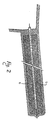
- a straight metallic hollow tube 1, preferably made out of steel, and a straight hollow rod 2 are used.
- Said rod has a diameter that is smaller than the one of the tube 1 and a double rotary drilling unit, which is not shown in the figures, is used to rotate both the tube 1 and the rod 2.
- the rod 2 is provided at one end with a boring tool indicated as a whole with 3 which comprises a traditional piercing bit 4 and near this there are nozzles that are distributed radially on the rod and that communicate with the outside.
- a boring tool indicated as a whole with 3 which comprises a traditional piercing bit 4 and near this there are nozzles that are distributed radially on the rod and that communicate with the outside.
- the tools that are hereby mentioned are not described in details, as they are traditional and already known.
- the rod 2 In operating conditions, the rod 2 is slipped into the tube 1 and is kept coaxial with respect to the tube by the rotary drilling unit.
- the boring tool 3 is positioned and kept outside the front end of the tube and is directed perpendicular to the soil that has to be stabilised.
- the rod 2 and the tube 1 are both rotated by the rotary drilling unit for piercing the soil and proceed this way.
- the rotary drilling head forces the rod 2 and the tube 1 to rotate at the same time but in the opposite directions of rotation. For example the rod 2 is rotated clockwise while the tube 1 is being rotated counter-clockwise.
- the material that is excavated by the drilling operation is conveyed towards the outside through the annular hollow space 5 between the rod 2 and the inner annular surface of tube 1.
- high pressurized liquid mixture is injected through the rod, removing the finest part of soil.
- the mixture flows through the nozzles forming a column 6 of soil and grout mixture around the tube 1 that later on will stiffen.
- the rod 2 When the right length of the column 6 is obtained, the rod 2 has to be pulled out of the tube 1 and taken away whereas the tube 1 may be left in the soil so to form columns of reinforced soil.
- the tube 1 and the rod 2 are forced to advance and spin according to prefixed parameters in a direction substantially oblique compared with the level line so that columns are formed in such a way that they partially lie one over the other like the scales of a fish.
Landscapes
- Engineering & Computer Science (AREA)
- Structural Engineering (AREA)
- Life Sciences & Earth Sciences (AREA)
- Mining & Mineral Resources (AREA)
- General Life Sciences & Earth Sciences (AREA)
- Paleontology (AREA)
- Soil Sciences (AREA)
- Environmental & Geological Engineering (AREA)
- Agronomy & Crop Science (AREA)
- Civil Engineering (AREA)
- General Engineering & Computer Science (AREA)
- Geochemistry & Mineralogy (AREA)
- Geology (AREA)
- Consolidation Of Soil By Introduction Of Solidifying Substances Into Soil (AREA)
- Walking Sticks, Umbrellas, And Fans (AREA)
- Excavating Of Shafts Or Tunnels (AREA)
Claims (2)
- Verfaren zum stabilisieren des bodens zur Tunnelasschachtung durch Einbringen von Gruppen von Stahlrohren mit Ventilen in den Boden zum Injizieren von Zement in den Boden um die beabsichtigte Tunnelausschactung
dadurch gekennzeichnet, daßein hohles Rohr (1) an einer Ausschachtungsstelle angeordnet wird;eine hohle Stange (2) mit Düsen koaxial in dem hohlen Rohr (1) angeordnet wird, so daß ein ringförmiger Zwischenraum (5) zwischen der Stange (2) und dem Rohr (1) gebildet wird, wobei in die hohle Stange eine Bohrwerkzeug (3) an deren einem Ende eingesetzt wird;das hohle Rohr (1) und die hohle Stange (2) gedreht werden, um Material aus der Ausschactungsstelle mittels des Bohrwerkzeug (3) auszuschachten;ein Hochdruck-Flüssiggemisch durch die hohle Stange (2) in die Ausschachtungsstelle nahe dem Bohrwerkzeug (3) während der Drehung des hohlen Rohres (1) und der hohlen Stage (2) durch radial verteilten Düsen, gleichzeitig injiziert wird, so daß der Durchmesser der Ausschachtungsstelle verbreitet und der ein Teil des feinkörnigsten Anteils des ausgebaggerten Bodens aus der Ausschachtungsstelle über den ringförmigen Zwischenraum (5) entfernt wird, und das Flüssiggemisch mit dem verbleibenden Anteil des ausgeschachteten Materials vermischt wird, um eine erhärtende Säule (6) des Bodens und des Flüssiggemisches, um das Rohr (1) hinter dem Bohrwerkzeug während der Bohrvorgang in dem Boden, zu bilden; undeine Stange (2) aus dem hohlen Rohr (1), nach der Erreichung der gewünschten Länge der Säule (6), entfernt wird. - Verfahren nach Anspruch 1,
dadurch gekennzeichnet, daß
während des Ausschachtens das Rohr (1) und die Stange (2) gleichzeitig vorgerückt und in entgegengesetzten Richtungen gedreht werden.
Applications Claiming Priority (2)
| Application Number | Priority Date | Filing Date | Title |
|---|---|---|---|
| IT00330690A IT1238428B (it) | 1990-01-11 | 1990-01-11 | Procedimento per il consolidamento preventivo degli scavi di gallerie mediante la tecnica dell'ombrello protettivo |
| IT330690 | 1990-01-11 |
Publications (3)
| Publication Number | Publication Date |
|---|---|
| EP0437262A1 EP0437262A1 (de) | 1991-07-17 |
| EP0437262B1 EP0437262B1 (de) | 1994-07-27 |
| EP0437262B2 true EP0437262B2 (de) | 1998-01-14 |
Family
ID=11104658
Family Applications (1)
| Application Number | Title | Priority Date | Filing Date |
|---|---|---|---|
| EP91100265A Expired - Lifetime EP0437262B2 (de) | 1990-01-11 | 1991-01-10 | Verfahren zur präventiven Konsolidierung des Bodens beim Untertagebau |
Country Status (4)
| Country | Link |
|---|---|
| EP (1) | EP0437262B2 (de) |
| AT (1) | ATE109234T1 (de) |
| DE (1) | DE69103027T3 (de) |
| IT (1) | IT1238428B (de) |
Families Citing this family (3)
| Publication number | Priority date | Publication date | Assignee | Title |
|---|---|---|---|---|
| JPH089863B2 (ja) * | 1991-08-14 | 1996-01-31 | 株式会社エヌ、アイ、テイ | 全角度地盤改良体造成工法及びその装置 |
| RU2468207C1 (ru) * | 2011-04-05 | 2012-11-27 | Государственное образовательное учреждение высшего профессионального образования "Санкт-Петербургский государственный горный институт имени Г.В. Плеханова (технический университет)" | Способ крепления почвы горных выработок |
| CN104564113B (zh) * | 2015-01-15 | 2016-08-17 | 山东科技大学 | 巷道围岩纤维浆液注浆加固的施工方法 |
Family Cites Families (2)
| Publication number | Priority date | Publication date | Assignee | Title |
|---|---|---|---|---|
| IT1208123B (it) * | 1983-04-19 | 1989-06-06 | Fondedile Spa | Colonna in conglomerato realizzata nel terreno in situ mediante immissione di materiali inerti durante la perforazione e contemporaneao successiva iniezione con opportuni leganti, procedimenti di esecuzione relativi |
| CH665878A5 (it) * | 1984-12-11 | 1988-06-15 | Rodio Found Eng Ltd | Procedimento per il consolidamento di terreno nello scavo di gallerie. |
-
1990
- 1990-01-11 IT IT00330690A patent/IT1238428B/it active IP Right Grant
-
1991
- 1991-01-10 EP EP91100265A patent/EP0437262B2/de not_active Expired - Lifetime
- 1991-01-10 AT AT91100265T patent/ATE109234T1/de not_active IP Right Cessation
- 1991-01-10 DE DE69103027T patent/DE69103027T3/de not_active Expired - Lifetime
Also Published As
| Publication number | Publication date |
|---|---|
| ATE109234T1 (de) | 1994-08-15 |
| DE69103027D1 (de) | 1994-09-01 |
| IT9003306A1 (it) | 1991-07-12 |
| EP0437262A1 (de) | 1991-07-17 |
| DE69103027T2 (de) | 1994-11-17 |
| DE69103027T3 (de) | 1998-06-10 |
| IT1238428B (it) | 1993-07-26 |
| EP0437262B1 (de) | 1994-07-27 |
| IT9003306A0 (it) | 1990-01-11 |
Similar Documents
| Publication | Publication Date | Title |
|---|---|---|
| KR20190023619A (ko) | 터널 굴착면 보강구조체 및 이를 이용한 터널 보강 방법 | |
| CN116113754A (zh) | 一种隧道盾构 | |
| US6120214A (en) | Process for constructing reinforced subterranean columns | |
| US3839871A (en) | Earthen dam repair | |
| KR101985267B1 (ko) | 슬라임 배출 억제용 그라우팅 장치 및 이를 이용한 제트 그라우팅공법 | |
| CA2456303C (en) | Continuous method of realization of underground tunnels including peripheral perforations | |
| US9181673B2 (en) | Tools and methods for constructing large diameter underground piles | |
| EP0437262B2 (de) | Verfahren zur präventiven Konsolidierung des Bodens beim Untertagebau | |
| US5152638A (en) | Process and apparatus for excavating tunnels | |
| JP3863320B2 (ja) | トンネル先受け工法 | |
| US5380127A (en) | Non-entry method of underground excavation in weak or water bearing grounds | |
| JP3450639B2 (ja) | ロックボルトの打設方法およびロックボルト打設機 | |
| JP2762935B2 (ja) | 水平モルタル杭構築工法 | |
| KR102917000B1 (ko) | 역순환 천공장치 및 이를 이용한 어스앵커 설치공법 | |
| JP3306460B2 (ja) | 杭打ち工法 | |
| WO1995015419A1 (en) | Ground boring device and method for constructing an underground wall using the same | |
| JP3455157B2 (ja) | 支保工の構築工法 | |
| JPH05321511A (ja) | 軟弱地盤における地中容器の築造方法 | |
| WO2000044994A1 (en) | Soil mixing process | |
| JP3735152B2 (ja) | トンネルの掘削方法 | |
| JPH06100080B2 (ja) | 大断面トンネルの施工方法及び地盤固化柱造成装置 | |
| Ressi di Cervia | New techniques in difficult ground tunneling | |
| KR20000030523A (ko) | 네일링공법 및 그 장치 | |
| JPH0427012A (ja) | アースアンカの施工方法 | |
| GB2221712A (en) | Forming piles in situ |
Legal Events
| Date | Code | Title | Description |
|---|---|---|---|
| PUAI | Public reference made under article 153(3) epc to a published international application that has entered the european phase |
Free format text: ORIGINAL CODE: 0009012 |
|
| AK | Designated contracting states |
Kind code of ref document: A1 Designated state(s): AT DE ES FR GB GR IT NL |
|
| 17P | Request for examination filed |
Effective date: 19911023 |
|
| 17Q | First examination report despatched |
Effective date: 19921015 |
|
| GRAA | (expected) grant |
Free format text: ORIGINAL CODE: 0009210 |
|
| AK | Designated contracting states |
Kind code of ref document: B1 Designated state(s): AT DE ES FR GB GR IT NL |
|
| PG25 | Lapsed in a contracting state [announced via postgrant information from national office to epo] |
Ref country code: ES Free format text: THE PATENT HAS BEEN ANNULLED BY A DECISION OF A NATIONAL AUTHORITY Effective date: 19940727 Ref country code: AT Effective date: 19940727 Ref country code: GR Free format text: LAPSE BECAUSE OF FAILURE TO SUBMIT A TRANSLATION OF THE DESCRIPTION OR TO PAY THE FEE WITHIN THE PRESCRIBED TIME-LIMIT Effective date: 19940727 Ref country code: NL Effective date: 19940727 |
|
| REF | Corresponds to: |
Ref document number: 109234 Country of ref document: AT Date of ref document: 19940815 Kind code of ref document: T |
|
| REF | Corresponds to: |
Ref document number: 69103027 Country of ref document: DE Date of ref document: 19940901 |
|
| ITF | It: translation for a ep patent filed | ||
| ET | Fr: translation filed | ||
| PG25 | Lapsed in a contracting state [announced via postgrant information from national office to epo] |
Ref country code: GB Effective date: 19950110 |
|
| NLV1 | Nl: lapsed or annulled due to failure to fulfill the requirements of art. 29p and 29m of the patents act | ||
| PLBI | Opposition filed |
Free format text: ORIGINAL CODE: 0009260 |
|
| 26 | Opposition filed |
Opponent name: BAUER SPEZIALTIEFBAU GMBH Effective date: 19950420 |
|
| GBPC | Gb: european patent ceased through non-payment of renewal fee |
Effective date: 19950110 |
|
| PLAW | Interlocutory decision in opposition |
Free format text: ORIGINAL CODE: EPIDOS IDOP |
|
| PLAW | Interlocutory decision in opposition |
Free format text: ORIGINAL CODE: EPIDOS IDOP |
|
| PUAH | Patent maintained in amended form |
Free format text: ORIGINAL CODE: 0009272 |
|
| STAA | Information on the status of an ep patent application or granted ep patent |
Free format text: STATUS: PATENT MAINTAINED AS AMENDED |
|
| 27A | Patent maintained in amended form |
Effective date: 19980114 |
|
| AK | Designated contracting states |
Kind code of ref document: B2 Designated state(s): AT DE ES FR GB GR IT NL |
|
| ITF | It: translation for a ep patent filed | ||
| ET3 | Fr: translation filed ** decision concerning opposition | ||
| PG25 | Lapsed in a contracting state [announced via postgrant information from national office to epo] |
Ref country code: IT Free format text: LAPSE BECAUSE OF NON-PAYMENT OF DUE FEES;WARNING: LAPSES OF ITALIAN PATENTS WITH EFFECTIVE DATE BEFORE 2007 MAY HAVE OCCURRED AT ANY TIME BEFORE 2007. THE CORRECT EFFECTIVE DATE MAY BE DIFFERENT FROM THE ONE RECORDED. Effective date: 20050110 |
|
| PLAB | Opposition data, opponent's data or that of the opponent's representative modified |
Free format text: ORIGINAL CODE: 0009299OPPO |
|
| PGRI | Patent reinstated in contracting state [announced from national office to epo] |
Ref country code: IT Effective date: 20091201 |
|
| PGFP | Annual fee paid to national office [announced via postgrant information from national office to epo] |
Ref country code: FR Payment date: 20100208 Year of fee payment: 20 |
|
| PGFP | Annual fee paid to national office [announced via postgrant information from national office to epo] |
Ref country code: DE Payment date: 20100107 Year of fee payment: 20 |
|
| PGRI | Patent reinstated in contracting state [announced from national office to epo] |
Ref country code: IT Effective date: 20091201 |
|
| PGFP | Annual fee paid to national office [announced via postgrant information from national office to epo] |
Ref country code: IT Payment date: 20100125 Year of fee payment: 20 |
|
| PGRI | Patent reinstated in contracting state [announced from national office to epo] |
Ref country code: IT Effective date: 20110616 |
|
| PG25 | Lapsed in a contracting state [announced via postgrant information from national office to epo] |
Ref country code: DE Free format text: LAPSE BECAUSE OF EXPIRATION OF PROTECTION Effective date: 20110110 |