EP0437364A2 - Procédé pour séparer des signaux électromagnétiques réfractés, des signaux réflectés dans les dispositifs de mesure électromagnétiques dans les puits - Google Patents
Procédé pour séparer des signaux électromagnétiques réfractés, des signaux réflectés dans les dispositifs de mesure électromagnétiques dans les puits Download PDFInfo
- Publication number
- EP0437364A2 EP0437364A2 EP91300175A EP91300175A EP0437364A2 EP 0437364 A2 EP0437364 A2 EP 0437364A2 EP 91300175 A EP91300175 A EP 91300175A EP 91300175 A EP91300175 A EP 91300175A EP 0437364 A2 EP0437364 A2 EP 0437364A2
- Authority
- EP
- European Patent Office
- Prior art keywords
- antenna
- signal
- polarization
- sonde
- transmitted
- Prior art date
- Legal status (The legal status is an assumption and is not a legal conclusion. Google has not performed a legal analysis and makes no representation as to the accuracy of the status listed.)
- Withdrawn
Links
Images

Classifications
-
- G—PHYSICS
- G01—MEASURING; TESTING
- G01V—GEOPHYSICS; GRAVITATIONAL MEASUREMENTS; DETECTING MASSES OR OBJECTS; TAGS
- G01V3/00—Electric or magnetic prospecting or detecting; Measuring magnetic field characteristics of the earth, e.g. declination, deviation
- G01V3/18—Electric or magnetic prospecting or detecting; Measuring magnetic field characteristics of the earth, e.g. declination, deviation specially adapted for well-logging
- G01V3/30—Electric or magnetic prospecting or detecting; Measuring magnetic field characteristics of the earth, e.g. declination, deviation specially adapted for well-logging operating with electromagnetic waves
Definitions
- the present disclosure sets out an approach for separating reflected signals from refracted signals in well borehole electromagnetic tools.
- a typical tool used in these circumstances can have a frequency as high as several Ghz down to the Mhz range, and even lower in frequency.
- they transmit an EM field into formations adjacent to a well borehole utilizing a magnetic dipole antenna either arranged parallel to the axis of the well or horizontally positioned transverse to the axis or a combination of antennas or axes.
- the normal circumstances in which this device is used involves transmission from a logging tool sonde through a mud cake or invaded zone.
- the problem referred to is found in all formations including those where a mud cake is formed and also those where drilling fluid invasion into the adjacent formations does occur.
- the EM field directed from a transmitter antenna in a logging sonde must extend from the antenna into the formation. This requires EM propagation traversing the interface between the borehole and the adjacent formation. There is at least a first interface. This interface is defined by the drilling fluid and the adjacent formation. In some instances, there will be a distinct mud cake and region adjacent to the borehole where the filtrate from the drilling mud has penetrated. Sharply or poorly defined regions occur and hence, there may be multiple concentric interfaces. This becomes important as the EM frequency increases to the Ghz range. It also can be a substantial problem for lower frequencies for reasons described below.
- the EM radiation travels through the surrounding materials as a reflected and a refracted wave.
- the mode of EM radiation and transmission is one of two types of signals, or both types mixed together.
- a refracted wave travels through the immediate or adjacent medium and is incident at the interface at the critical angle. The wave will be totally internally reflected and then travel along the interface between the two media (recall that this is a surrounding cylinder) wherein the travel velocity is defined by physical properties of the respective media. Wave energy scattering occurs at the media interface back into the first medium.
- the total EM signal is a combination of the refracted and reflected waves
- the reflected wave is an evanescent wave which cannot propagate out of the first medium.
- the first medium is substantially thick (in multiples of one wave length)
- the EM radiation may be attenuated completely before the wave reaches the surrounding cylindrical interface. In that instance, there will be no refracted wave. It is difficult to know in advance whether there will be both reflected and refracted waves. Thus, one must assume that both waves exist within the first medium. This inevitably suggests all data has error. The error is trivial if one of the two waves is quite small; since relative size cannot be known in advance, one must presume that both waves are substantial and that the interference between the reflected and refracted waves is substantial. Accordingly, the interference may well cause substantial error in measurements of electrical properties otherwise obtained by the EM wave propagated in the well borehole.
- the present disclosure sets forth an approach enabling the reflected and refracted waves to be measured separately.
- the electrical properties of the media can be measured and the measurements can be separated so that the responses to reflected and refracted waves are both obtained.
- this is accomplished by utilization of a polarized EM transmission into the formations. Circular polarization is preferred, and obtains a polarized response. Assume that the polarization is in the clockwise direction. On transmission, any reflections provide a reflected wave with a counterclockwise rotation. It is possible to distinguish this kind of received reflected signal. By contrast, refraction does not involve the image reversal of reflection and hence the refracted signal will carry with it the circulate polarization in the clockwise direction.
- a signal from a magnetic dipole along the radial axis of the borehole.
- spiral or helical antenna assemblies available which will impart the desired circular polarization. Obviously, the polarization can be counterclockwise also.
- Another important feature of the present apparatus is the use of an antenna which is enclosed within a material providing a dielectric constant substantially in excess of one. For instance, when operating in the gigahertz range, one wave length is quite short and it is easy to position a gigahertz range antenna within a borehole. However, at lower frequencies, perhaps in the range of 20 to 100 Mhz, another problem is encountered. One wave length is quite long and certain practical considerations come into play regarding positioning such an antenna in a typical borehole. The free space wave length at 30 Mhz is about 30 meters. It is difficult, and practically impossible to design and position a spiral or helical antenna for a tool fitting in a typical borehole from typically having a diameter of up to about eight or nine inches.
- scaling down of the antenna can be obtained by surrounding the antenna with a high dielectric constant material.
- a ceramic known as PZT4 can be used to provide a surrounding volume for an antenna where the dielectric constant is 1300.
- a helical antenna can be provided with a diameter of about 3.4 inches.
- a pad or skid mounted antenna thus would fit in a cylinder of about 3.4 inches and have a length of about 3 inches and would output a circular polarized field.
- the antenna can be multiplexed or alternately a receiver antenna can be affixed on another pad.
- Dependent on the direction of winding of the helix a refracted or reflected signal can be obtained by the receiver. Separation of reflected and refracted signals particularly enhances the dielectric response of tools typically operating in the range of about 10 to about 200 Mhz. This is particularly helpful in sorting out the dimensions of the invaded zone concentric about the borehole.
- Fig. 1 of the drawings where the numeral 10 identifies a logging tool supported in a well borehole 12 for conducting logging operations. Ordinarily, these operations are conducted in drilling fluid and hence, the drilling mud forms a column 14 which submerges the tool.
- the sonde incorporates a leak proof housing which is able to withstand the rugged environmental conditions in which the tool is used, and it is supported on a logging cable 16 which encloses one or more conductors for delivery of data to the surface.
- the logging cable 16 passes over a sheave 18 and is spooled for storage on a drum 20.
- the drum or reel typically will support several thousand feet of logging cable so that logging can be carried out along the full length of the well 12.
- Data is delivered through the conductors in the logging cable 16 to some type of data processing equipment including a CPU which is identified at 22.
- the data obtained from operation of the tool is delivered to a recorder 24. It is recorded as a function of depth.
- An electrical or mechanical depth measuring device 26 forms a depth measurement signal which is delivered to the recorder so that the data can be related to the various formations.
- There is a representative formation 30 which is shown in the single drawing, and it is desirable to make appropriate measurements from the sonde 10 of characteristics of the formation 30.
- the present apparatus involves the interface of several concentric layers.
- the well 12 is uncased at this stage. That is, there is no steel casing which is cemented in place. Rather, the drilling fluid 14 fills the well and is the first media within the well.
- the sonde may sway slightly during retrieval; however, it is represented at the center of the well and is surrounded by the concentric interface between two media.
- the first media is the drilling fluid 14; the second media is the formation 30.
- the mud cake is typically made by the solid particles in the drilling fluid.
- fluids from the mud may penetrate into the formation. This defines what is known as the invaded zone.
- the dimensions on the mud cake in the invaded zone vary widely depending on the nature of the mud and the formation which has been penetrated by the borehole. Typical dimensions may locate the interface between the drilling fluid and the formation with a diameter of about 6-10 inches because most drill bits form a hole in the range of about 7-9 inches in diameter. Obviously, larger or smaller drill bits will form different diameter holes. If there is a mud cake, it typically is a fraction of an inch in thickness. If the fluid which makes up the mud penetrates into the formation 30, the invaded zone can be just a few inches in diameter, but it also can be quite large. Invaded zones thus can have a diameter ranging from a negligible measure up to several feet.
- the present apparatus incorporates several measuring circuits 32 in the sonde. There is also a transmitter 34 and a receiver 36. These typically connect with one or more antenna coupling circuits 38. They in turn connect with one or more antennas 40.
- the representation for the antenna, being one or more, is shown in a very general fashion; it is believed that the precise design of the antenna, whether helical or spiral, can be obtained from well known reference texts regarding such antennas.
- the antenna will be described for one embodiment as a potted antenna meaning the antenna has been surrounded with an encapsulating ceramic. The ceramic material provides a different, indeed very high, dielectric constant. The value of this will be noted below.
- there is a transmitted wave 42 which radiates outwardly.
- This interface is defined by the drilling fluid 14 and the formation 30.
- the wave 42 may penetrate into the formation 30; it may be directed parallel to the interface as indicated at 44.
- There is a return radiation 46 which is received by the receiver 36 and which is measured by the measuring device 32 so that information can be obtained.
- the received signal 46 may be purely a reflected signal, purely a refracted wave, or an unknown mix of both. The present disclosure is particularly helpful in overcoming the difficulties arising from mixed reflected and refracted signals where the amount of each is unknown and cannot be determined.
- the present disclosure contemplates transmission with a circular polarized antenna emission.
- the polarization is clockwise. That is, the transmitted signal is provided with circular polarization so that the discrimination between reflected and refracted return signals can be obtained.
- a reflected signal there is a phase reversal. That is, the emitted transmitted signal having a circular polarization is reflected to become a received signal, but the polarization is in the opposite hand.
- the received signal 46 is solely obtained from refraction, then it will synchronize with the transmitted signal and have the common or same clockwise hand in the polarized received component.
- the receiver antenna is thus made sensitive to the same hand polarization and is able to discriminate against the unwanted contrary polarization.
- the small one can simply be discarded because the composite or addition of the two signals is substantially unaltered as will be obvious on inspection of the trigonometric relationship necessary to add together the reflected and the refracted signals.
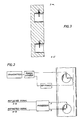
- a cylindrical cavity antenna (typically pad supported and surrounded by a metal face while the cavity is filled with space or other dielectric) is shown in Fig. 2 and has two probes oriented orthogonal to each other. Two identical signals differing in phase by 90° and having appropriate frequency are fed to these probes. At the aperture of this antenna which is in contact with the formation, a circularly polarized electromagnetic signal is radiated into the formation.
- the receiver is an identical cylindrical cavity with two probes orthogonal to each other. Assuming there is an interface, such as a mud cake, on the formation, a reflected wave will be returned to the receiver. Also arriving at the receiver is a refracted wave. If the original EM wave leaving the transmitter was right circularly polarized, the refracted wave will be right circularly polarized while the reflected wave will be left circularly polarized. If the signals from the two orthogonal probes are added together, the resultant signal is a measure of the refracted signal. If the signals from the orthogonal probes are subtracted, the resultant signal is a measure of the reflected signal. By processing the probe signals, one can determine both the reflected and refracted signals. Thus, Fugs. 2 and 3 show pad located separate antenna systems.
- the wave length is relatively long so that the spacing between the sonde 10 and the interface between the drilling fluid and formation is so close that there is no penetration.
- the interface may be so far removed from the transmitter that the signal is simply absorbed and there is no return signal at all.
- the signal When operating in the gigahertz range, if the signal has to travel through mud that is just an inch or so in thickness prior to illuminating the interface, the signal simply may not get there depending on the absorption characteristics of the drilling fluid. In summary, that also can be separately distinguished based on the response at the receiver 36.
- the antenna is ideally potted: the potting material as noted above is a piezoelectric ceramic which completely surrounds the antenna.
- the physical wave length is changed by the increase of the dielectric constant.
- the ceramic material where the dielectric constant is several hundred, indeed about 1300 for the PZT4 material mentioned above. This helps in reducing the size of the antenna. This helps in providing an antenna that will fit within the sonde 10.
- the mud is not very transparent; at other frequencies, the radiation may well penetrate the interface between the mud and the mud cake, the interface between the mud cake and the formation 30 and pass all the way through the invaded region of the formation 30. This typically can be obtained when operating at low frequencies. In any case, such adjustments in antenna frequency either in a potted environment (a high dielectric constant), or operating in space enables operating at preferred frequencies ranging from 10 Khz for certain tools on up to the gigahertz range for other types of tools.
- the present disclosure sets forth an antenna system involving transmission from an antenna of circular polarization signals at a selected frequency.
- the present disclosure has discussed operations at the gigahertz range all the way down to about 20 Khz.
- the response can be sorted out, namely the signals which are returned directly as a result of reflection and separately as refracted waves can be sorted out; this helps define the received constituents of the signal so that reflected-refracted signal interferences can be overcome and more accurate and useful data can be obtained. While the foregoing is directed to the preferred embodiment, the scope is determined by the claims which follow.
Landscapes
- Physics & Mathematics (AREA)
- Life Sciences & Earth Sciences (AREA)
- Electromagnetism (AREA)
- Engineering & Computer Science (AREA)
- Environmental & Geological Engineering (AREA)
- Geology (AREA)
- Remote Sensing (AREA)
- General Life Sciences & Earth Sciences (AREA)
- General Physics & Mathematics (AREA)
- Geophysics (AREA)
- Geophysics And Detection Of Objects (AREA)
Applications Claiming Priority (2)
| Application Number | Priority Date | Filing Date | Title |
|---|---|---|---|
| US463204 | 1990-01-10 | ||
| US07/463,204 US5066916A (en) | 1990-01-10 | 1990-01-10 | Technique for separating electromagnetic refracted signals from reflected signals in down hole electromagnetic tools |
Publications (2)
| Publication Number | Publication Date |
|---|---|
| EP0437364A2 true EP0437364A2 (fr) | 1991-07-17 |
| EP0437364A3 EP0437364A3 (en) | 1992-09-23 |
Family
ID=23839265
Family Applications (1)
| Application Number | Title | Priority Date | Filing Date |
|---|---|---|---|
| EP19910300175 Withdrawn EP0437364A3 (en) | 1990-01-10 | 1991-01-10 | Technique for separating electromagnetic refracted signals from reflected signals in down hole electromagnetic tools |
Country Status (3)
| Country | Link |
|---|---|
| US (1) | US5066916A (fr) |
| EP (1) | EP0437364A3 (fr) |
| CA (1) | CA2033819A1 (fr) |
Cited By (2)
| Publication number | Priority date | Publication date | Assignee | Title |
|---|---|---|---|---|
| EP0516525A1 (fr) * | 1991-05-28 | 1992-12-02 | Schlumberger Limited | Antenne à fente avec deux éléments non parallèles |
| EP0560651A3 (en) * | 1992-03-09 | 1994-08-17 | Schlumberger Ltd | Electromagnetic logging method and apparatus |
Families Citing this family (22)
| Publication number | Priority date | Publication date | Assignee | Title |
|---|---|---|---|---|
| FR2656111B1 (fr) * | 1989-12-19 | 1992-08-28 | Geophysique Cie Gle | Procede et dispositif d'acquisition de donnees sismiques de puits selon deux directions opposees. |
| US5345179A (en) * | 1992-03-09 | 1994-09-06 | Schlumberger Technology Corporation | Logging earth formations with electromagnetic energy to determine conductivity and permittivity |
| US5434507A (en) * | 1992-05-27 | 1995-07-18 | Schlumberger Technology Corporation | Method and apparatus for electromagnetic logging with two dimensional antenna array |
| GB9818875D0 (en) | 1998-08-28 | 1998-10-21 | Norske Stats Oljeselskap | Method and apparatus for determining the nature of subterranean reservoirs |
| GB0002422D0 (en) * | 2000-02-02 | 2000-03-22 | Norske Stats Oljeselskap | Method and apparatus for determining the nature of subterranean reservoirs |
| CN1246706C (zh) * | 2000-08-14 | 2006-03-22 | 电磁地形服务公司 | 确定地下储层性质的方法和设备 |
| GB2382875B (en) * | 2001-12-07 | 2004-03-03 | Univ Southampton | Electromagnetic surveying for hydrocarbon reservoirs |
| GB2385923B (en) * | 2002-05-24 | 2004-07-28 | Statoil Asa | System and method for electromagnetic wavefield resolution |
| GB2399640B (en) | 2003-03-17 | 2007-02-21 | Statoil Asa | Method and apparatus for determining the nature of submarine reservoirs |
| GB2409900B (en) | 2004-01-09 | 2006-05-24 | Statoil Asa | Processing seismic data representing a physical system |
| GB2434868B (en) | 2006-02-06 | 2010-05-12 | Statoil Asa | Method of conducting a seismic survey |
| GB2435693A (en) | 2006-02-09 | 2007-09-05 | Electromagnetic Geoservices As | Seabed electromagnetic surveying |
| GB2439378B (en) | 2006-06-09 | 2011-03-16 | Electromagnetic Geoservices As | Instrument for measuring electromagnetic signals |
| CN101529276B (zh) | 2006-09-08 | 2013-03-20 | 雪佛龙美国公司 | 用于监视钻井的遥测装置和方法 |
| GB2442749B (en) | 2006-10-12 | 2010-05-19 | Electromagnetic Geoservices As | Positioning system |
| GB2445582A (en) | 2007-01-09 | 2008-07-16 | Statoil Asa | Method for analysing data from an electromagnetic survey |
| US9547104B2 (en) * | 2007-09-04 | 2017-01-17 | Chevron U.S.A. Inc. | Downhole sensor interrogation employing coaxial cable |
| US10488286B2 (en) * | 2009-11-30 | 2019-11-26 | Chevron U.S.A. Inc. | System and method for measurement incorporating a crystal oscillator |
| US9063244B2 (en) * | 2012-03-19 | 2015-06-23 | Baker Hughes Incorporated | Induction logging signals using complex waveforms and directional guidance antenna systems |
| US9057799B2 (en) | 2012-03-19 | 2015-06-16 | Baker Hughes Incorporated | Induction logging signals and directional guidance antenna systems |
| US11391859B2 (en) | 2018-06-29 | 2022-07-19 | Halliburton Energy Services, Inc. | Determining formation properties in a geological formation using an inversion process on a modified response matrix associated with a downhole tool |
| CN115407410B (zh) * | 2022-10-27 | 2023-01-31 | 山东省鲁南地质工程勘察院(山东省地质矿产勘查开发局第二地质大队) | 一种基于无线电波反射的插入式矿产勘查装置 |
Family Cites Families (7)
| Publication number | Priority date | Publication date | Assignee | Title |
|---|---|---|---|---|
| US3582766A (en) * | 1969-11-13 | 1971-06-01 | Keigo Iizuka | Passively controlled duplexer-coupler applied to a helical antenna for use in a borehole penetrating an earth formation |
| US3944910A (en) * | 1973-08-23 | 1976-03-16 | Schlumberger Technology Corporation | Method and apparatus utilizing microwave electromagnetic energy for investigating earth formations |
| FR2283451A1 (fr) * | 1974-06-14 | 1976-03-26 | Rech Geolog Miniere | Methode et appareil de reconnaissance geophysique dans les forages par ondes tres basses frequences |
| US4383220A (en) * | 1979-05-07 | 1983-05-10 | Mobil Oil Corporation | Microwave electromagnetic borehole dipmeter |
| US4600887A (en) * | 1984-04-18 | 1986-07-15 | Mobil Oil Corporation | Microwave electromagnetic borehole dipmeter |
| GB8426245D0 (en) * | 1984-10-17 | 1984-11-21 | British Gas Corp | Microwave reflection survey equipment |
| GB8607705D0 (en) * | 1986-03-27 | 1986-04-30 | British Gas Corp | Signal processing |
-
1990
- 1990-01-10 US US07/463,204 patent/US5066916A/en not_active Expired - Fee Related
-
1991
- 1991-01-09 CA CA002033819A patent/CA2033819A1/fr not_active Abandoned
- 1991-01-10 EP EP19910300175 patent/EP0437364A3/en not_active Withdrawn
Cited By (2)
| Publication number | Priority date | Publication date | Assignee | Title |
|---|---|---|---|---|
| EP0516525A1 (fr) * | 1991-05-28 | 1992-12-02 | Schlumberger Limited | Antenne à fente avec deux éléments non parallèles |
| EP0560651A3 (en) * | 1992-03-09 | 1994-08-17 | Schlumberger Ltd | Electromagnetic logging method and apparatus |
Also Published As
| Publication number | Publication date |
|---|---|
| CA2033819A1 (fr) | 1991-07-11 |
| EP0437364A3 (en) | 1992-09-23 |
| US5066916A (en) | 1991-11-19 |
Similar Documents
| Publication | Publication Date | Title |
|---|---|---|
| US5066916A (en) | Technique for separating electromagnetic refracted signals from reflected signals in down hole electromagnetic tools | |
| US5530359A (en) | Borehole logging tools and methods using reflected electromagnetic signals | |
| US5475309A (en) | Sensor in bit for measuring formation properties while drilling including a drilling fluid ejection nozzle for ejecting a uniform layer of fluid over the sensor | |
| US9599741B2 (en) | Antenna of an electromagnetic probe for investigating geological formations | |
| US8664958B2 (en) | Antenna of an electromagnetic probe for investigating geological formations | |
| US4319191A (en) | Dielectric well logging with radially oriented coils | |
| US6788066B2 (en) | Method and apparatus for measuring resistivity and dielectric in a well core in a measurement while drilling tool | |
| US6191586B1 (en) | Method and apparatus for azimuthal electromagnetic well logging using shielded antennas | |
| US4814768A (en) | Downhole pulse radar | |
| US8680865B2 (en) | Single well reservoir imaging apparatus and methods | |
| CA2663477C (fr) | Antenne pour recherche de formations geologiques pour sonde electromagnetique et ses applications | |
| US5552786A (en) | Method and apparatus for logging underground formations using radar | |
| US4451789A (en) | Logging tool and method for measuring resistivity of different radial zones at a common depth of measurement | |
| EP2110688A1 (fr) | Appareil et procédé de diagraphie électromagnétique | |
| CN104737036B (zh) | 增强材料的调查 | |
| US3412815A (en) | Electromagnetic radiation method for guiding the drilling of oil wells after the borehole has entered a massive earth formation of chemically deposited material, by a mistake, accident, or the like | |
| Chen et al. | A modeling study of borehole radar for oilfield applications | |
| Nickel et al. | Exploring the interior of salt domes from boreholes | |
| GB2156527A (en) | Aperture antenna system for measurement of formation parameters | |
| US3412321A (en) | Oil-water contact location with frequency modulated electromagnetic energy | |
| CA2397916C (fr) | Systeme de mesure de la resistivite et de la constante dielectrique d'une carotte de sondage, systeme de mesure pour la mesure en cours de forage et laboratoire | |
| US3211252A (en) | Method and apparatus using seismic energy for detecting discontinuities | |
| US20250223903A1 (en) | Correlated wave-particle application for downhole measurements | |
| Kaveh et al. | Optimum Radar Signal for Production Zone Monitoring of the Oil Well |
Legal Events
| Date | Code | Title | Description |
|---|---|---|---|
| PUAI | Public reference made under article 153(3) epc to a published international application that has entered the european phase |
Free format text: ORIGINAL CODE: 0009012 |
|
| AK | Designated contracting states |
Kind code of ref document: A2 Designated state(s): DE DK FR GB NL |
|
| PUAL | Search report despatched |
Free format text: ORIGINAL CODE: 0009013 |
|
| AK | Designated contracting states |
Kind code of ref document: A3 Designated state(s): DE DK FR GB NL |
|
| 17P | Request for examination filed |
Effective date: 19921208 |
|
| STAA | Information on the status of an ep patent application or granted ep patent |
Free format text: STATUS: THE APPLICATION HAS BEEN WITHDRAWN |
|
| 18W | Application withdrawn |
Withdrawal date: 19930319 |