EP0437370B1 - Anschlussvorrichtung mit Kabelleitwegen - Google Patents
Anschlussvorrichtung mit Kabelleitwegen Download PDFInfo
- Publication number
- EP0437370B1 EP0437370B1 EP91300184A EP91300184A EP0437370B1 EP 0437370 B1 EP0437370 B1 EP 0437370B1 EP 91300184 A EP91300184 A EP 91300184A EP 91300184 A EP91300184 A EP 91300184A EP 0437370 B1 EP0437370 B1 EP 0437370B1
- Authority
- EP
- European Patent Office
- Prior art keywords
- terminal device
- cable
- coupling member
- slot
- cabinet
- Prior art date
- Legal status (The legal status is an assumption and is not a legal conclusion. Google has not performed a legal analysis and makes no representation as to the accuracy of the status listed.)
- Expired - Lifetime
Links
- 230000008878 coupling Effects 0.000 claims description 26
- 238000010168 coupling process Methods 0.000 claims description 26
- 238000005859 coupling reaction Methods 0.000 claims description 26
- 239000000463 material Substances 0.000 claims description 2
- 239000004033 plastic Substances 0.000 claims description 2
- 229920003023 plastic Polymers 0.000 claims description 2
- 238000010276 construction Methods 0.000 description 2
- 239000000446 fuel Substances 0.000 description 1
- 238000002347 injection Methods 0.000 description 1
- 239000007924 injection Substances 0.000 description 1
- 238000003780 insertion Methods 0.000 description 1
- 230000037431 insertion Effects 0.000 description 1
- 230000000007 visual effect Effects 0.000 description 1
Images
Classifications
-
- H—ELECTRICITY
- H05—ELECTRIC TECHNIQUES NOT OTHERWISE PROVIDED FOR
- H05K—PRINTED CIRCUITS; CASINGS OR CONSTRUCTIONAL DETAILS OF ELECTRIC APPARATUS; MANUFACTURE OF ASSEMBLAGES OF ELECTRICAL COMPONENTS
- H05K5/00—Casings, cabinets or drawers for electric apparatus
- H05K5/02—Details
- H05K5/0247—Electrical details of casings, e.g. terminals, passages for cables or wiring
-
- Y—GENERAL TAGGING OF NEW TECHNOLOGICAL DEVELOPMENTS; GENERAL TAGGING OF CROSS-SECTIONAL TECHNOLOGIES SPANNING OVER SEVERAL SECTIONS OF THE IPC; TECHNICAL SUBJECTS COVERED BY FORMER USPC CROSS-REFERENCE ART COLLECTIONS [XRACs] AND DIGESTS
- Y10—TECHNICAL SUBJECTS COVERED BY FORMER USPC
- Y10S—TECHNICAL SUBJECTS COVERED BY FORMER USPC CROSS-REFERENCE ART COLLECTIONS [XRACs] AND DIGESTS
- Y10S439/00—Electrical connectors
- Y10S439/942—Comblike retainer for conductor
Definitions
- This invention relates to terminal devices of the kind including: a cabinet having a first cabinet portion in which is mounted a first coupling member, and a second cabinet portion coupled to said first cabinet portion and adapted to be moved between opened and closed positions relative to said first cabinet portion; and a cable having a second coupling member adapted to couple with said first coupling member.
- connection cables which extend from connectors located at the backs of the terminals.
- the connectors which are exposed, tend to get damaged.
- the connectors tend to be pulled out of the machine, disrupting the operation of the terminal and other terminals attached to it.
- the connectors on a terminal may face a customer standing on one side of a counter while an operator operates the terminal while standing on the other side of the counter. The exposure of the customer to such connectors may present a hazard to the customer.
- US Patent No. US-A-4 680 425 discloses a cabinet containing a plurality of printed circuit boards having electrical connectors connected to one end.
- the electrical connectors are connected to respective cables which pass between a pivotably mounted, removable U-shaped bracket and a portion of the cabinet such that a pull on any one of cable causes the U-shaped bracket to pivot towards the cabinet, creating a clamping action of the cable, and acting as a cable strain relief device.
- the cables egress from the cabinet through a space defined by the bottom of a cabinet door and the top of a bottom rear portion of the cabinet.
- the U-shaped bracket is removed, and then reinserted in position with the cable located under the bracket. This arrangement in inconvienient in operation.
- the document DE-A-2 934 667 discloses an electrical connection box for telephones, accessory devices, etc, and consists of a universal socket, an intermediate part, which is constructed in accordance with the type of plug to be inserted therein, and a cover.
- the universal socket and intermediate part have aligned slots for receiving an electrical cable.
- the document GB-A-2 179 507 discloses a cable gripping device including fist and second parts which can be located within an aperture in the body part of a component such as a fuel injection nozzle.
- the outer part defines a passage leading to a channel defined between the parts by a groove in the outer part.
- the inner part has cable gripping elements which are aligned with the groove to grip a cable laid in the groove.
- a terminal device has the advantage of a simple and effective slot construction ensuring that a connection cable is properly routed through its retaining slot, to provide a neat visual appearance.
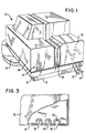
- Fig. 1 shows a business machine or terminal 10 in which a preferred embodiment or apparatus 12 (Fig. 2) of this invention may be used.
- the terminal 10 may be a table top terminal, like a teller operated entry terminal at a bank or an encoder, for example, although the apparatus 12 may be used in other terminals.
- the terminal 10 includes a cabinet designated generally as 14, with the cabinet 14 (shown closed in Fig. 1) having a base portion 16 including a perimeter portion 18.
- the cabinet 14 may be made of a conventional plastics material.
- the terminal 10 shown also has a document track 20 for moving documents (not shown) therethrough as the documents (like bank checks and deposit slips) are processed by the terminal 10. Because this aspect is not important to an understanding of this invention, it need not be discussed in any further detail.
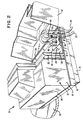
- Apparatus 12 (Fig. 2) provides the means for routing connection cables, like 22 and 24, out of the terminal 10 to enable the terminal 10 to be coupled to other units or terminals, like a host computer, for example, with these other units not being shown.
- the apparatus 12 is also referred to as a cable clip.
- the apparatus 12 (Fig. 2) includes a coupling member 26 which is mounted on a circuit board 28 which, in turn, is mounted substantially parallel to the base portion 16 of the terminal 10.
- the base portion 16 of the terminal 10 rests on a counter or table top 30 (shown only partially in Figs. 1 and 2).
- the top 26-1 of the coupling member 26, as viewed in Fig. 2 lies in an imaginary plane which is substantially parallel to the circuit board 28.
- the apparatus 12 also includes a cover 32 which is pivotally joined to the perimeter portion 18 of the base portion 16 by a conventional hinge 34, which is shown only as a line in Fig. 2, to enable the cover 32 to be pivotally moved between the closed position shown in Fig. 1 and the opened position shown in Fig. 2.
- Panel 36 represents the front of the cabinet 14, with the cables coming out one of the sides (like side 14-1) of the terminal 10 as shown.
- the perimeter portion 18 has a plurality of slots 38, 40, and 42 therein, as shown best in Fig. 3, in which the cables, like 22 and 24 are mounted.
- Each of the slots 38, 40, and 42 has a longitudinal axis (not shown) which is substantially perpendicular to the base portion 16 and the table top 30.
- Each of these slots, like 42 for example, is dimensioned to provide an entry throat 42-1 which has a width which is less than the diameter of the slot 42 itself.
- a cable, like 24 is inserted in the apparatus 12, the diameter of the cable 24 is compressed slightly by the entry throat 42-1 as the cable is pushed into the slot 42. This construction helps to retain the cable 24 in the associated slot 42 prior to moving the cover 32 to the closed position shown in Fig. 1.
- the cable 24 has a cooperative coupling member 44 on the end thereof to couple the cable 24 with the coupling member 26.
- the cable 22 has a cooperative coupling member 46 on the end thereof to couple the cable 22 with the coupling member 26.
- the coupling member 26 and the cooperative coupling members 46 and 48 may be conventional male-female coupling members, for example. After the cooperative coupling members 46 and 48 are inserted in the coupling member 26 and the cables 22 and 24 are pushed into the associated slots 40 and 42, as shown in Fig. 2, the cover 32 may be moved to the closed position shown in Fig. 1.
- the perimeter portion 18 has a recessed lip 18-1 which receives the cover 32 and provides some rigidity for the cover 32.
- Another advantage relates to having the coupling member 26 located inside the cabinet 14 as shown in Fig. 2. Notice that the cooperative coupling members, like 44 and 46, are pushed in a vertical direction (as viewed in Fig. 2) into the coupling member 26. This means that less board space is taken up on the circuit board 28 compared to prior art couplers which are end mounted. Having the connectors 44 and 46 mounted for vertical insertion makes it easier to do "trace routing" on the circuit board 28 when more than one communications coupler, like cooperative coupling member 44, is needed. The trace routes are considerably shortened compared to those necessary in rear mounted couplers.
- the terminal 10 presents a neat appearance as shown in Fig. 1. This is especially important for table top terminals where appearance and a small footprint are important. If the cables 22 and 24 are accidentally pulled while the cover 32 is closed, these cables would tend to raise the cover 32, thereby absorbing some of the energy of the pull to perhaps prevent the cooperative coupling members 44 and 46 from being disconnected. Also, with these coupling members 44 and 46 and 26 located on the inside of the cabinet 14, there is less of a chance for an electrostatic discharge to damage the circuit board 28.
Landscapes
- Engineering & Computer Science (AREA)
- Microelectronics & Electronic Packaging (AREA)
- Insertion, Bundling And Securing Of Wires For Electric Apparatuses (AREA)
- Connector Housings Or Holding Contact Members (AREA)
- Installation Of Indoor Wiring (AREA)
Claims (6)
- Anschlußvorrichtung aufweisend: ein Gehäuse (14) mit einem Unterteil (16), in dem ein erstes Anschlußelement (26) befestigt ist, und einem Abdeckteil (32), das mit dem Unterteil (16) verbunden und geeignet ist, bezüglich des Unterteils (16) zwischen einer geöffneten und einer geschlossenen Stellung bewegt zu werden; und ein Kabel (22) mit einem zweiten Anschlußelement (46), das zum Anschluß an das erste Anschlußelement (26) geeignet ist,
dadurch gekennzeichnet, daß
das Unterteil (16) einen sich erweiternden Umfangsabschnitt (18) aufweist und der Umfangsabschnitt (18) mit einer Durchgangsöffnung (40) versehen ist, wobei die Durchgangsöffnung (40) eine Längsachse aufweist, die senkrecht zur Grundfläche des Unterteils (16) verläuft, so daß sich, wenn das Abdeckteil (32) in der geschlossenen Stellung ist, das Kabel (22) von der Außenseite der Anschlußvorrichtung (10) weg auf der Längsachse der Durchgangsöffnung (40) und in das Innere der Anschlußvorrichtung (10) hinein erstreckt, wo es von dem Abdeckteil (32) umschlossen ist. - Anschlußvorrichtung nach Anspruch 1, dadurch gekennzeichnet, daß das erste Anschlußelement (26) eine Befestigungsfläche aufweist, die im wesentlichen parallel zur Grundfläche des Unterteils (16) ist.
- Anschlußvorrichtung nach Anspruch 2, dadurch gekennzeichnet, daß das Gehäuse (14) eine darin angeordnete Schaltungskarte (28) aufweist, wobei die Schaltungskarte (28) im wesentlichen parallel zur Grundfläche des Unterteils (16) angeordnet ist und daß das erste Anschlußelement (26) daran angeschlossen ist, und das erste Anschlußelement von dem Abdeckteil (32) abgedeckt ist, wenn das Abdeckteil (32) in die geschlossene Stellung bewegt wird.
- Anschlußvorrichtung nach einem der vorhergehenden Ansprüche, dadurch gekennzeichnet, daß die Durchgangsöffnung (40) einen Eingangsschlitz aufweist, der das Kabel (22) leicht zusammendrückt, wenn das Kabel in die Durchgangsöffnung (40) eingeführt wird und dadurch das Festhalten des Kabels (22) in der Durchgangsöffnung (40) unterstützt.
- Anschlußvorrichtung nach einem der Vorhergehenden Ansprüche, dadurch gekennzeichnet, daß der mit der Durchgangsöffnung (40) versehene Umfangsabschnitt (18) an einer Seite des Gehäuses (14) angeordnet ist.
- Anschlußvorrichtung nach einem der vorhergehenden Ansprüche, dadurch gekennzeichnet, daß zumindest der Umfangsabschnitt (18) aus Kunststoff besteht.
Applications Claiming Priority (2)
| Application Number | Priority Date | Filing Date | Title |
|---|---|---|---|
| US07/463,646 US5006960A (en) | 1990-01-11 | 1990-01-11 | Means for routing connection cables out of a table top terminal |
| US463646 | 1990-01-11 |
Publications (2)
| Publication Number | Publication Date |
|---|---|
| EP0437370A1 EP0437370A1 (de) | 1991-07-17 |
| EP0437370B1 true EP0437370B1 (de) | 1995-05-31 |
Family
ID=23840836
Family Applications (1)
| Application Number | Title | Priority Date | Filing Date |
|---|---|---|---|
| EP91300184A Expired - Lifetime EP0437370B1 (de) | 1990-01-11 | 1991-01-11 | Anschlussvorrichtung mit Kabelleitwegen |
Country Status (5)
| Country | Link |
|---|---|
| US (1) | US5006960A (de) |
| EP (1) | EP0437370B1 (de) |
| JP (1) | JP3021032B2 (de) |
| CA (1) | CA2029003A1 (de) |
| DE (1) | DE69110061T2 (de) |
Families Citing this family (29)
| Publication number | Priority date | Publication date | Assignee | Title |
|---|---|---|---|---|
| US5171155A (en) * | 1991-09-03 | 1992-12-15 | Humberto Mendoza | Safety lock for electrical appliance plugs |
| US5221813A (en) * | 1991-12-12 | 1993-06-22 | Ncr Corporation | Cable block for controlling cable routing in a terminal |
| JP2576858Y2 (ja) * | 1993-02-08 | 1998-07-16 | 矢崎総業株式会社 | コネクタ |
| JP2524471B2 (ja) * | 1993-07-22 | 1996-08-14 | 日本電気株式会社 | Emiガスケット |
| GB9317837D0 (en) * | 1993-08-27 | 1993-10-13 | Rose Walter Gmbh & Co Kg | A cable connector |
| DE9315970U1 (de) * | 1993-10-20 | 1993-12-02 | Mannesmann Kienzle Gmbh, 78052 Villingen-Schwenningen | Anordnung zum Verschließen einer Öffnung in einem Gehäuse |
| DE9403210U1 (de) * | 1994-02-25 | 1994-07-21 | Siemens AG, 80333 München | Gehäuse, das aus einem Basisgehäuseteil und einer Gehäuseabdeckung gebildet ist |
| DE9413475U1 (de) * | 1994-08-20 | 1994-10-13 | Mannesmann Kienzle Gmbh, 78052 Villingen-Schwenningen | Fahrtschreiber mit Mitteln zur geräteseitigen Befestigung eines den Geberleitungen zugeordneten Schutzrohres |
| US5886302A (en) * | 1995-02-08 | 1999-03-23 | Measurement Specialties, Inc. | Electrical weighing scale |
| DE19601518B4 (de) † | 1996-01-17 | 2016-05-12 | Wabco Gmbh | Gehäuse für eine elektrische Baugruppe |
| US5713758A (en) * | 1996-04-15 | 1998-02-03 | Black & Decker Inc. | Cordlock retention |
| EP0828319A1 (de) * | 1996-08-09 | 1998-03-11 | Sumitomo Wiring Systems, Ltd. | Verschlusskappe für Verbinder |
| US5739469A (en) * | 1996-08-13 | 1998-04-14 | Sony Corporation | Wire harness for a cabinet |
| DE19642445C1 (de) * | 1996-10-15 | 1998-03-05 | Krone Ag | Anschlußelement |
| US5790372A (en) * | 1997-01-24 | 1998-08-04 | Dell Usa, L.P. | Computer power supply mounting apparatus and method |
| US6129598A (en) * | 1997-06-23 | 2000-10-10 | Delta Electronic, Inc. | Printed-circuit-board (PCB) in a power supply system includes integrated cable connection terminals |
| US6050840A (en) * | 1997-08-08 | 2000-04-18 | Coleman Cable Systems, Inc. | Electrical plug |
| US6019645A (en) * | 1997-12-23 | 2000-02-01 | Molex Incorporated | Electrical connector assembly with terminal position assurance device |
| AU5141099A (en) * | 1998-08-18 | 2000-03-14 | Wong, Carven Louise | Organizer for cables and accessories in a computer or audio-video system |
| US6179665B1 (en) * | 1998-08-27 | 2001-01-30 | Curtis Computer Products, Inc. | Multi-function outlet strip having cable organizing features |
| EP1026043B1 (de) | 1999-02-02 | 2005-04-20 | Lear Corporation | Kabelbaumschaumschutz der über die Kabel einrastet |
| JP2001326027A (ja) * | 2000-05-15 | 2001-11-22 | Nec Gumma Ltd | Usbコネクタの抜け止め装置 |
| US20040036386A1 (en) * | 2002-08-26 | 2004-02-26 | Olivera Argelio M. | Surgical console |
| SE526528C2 (sv) * | 2004-12-22 | 2005-10-04 | Dometic Sweden Ab | Apparatlåda för dator samt kåpa för montering vid en apparatlåda för en dator |
| DE202007003572U1 (de) * | 2007-03-09 | 2008-01-17 | Wincor Nixdorf International Gmbh | Drucker mit USB-Anschluss |
| FR2914510B1 (fr) * | 2007-03-30 | 2009-12-18 | Legrand France | Armoire pour appareils electriques, comportant un socle presentant une trappe de passage pour des cables |
| JP5033021B2 (ja) * | 2008-03-03 | 2012-09-26 | 株式会社バッファロー | 筐体 |
| JP6283990B2 (ja) * | 2013-10-11 | 2018-02-28 | ティアック株式会社 | ケーブル固定装置 |
| USD772299S1 (en) * | 2014-06-27 | 2016-11-22 | Denso Corporation | Automotive engine computer unit cover |
Family Cites Families (9)
| Publication number | Priority date | Publication date | Assignee | Title |
|---|---|---|---|---|
| US2544343A (en) * | 1950-02-11 | 1951-03-06 | Gen Electric | Connector block with strain relief |
| US3879571A (en) * | 1973-05-07 | 1975-04-22 | Samuel M Reed | Cable mount for speaker installation |
| US4367909A (en) * | 1979-04-11 | 1983-01-11 | Amp Incorporated | Ribbon cable connector |
| DE2934667A1 (de) * | 1979-08-28 | 1981-03-19 | Dr. Franz & Rutenbeck, 5885 Schalksmühle | Anschlussdose fuer fernsprechapparate, zusatzeinrichtungen usw. |
| US4342946A (en) * | 1980-05-05 | 1982-08-03 | Orion Industries, Inc. | Timed automatic headlight shut-off |
| US4680425A (en) * | 1985-06-19 | 1987-07-14 | Ncr Corporation | Cable strain relief device |
| GB8521171D0 (en) * | 1985-08-23 | 1985-10-02 | Lucas Ind Plc | Cable gripping device |
| US4679869A (en) * | 1986-02-18 | 1987-07-14 | Ncr Corporation | Cable connector holder |
| US4816619A (en) * | 1988-06-29 | 1989-03-28 | Ncr Corporation | Passive strain relief apparatus |
-
1990
- 1990-01-11 US US07/463,646 patent/US5006960A/en not_active Expired - Lifetime
- 1990-10-31 CA CA002029003A patent/CA2029003A1/en not_active Abandoned
- 1990-11-30 JP JP2330917A patent/JP3021032B2/ja not_active Expired - Lifetime
-
1991
- 1991-01-11 DE DE69110061T patent/DE69110061T2/de not_active Expired - Fee Related
- 1991-01-11 EP EP91300184A patent/EP0437370B1/de not_active Expired - Lifetime
Also Published As
| Publication number | Publication date |
|---|---|
| JPH03216716A (ja) | 1991-09-24 |
| US5006960A (en) | 1991-04-09 |
| JP3021032B2 (ja) | 2000-03-15 |
| EP0437370A1 (de) | 1991-07-17 |
| CA2029003A1 (en) | 1991-07-12 |
| DE69110061T2 (de) | 1996-02-22 |
| DE69110061D1 (de) | 1995-07-06 |
Similar Documents
| Publication | Publication Date | Title |
|---|---|---|
| US5006960A (en) | Means for routing connection cables out of a table top terminal | |
| US5367598A (en) | Interface chassis for fiber optic transport system | |
| US5761368A (en) | Storage spool device for optical fibers | |
| US5538442A (en) | Communication card | |
| US5664955A (en) | Protective hood | |
| CA1189606A (en) | Electronic signal processing apparatus | |
| EP1148598B9 (de) | Adaptergehäuse für elektrische Steckverbinder | |
| EP0254889A2 (de) | Tragbares Elektronikgerät | |
| US7170749B2 (en) | Electrical apparatus and connector holder for electrical apparatus | |
| EP0917745B1 (de) | Abgeschirmtes, hohe dichtung verbindungspanel | |
| US5892662A (en) | "Open" card rack enclosures | |
| US5637001A (en) | PCMCIA connection device | |
| US6036529A (en) | Connector assembly with cable guide | |
| GB2338352A (en) | Video data connector assembly | |
| US6287133B1 (en) | Dustproof cover | |
| US5221813A (en) | Cable block for controlling cable routing in a terminal | |
| US5265186A (en) | Optical fiber distribution apparatus | |
| US5506927A (en) | Framework for housing optical equipment having optical fiber cable | |
| US6876809B1 (en) | Release mechanism for disconnecting internal fiber from an optical module | |
| US5222908A (en) | Bridge assembly | |
| FR2743977B1 (fr) | Tiroir pour cartes electroniques a embrochement et debrochage automatiques et tiroir et son coffre | |
| US6510056B1 (en) | Hinged removable connector module | |
| US5800198A (en) | Connector assembly | |
| KR100370614B1 (ko) | 콘센트가 설치된 전선 정리함 | |
| US5632641A (en) | Electrical connector |
Legal Events
| Date | Code | Title | Description |
|---|---|---|---|
| PUAI | Public reference made under article 153(3) epc to a published international application that has entered the european phase |
Free format text: ORIGINAL CODE: 0009012 |
|
| AK | Designated contracting states |
Kind code of ref document: A1 Designated state(s): DE FR GB |
|
| 17P | Request for examination filed |
Effective date: 19920109 |
|
| 17Q | First examination report despatched |
Effective date: 19931222 |
|
| RAP1 | Party data changed (applicant data changed or rights of an application transferred) |
Owner name: NCR INTERNATIONAL INC. |
|
| RAP1 | Party data changed (applicant data changed or rights of an application transferred) |
Owner name: AT&T GLOBAL INFORMATION SOLUTIONS INTERNATIONAL IN |
|
| GRAA | (expected) grant |
Free format text: ORIGINAL CODE: 0009210 |
|
| AK | Designated contracting states |
Kind code of ref document: B1 Designated state(s): DE FR GB |
|
| REF | Corresponds to: |
Ref document number: 69110061 Country of ref document: DE Date of ref document: 19950706 |
|
| ET | Fr: translation filed | ||
| PLBE | No opposition filed within time limit |
Free format text: ORIGINAL CODE: 0009261 |
|
| STAA | Information on the status of an ep patent application or granted ep patent |
Free format text: STATUS: NO OPPOSITION FILED WITHIN TIME LIMIT |
|
| 26N | No opposition filed | ||
| REG | Reference to a national code |
Ref country code: FR Ref legal event code: CD |
|
| REG | Reference to a national code |
Ref country code: GB Ref legal event code: IF02 |
|
| REG | Reference to a national code |
Ref country code: GB Ref legal event code: 746 Effective date: 20030114 |
|
| REG | Reference to a national code |
Ref country code: FR Ref legal event code: D6 |
|
| PGFP | Annual fee paid to national office [announced via postgrant information from national office to epo] |
Ref country code: FR Payment date: 20050131 Year of fee payment: 15 |
|
| PGFP | Annual fee paid to national office [announced via postgrant information from national office to epo] |
Ref country code: GB Payment date: 20060117 Year of fee payment: 16 |
|
| PGFP | Annual fee paid to national office [announced via postgrant information from national office to epo] |
Ref country code: DE Payment date: 20060217 Year of fee payment: 16 |
|
| PG25 | Lapsed in a contracting state [announced via postgrant information from national office to epo] |
Ref country code: DE Free format text: LAPSE BECAUSE OF NON-PAYMENT OF DUE FEES Effective date: 20070801 |
|
| GBPC | Gb: european patent ceased through non-payment of renewal fee |
Effective date: 20070111 |
|
| REG | Reference to a national code |
Ref country code: FR Ref legal event code: ST Effective date: 20070930 |
|
| PG25 | Lapsed in a contracting state [announced via postgrant information from national office to epo] |
Ref country code: GB Free format text: LAPSE BECAUSE OF NON-PAYMENT OF DUE FEES Effective date: 20070111 |
|
| PG25 | Lapsed in a contracting state [announced via postgrant information from national office to epo] |
Ref country code: FR Free format text: LAPSE BECAUSE OF NON-PAYMENT OF DUE FEES Effective date: 20070131 |
|
| PG25 | Lapsed in a contracting state [announced via postgrant information from national office to epo] |
Ref country code: FR Free format text: LAPSE BECAUSE OF NON-PAYMENT OF DUE FEES Effective date: 20060131 |