EP0437375B1 - Méthode et dispositif pour fabriquer un mur en blocs de verre - Google Patents
Méthode et dispositif pour fabriquer un mur en blocs de verre Download PDFInfo
- Publication number
- EP0437375B1 EP0437375B1 EP91300205A EP91300205A EP0437375B1 EP 0437375 B1 EP0437375 B1 EP 0437375B1 EP 91300205 A EP91300205 A EP 91300205A EP 91300205 A EP91300205 A EP 91300205A EP 0437375 B1 EP0437375 B1 EP 0437375B1
- Authority
- EP
- European Patent Office
- Prior art keywords
- glass
- blocks
- glass block
- glass blocks
- spacer
- Prior art date
- Legal status (The legal status is an assumption and is not a legal conclusion. Google has not performed a legal analysis and makes no representation as to the accuracy of the status listed.)
- Expired - Lifetime
Links
- 239000011521 glass Substances 0.000 title claims abstract description 160
- 238000000034 method Methods 0.000 title description 5
- 125000006850 spacer group Chemical group 0.000 claims abstract description 89
- 239000000463 material Substances 0.000 claims abstract description 16
- 239000000945 filler Substances 0.000 claims abstract description 5
- 239000011324 bead Substances 0.000 claims description 11
- 238000004519 manufacturing process Methods 0.000 claims description 3
- 229920002457 flexible plastic Polymers 0.000 claims description 2
- 230000004927 fusion Effects 0.000 claims description 2
- 229920001296 polysiloxane Polymers 0.000 description 7
- 229920000915 polyvinyl chloride Polymers 0.000 description 6
- 239000004800 polyvinyl chloride Substances 0.000 description 6
- 229920003023 plastic Polymers 0.000 description 3
- 239000004033 plastic Substances 0.000 description 3
- 230000013011 mating Effects 0.000 description 2
- 239000004570 mortar (masonry) Substances 0.000 description 2
- 229920002972 Acrylic fiber Polymers 0.000 description 1
- 239000004677 Nylon Substances 0.000 description 1
- LNUFLCYMSVYYNW-ZPJMAFJPSA-N [(2r,3r,4s,5r,6r)-2-[(2r,3r,4s,5r,6r)-6-[(2r,3r,4s,5r,6r)-6-[(2r,3r,4s,5r,6r)-6-[[(3s,5s,8r,9s,10s,13r,14s,17r)-10,13-dimethyl-17-[(2r)-6-methylheptan-2-yl]-2,3,4,5,6,7,8,9,11,12,14,15,16,17-tetradecahydro-1h-cyclopenta[a]phenanthren-3-yl]oxy]-4,5-disulfo Chemical compound O([C@@H]1[C@@H](COS(O)(=O)=O)O[C@@H]([C@@H]([C@H]1OS(O)(=O)=O)OS(O)(=O)=O)O[C@@H]1[C@@H](COS(O)(=O)=O)O[C@@H]([C@@H]([C@H]1OS(O)(=O)=O)OS(O)(=O)=O)O[C@@H]1[C@@H](COS(O)(=O)=O)O[C@H]([C@@H]([C@H]1OS(O)(=O)=O)OS(O)(=O)=O)O[C@@H]1C[C@@H]2CC[C@H]3[C@@H]4CC[C@@H]([C@]4(CC[C@@H]3[C@@]2(C)CC1)C)[C@H](C)CCCC(C)C)[C@H]1O[C@H](COS(O)(=O)=O)[C@@H](OS(O)(=O)=O)[C@H](OS(O)(=O)=O)[C@H]1OS(O)(=O)=O LNUFLCYMSVYYNW-ZPJMAFJPSA-N 0.000 description 1
- 239000011449 brick Substances 0.000 description 1
- 239000000919 ceramic Substances 0.000 description 1
- 230000006835 compression Effects 0.000 description 1
- 238000007906 compression Methods 0.000 description 1
- 238000007796 conventional method Methods 0.000 description 1
- 238000009434 installation Methods 0.000 description 1
- 238000012986 modification Methods 0.000 description 1
- 230000004048 modification Effects 0.000 description 1
- 239000006060 molten glass Substances 0.000 description 1
- 238000000465 moulding Methods 0.000 description 1
- 229920001778 nylon Polymers 0.000 description 1
- 230000002093 peripheral effect Effects 0.000 description 1
- 239000007787 solid Substances 0.000 description 1
- 238000009966 trimming Methods 0.000 description 1
- 239000002023 wood Substances 0.000 description 1
Images
Classifications
-
- E—FIXED CONSTRUCTIONS
- E04—BUILDING
- E04C—STRUCTURAL ELEMENTS; BUILDING MATERIALS
- E04C1/00—Building elements of block or other shape for the construction of parts of buildings
- E04C1/42—Building elements of block or other shape for the construction of parts of buildings of glass or other transparent material
-
- E—FIXED CONSTRUCTIONS
- E04—BUILDING
- E04B—GENERAL BUILDING CONSTRUCTIONS; WALLS, e.g. PARTITIONS; ROOFS; FLOORS; CEILINGS; INSULATION OR OTHER PROTECTION OF BUILDINGS
- E04B2/00—Walls, e.g. partitions, for buildings; Wall construction with regard to insulation; Connections specially adapted to walls
- E04B2/02—Walls, e.g. partitions, for buildings; Wall construction with regard to insulation; Connections specially adapted to walls built-up from layers of building elements
- E04B2/04—Walls having neither cavities between, nor in, the solid elements
- E04B2/06—Walls having neither cavities between, nor in, the solid elements using elements having specially-designed means for stabilising the position
-
- E—FIXED CONSTRUCTIONS
- E04—BUILDING
- E04B—GENERAL BUILDING CONSTRUCTIONS; WALLS, e.g. PARTITIONS; ROOFS; FLOORS; CEILINGS; INSULATION OR OTHER PROTECTION OF BUILDINGS
- E04B2/00—Walls, e.g. partitions, for buildings; Wall construction with regard to insulation; Connections specially adapted to walls
- E04B2/02—Walls, e.g. partitions, for buildings; Wall construction with regard to insulation; Connections specially adapted to walls built-up from layers of building elements
- E04B2002/0256—Special features of building elements
- E04B2002/028—Spacers between building elements
- E04B2002/0282—Separate spacers
Definitions
- This invention relates to a method and apparatus for erecting a wall and more particularly to a method and apparatus for erecting a glass block wall within a frame member with spacer members positioned between the end walls of adjacent glass blocks.
- Glass block walls have been erected in the past.
- the conventional method for erecting such walls include the use of mortar between the horizontal and vertical end walls much in the same manner as a conventional brick wall. Separate spacers have also been positioned between the horizontal end walls of the glass blocks.
- the end walls of the blocks have also been modified to provide mating surfaces with dove-tall type mortar receiving portions, other types of recessed portions and upwardly extending rail-like shoulder portions.
- United States Patent 4,058,943 discloses a glass block panel with a plurality of rigid interlocked spacers which form a grid-like structure surrounding the glass blocks.
- United States Patent 2,318,362 discloses a wall structure where the glass blocks have rib-like grooves in the end walls that are positioned on separator strips so that the wall structure may be disassembled without damaging the glass blocks.
- United States Patent 4, 648, 226 discloses a glass block with a modified configuration of the end walls.
- the modified glass blocks are arranged to be positioned in a frame having a mating configuration to maintain the glass blocks in a wall structure.
- German Patent Publication DE 3304971 Al discloses a method of fabricating a glass block wall using glass blocks of generally rectangular configuration and including a spacer member between the glass blocks in assembly, the ends of which have rib portions for supporting the glass blocks.
- German Patent Publication DE 3328791 Al which is related to the above identified German Patent Publication, discloses a similar structure.
- the joint appears to be a spacer having an elliptical configuration in section with inclined side walls that permit limited compression of the spacers.
- the spacers are wedged between the glass blocks during erection of the wall.
- a glass block wall comprising a plurality of glass blocks mounted in a frame, said glass blocks each formed from a pair of hollow glass block halves with rectangular edge portions fused to each other and forming a raised continuous bead therebetween, said glass blocks having a generally rectangular configuration with end walls and side walls forming edge portions therebetween, said glass blocks having a preselected thickness between said side walls, said raised continuous bead formed in said vertical and horizontal end walls intermediate said edge portions, said glass blocks being positioned in abutting relationship with each other with spacer members positioned between adjacent end walls of said glass blocks, said spacer member having a body portion with longitudinal side edge portions and a transverse dimension substantially equal to the distance between the block edge portions of opposite side walls and smaller than said preselected thickness of said glass block in order to provide a channel shaped recess portion between adjacent block edge portions and the side edge portions, each said side edge portion forming a rib projecting above and below said body portion, the rib having an upper shoulder portion and a lower
- a spacer member for positioning between adjacent blocks of a glass block wall, each glass block having a beaded portion formed between two fused halves thereof, the spacer member comprising, an elongated body portion formed from a flexible plastics material having sufficient strength to resist deformation under load, said body portion having a top surface, a bottom surface and side edge portions forming a rib projecting above and below said body portion, the rib having an upper shoulder portion and a lower shoulder portion provided with flat surfaces for abutting outer edge portions of adjacent blocks, the spacer member having a width corresponding substantially to the distance between the opposite outer edge portions of the block, characterised in that said top surface of the body portion has a pair of spaced parallel longitudinal ribs intermediate the respective ends of the spacer member and forming a recess portion therebetween for receiving the bead of a glass block, formed by fusion of glass block halves to form the glass block, mounted on the spacer member, said bottom surface having a second pair of spaced parallel longitudinal rib
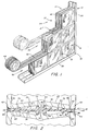
- a glass block wall generally designated by the numeral 10 that includes a frame member 12, a plurality of glass blocks 14 with spacer members 16 positioned therebetween and a silicone caulking material 18 positioned in the joints between the glass blocks 14.
- the frame member 12 is preferably fabricated from a rigid polyvinyl chloride material although the frame member 12 may be fabricated from any other suitable material which provides a rigid frame for the glass blocks.
- the frame member 12 has a body portion 20 and a pair of flanged end or edge portions 22 and 24.
- the flanged portions 22 and 24 are so dimensioned that they receive a glass block therebetween and are inwardly bent relative to the body portion 20 so that the blocks will snap into position within the frame 12 and be frictionally engaged therein.
- the glass block abuts the front edge of the body portion 20.
- the frame 12 is made from a rigid polyvinyl chloride that will yield sufficiently to permit the glass blocks 14 to be snapped into place within the frame member and has sufficient rigidity for the flanges 22 and 24 to frictionally retain the glass block members therein and provide rigidity for the glass block wall 10.
- the frame body member 20 has a plurality of apertures 26 therein arranged to receive wood screws or other fastening means to fasten the frame member 12 to a rigid adjoining structure.
- the frame member 12 fabricated from the channel-shaped plastic members has a vertical member 28 and a horizontal member 30 suitably joined to each other to form a corner 32. It should be understood that the frame member may also have another horizontal top member and another vertical member to form a generally rectangular frame. It should be understood, however, that the glass block wall may be fabricated with a portion of a frame that may be positioned in an appropriate opening within a structure.
- the glass blocks 14 are conventional glass blocks having a generally rectangular configuration which are formed by fusing a pair of glass block halves to each other to form the hollow glass block.
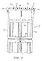
- the glass blocks have a configuration as illustrated in Figures 2 and 3 with a pair of side walls or faces 32 and 34 with four peripheral vertical and horizontal end walls 36 which are joined to the side walls or faces 32 and 34.
- the glass block end walls 36 have the same configuration, however, in certain types of blocks which are rectangular with one dimension greater than the other, the area of the longer walls is greater than the area of the shorter vertical walls.
- the glass blocks are formed by a glass molding process where molten glass is poured into a mold and one-half of the block is formed in the mold. Thereafter two of the block halves are positioned with the free edges abutting each other and are subjected to heat to melt the glass along the edges and fuse the two block halves to each other to thus form a unitary, hollow glass block.
- the glass block end walls 36 have a raised portion or bead 38 which extends around the periphery of the block and is formed by the fused joint between the block halves. As illustrated in Figure 2, the walls 36 have an inclined portion 40 and a rounded edge portion 42 with the edge portion 42 extending slightly below the raised portion 38.
- the spacer member 16 positioned between the walls 38 of the glass blocks 14 is illustrated in detail in Figure 2.
- the spacer member 16 is preferably fabricated from a suitable plastic material such as a flexible polyvinyl chloride having a 65 durometer hardness and is preferably fabricated from a clear polyvinyl chloride material. It should be understood that other flexible materials having the desired rigidity to support the wall without substantial deformation may also be used.
- the spacer member 16 is fabricated in elongated lengths and may be stored in rolls 44 as illustrated in Figure 1. The configuration of the spacer member 16 as later discussed is formed by extruding the polyvinyl chloride through an appropriate die to provide the desired configuration.
- Segments 46 of the spacer 16 which are positioned along the glass block vertical walls 36 are cut to a preselected length from the extruded spacer member to have a dimension where the spacer 46 will be in substantial juxtaposition with and preferably abut the continuous horizontal spacer 48.
- the intersection of the vertical spacer 46 and the continuous horizontal spacer 48 is illustrated in Figure 1 along the first course of the glass blocks 14 in the glass block wall 10.
- the spacer 16 has a body portion 50 with a pair of intermediate rails 52 and 54 extending upwardly therefrom on opposite sides of the longitudinal axis of the spacer and a pair of downwardly extending rails 56 and 58 with the rails 52 and 54 being aligned with rails 56 and 58.
- a top channel or recess 60 is formed between the rails 52 and 54 and a bottom channel or recess 62 is formed between the rails 56 and 58.
- the spacer 16 is arranged to be positioned between the end walls 36 of adjacent glass blocks 14 with the raised portions 38 in the walls 36 extending downwardly into the respective channels 60 and 62.
- the channels 60 and 62 thus position the spacer member 16 relative to the glass block walls 36 by the glass block raised portions 38 extending into the respective channels and align the adjacent blocks relative to each other.
- the spacer 16 has longitudinal edge portions 66 and 68 which have a rail-like configuration in section with a pair of upper and lower longitudinally extending ribs 70, 72, 74 and 76 respectively.
- the ribs 70-76 are arranged to abut the inclined surface 40 of the glass block walls 36 to provide further stability to the glass blocks as they are positioned in the wall 10.
- the ribs 70-76 are arranged to provide additional stability to that provided by the enlarged edge portions 66 and 68 of the spacer 16.
- the edge portions 66 and 68 have upper shoulder portions 78 and 80 and lower shoulder portions 82 and 84.
- the shoulder portions 78-84 all have flat surfaces 86 which are arranged to abut the adjacent wall of the glass block so that the glass block rests on the flat surfaces 86 to support and stabilize the glass blocks 14 when positioned in the wall 10.
- the ribs 70-76 spaced inwardly from the shoulders 78-84 are arranged to provide additional stability to the glass blocks 14 and in certain types of installations the intermediate ribs 70-76 may be omitted where the shoulders 78-84 provide adequate stability for the glass blocks 14 in the wall 10.
- the vertical dimension between the flat surfaces 86 of shoulders 78 and 82 and 80 and 84 is preferably such that the spacing between the curved edges 42 of the glass block is approximately 1/8 ⁇ and the width of the space is such that a space is provided between the edges of the glass block and the edges 66 and 68 of the spacer is about 1/8 ⁇ .
- Such a spacing provides a space for the silicone caulking 18 which will cure and set and rigidify to further add rigidity to the glass block wall. Silicone caulking in large amounts does not rigidify throughout and thus does not provide a rigid filler material. With the dimensions of the space 88 provided between the glass block edges 42 and the spacer edges 66 and 68, the silicone caulking 18 will rigidify and provide additional stability to the glass block wall 10.
- the glass block wall 10 is erected as illustrated in the preferred embodiment.
- the frame 10 is secured to an adjacent rigid structure by means of screws or the like extending through the apertures 26 into the adjacent structure.
- the first course 90 of glass blocks 14 is positioned in the frame by wedging the glass blocks between the frame flanges 22 and 24.
- a segment of the spacer 16 referred to as the vertical spacer 46 is positioned between the vertical end walls 36 of the adjacent glass blocks so that the first course 90 includes the glass blocks 14 with the vertical spacers 46 therebetween.
- the end walls 36 of the glass blocks abut the vertical spacer 46 as previously described with the recessed portions 38 of each glass block extending into the adjacent channels 60 and 62 of the spacer 16 as illustrated in Figure 3.
- a roll 44 of spacer material is positioned in abutting relation with the upper horizontal end walls 36 of the glass blocks 14 and extend the length of the first course.
- the vertical spacers 46 are of such a length that they are in juxtaposition with the underside of the horizontal spacer 48.
- a second glass block is positioned in overlying relation with the second glass block in the first course and is moved into abutting relation with the vertical spacer 46 between the first and second glass block.
- This procedure is continued alternating glass blocks 14 and vertical spacers 46 until the second course 92 is completed.
- a horizontal spacer 48 is positioned on the upper surface of the second course of glass blocks by again unrolling the spacer from the spacer roll so that it extends along the entire length of the wall.
- the end of the continuous horizontal spacer 48 is formed by cutting the spacer from the roll 44 at the preselected length. It should be understood that the horizontal spacer 48 may be cut into any suitable lengths from the roll 44 before the wall is formed as long as the horizontal spacer extends along the length of a glass block.
- the second course 92 has the glass blocks 14 in abutting relation with the upper surface of the horizontal spacer 48 and vertical spacers 46 are positioned between the adjacent glass blocks.
- the third course 94 is installed in a similar manner as are the remaining courses in the glass block wall 10.
- the first course 90 preferably has both end blocks 13 positioned in a vertical frame member 28 and the top course has the glass blocks positioned in an upper horizontal frame (not shown) 30. It should be understood that a unitary rectangular wall structure may be formed or preassembled with the respective vertical and horizontal frames 28 and 30 secured in position and the preassembled wall transported to a location for assembly as either a separate wall or installed in an existing opening.
- a suitable silicone caulking compound 18 is applied in the opening 88 and may be trimmed by a suitable trimming tool to form a smooth surface which will rigidify and provide aesthetic appearance in addition to rigidifying the glass block wall.
Landscapes
- Architecture (AREA)
- Engineering & Computer Science (AREA)
- Civil Engineering (AREA)
- Structural Engineering (AREA)
- Physics & Mathematics (AREA)
- Electromagnetism (AREA)
- Securing Of Glass Panes Or The Like (AREA)
- Re-Forming, After-Treatment, Cutting And Transporting Of Glass Products (AREA)
- Manufacture, Treatment Of Glass Fibers (AREA)
- Glass Compositions (AREA)
- Conveying And Assembling Of Building Elements In Situ (AREA)
- Measurement Of Radiation (AREA)
- Finishing Walls (AREA)
- Load-Bearing And Curtain Walls (AREA)
Claims (8)
- Mur en verre constitué par une pluralité de blocs de verre (14) montés dans un cadre (12), lesdits bloc de verre (14), formés chacun par deux moitiés de blocs de verre creux ayant des parties de bords rectangulaires, fondues entre elles et formant un bourrelet continu (28) en surépaisseur entre elles, lesdits blocs de verre (14) ayant une forme généralement rectangulaire avec des parois d'extrémités (36) de forme rectangulaire et des parois latérales (32, 34) formant entre eux des parties de bords (42), lesdits blocs de verre (14) ayant une épaisseur, choisie d'avance, entre lesdites parois latérales (32, 34), ledit bourrelet continu en surépaisseur (38) formé dans lesdites parois d'extrémités verticales et horizontales (36) en une position intermédiaire entre lesdites parties de bords (42), lesdits blocs de verre (14) étant posés en relation de butée l'un contre l'autre en plaçant des éléments de cales (16) entre des parois d'extrémités adjacentes (36) desdits blocs de verre (14), ledit élément de cale (16) présentant une partie principale (50) avec des parties de bords latéraux longitudinaux (66, 68) et une dimension transversale sensiblement égale à la distance entre les parties de bords de blocs (42) des parois latérales opposées (32, 34) et inférieure à ladite épaisseur, choisie d'avance, desdits blocs de verre (14) afin de ménager une partie d'évidement en forme de canal (88) entre lesdites parties de bords de blocs (42) et les parties de bords latéraux (66, 68), chacune desdites parties de bords latéraux (66, 68) formant une nervure faisant saillie au-dessus et au-dessous de ladite partie principale, la nervure présentant une partie d'épaulement supérieure (78, 80) et une partie d'épaulement inférieure (82, 84) ayant des surfaces planes (86) qui butent contre les parties de bord (42), caractérisé en ce que ledit élément de cale (16) est doté de deux parties de nervures, intermédiaires, espacées (52, 54, 56, 58) formant une partie supérieure d'évidement (60) et une partie inférieure d'évidement (62) s'étendant sur la longueur dudit élément de cale (16) pour recevoir respectivement undit bourrelet en surépaisseur (38) des blocs de verre adjacents (14) de façon à aligner et à stabiliser des blocs de verre adjacents (14) du mur en blocs de verre.
- Mur en blocs de verre selon la revendication 1, dans lequel un matériau de remplissage (18) occupe lesdites parties d'évidement (88) pour fixer les blocs (14) les uns aux autres et auxdites parties de bords (66, 68) des éléments de cales (16)
- Mur en blocs de verre selon l'une quelconque des revendications précédentes, dans lequel lesdites parois latérales (36) des blocs de verre (14) ont des parties de surfaces inclinées (40), ledit élément de cale (16) ayant deux secondes nervures intermédiaires (70, 72, 74, 76) entre ladite partie longitudinale (60, 68) et lesdites premières parties de nervures intermédiaires (52, 54, 56, 58), lesdites secondes nervures intermédiaires (70, 72, 74, 76) étant en butée sur lesdites parties de surfaces inclinées (40) pour stabiliser davantage lesdits blocs de verre dans ledit mur (10).
- Mur de blocs de verre selon l'une quelconque des revendications précédentes, dans lequel les éléments de cales (16) placés entre lesdites parois verticales desdits blocs de verre (14) ont une dimension sensiblement égale à la hauteur desdits blocs de verre (14), et les éléments de cales placés entre lesdites parois horizontales desdits blocs de verre ont une dimension dépassant la longueur desdits blocs de verre (14) et s'étendant sur une pluralité de blocs de verre (14), lesdits éléments de cales (16) placés entre lesdites parois verticales (36) étant en juxtaposition avec lesdits éléments de cales (16) placés entre lesdites parois horizontales (36).
- Mur de blocs de verre selon la revendication 1, dans lequel l'élément de cadre (12) comprend deux éléments de cadre (28, 30) maintenus sous un certain angle entre eux, lesdits éléments de cadre (28, 30) ayant une partie principale (20) et une paire de parties de bords longitudinaux à brides, espacées (22, 24) l'une de l'autre qui en partent sous un certain angle et qui convergent l'une vers l'autre pour former avec la partie principale (20) une rainure ayant une dimension d'ouverture légèrement inférieure à l'épaisseur, choisie d'avance, desdits blocs (14) pour recevoir à l'intérieur les blocs (14) en prise de frottement, certains desdits blocs (14) étant agencés pour avoir desdites parois latérales (32, 34) en prise de frottement avec des parties de bords à bride (22, 24) de l'un desdits éléments de cadre (28) et les autres desdits blocs (14) étant disposés de façon à avoir lesdites parois latérales (32, 34) en prise de frottement avec l'autre élément de cadre (30) dudit cadre (12).
- Elément de cale à placer entre des blocs adjacents d'un mur en blocs de verre, chaque bloc de verre ayant une partie de bourrelet formée entre deux de ses moitiés fondues, l'élément de cale comprenant une partie principale allongée (50) constituée en une matière plastique souple ayant une robustesse suffisante pour résister aux déformations en charge, ladite partie principale (50) ayant une surface supérieure, une surface inférieure et des parties de bords latéraux (66, 68) formant une nervure qui fait saillie au-dessus et au-dessous de ladite partie principale, la nervure ayant une partie d'épaulement supérieur (78, 80) et une partie d'épaulement inférieur (82, 84) comportant des surfaces planes (86) pour venir en butée sur des parties de bords extérieurs (42) des blocs adjacents, l'élément de cale ayant une largeur qui correspond sensiblement à la distance entre les parties de bords extérieurs opposés (42) du bloc, caractérisé en ce que ladite surface supérieure de la partie principale (50) présente deux nervures longitudinales parallèles espacées (52, 54), placées entre les extrémités respectives de l'élément de cale formant, entre elles, une partie d'évidement (60) pour recevoir le bourrelet d'un bloc de verre, formé par la fusion de moitiés de bloc de verre, monté sur l'élément de cale, ladite surface inférieure ayant une seconde paire de nervures longitudinales parallèles, espacées (56, 58) alignées avec ladite première paire de nervures (52, 54) et formant une partie d'évidement (56, 52) pour recevoir ledit bourrelet du bloc de verre adjacent, afin d'aligner et de stabiliser ainsi des blocs de verre adjacents du mur en blocs de verre
- Procédé de fabrication d'un mur en blocs de verre consistant à : (a) poser un premier bloc de verre (14) dans un angle (31) d'un cadre (12) en prise de frottement avec des éléments (28, 30) de ce cadre, disposés en faisant un certain angle entre eux, (b) à constituter un premier rang de blocs de verre (14) le long d'un élément (28) de ce cadre, en prise de frottement avec lui, (c) à poser un élément de cale (16) selon la revendication 7 ou 8 entre des parois d'extrémités adjacentes des blocs de verre (14) le long dudit premier rang, chaque élément de cale (16) ayant une longueur sensiblement égale à la hauteur desdits blocs de verre (14), (d) à poser undit élément de cale (16) ayant une largeur inférieure à celle des blocs de verre (14) sur les parois supérieures desdits blocs de verre (16) entre lesdites parois d'extrémité des blocs (14), (e) à constituter un second rang de blocs de verre (14) le long de l'élément de cale (16) au-dessus du premier rang de manière à former des évidements (88) entre les bords en vis-à-vis des blocs de verre le long des rangs respectifs et les bords (66, 68) de l'élément de cale (16), le premier bloc de verre du second rang étant en prise de friction avec l'élément de cadre (28), (f) à poser un élément de cale (16) entre les parois d'extrémités adjacentes des blocs de verre (14) du second rang et à répétiter les opérations (d) à (f) pour former des rangs supplémentaires de blocs de verres (14) de chaque rang jusqu'à ce que le mur soit terminé.
- Procédé de fabrication d'un mur en blocs de verre selon la revendication 7, dans lequel un matériau de remplissage (18) est placé dans les évidements (88) pour stabiliser davantage le mur en blocs de verre (20).
Applications Claiming Priority (2)
| Application Number | Priority Date | Filing Date | Title |
|---|---|---|---|
| US07/463,386 US4986048A (en) | 1990-01-11 | 1990-01-11 | Method and apparatus for erecting a glass block wall |
| US463386 | 1990-01-11 |
Publications (2)
| Publication Number | Publication Date |
|---|---|
| EP0437375A1 EP0437375A1 (fr) | 1991-07-17 |
| EP0437375B1 true EP0437375B1 (fr) | 1994-06-29 |
Family
ID=23839904
Family Applications (1)
| Application Number | Title | Priority Date | Filing Date |
|---|---|---|---|
| EP91300205A Expired - Lifetime EP0437375B1 (fr) | 1990-01-11 | 1991-01-11 | Méthode et dispositif pour fabriquer un mur en blocs de verre |
Country Status (10)
| Country | Link |
|---|---|
| US (1) | US4986048A (fr) |
| EP (1) | EP0437375B1 (fr) |
| JP (1) | JPH04221154A (fr) |
| AT (1) | ATE107989T1 (fr) |
| AU (1) | AU637665B2 (fr) |
| CA (1) | CA2033839C (fr) |
| DE (1) | DE69102657T2 (fr) |
| DK (1) | DK0437375T3 (fr) |
| ES (1) | ES2026831T3 (fr) |
| GR (1) | GR910300126T1 (fr) |
Cited By (1)
| Publication number | Priority date | Publication date | Assignee | Title |
|---|---|---|---|---|
| US8268350B2 (en) | 2005-04-20 | 2012-09-18 | Basf Se | Binders for tablets with high strength based on finely divided vinyllactam polymers, the production and use thereof |
Families Citing this family (50)
| Publication number | Priority date | Publication date | Assignee | Title |
|---|---|---|---|---|
| US5430985A (en) * | 1990-09-14 | 1995-07-11 | Coleman; William J. | Building block wall connector strip and method of assembling a block wall utilizing such strip |
| US5193320A (en) * | 1991-01-16 | 1993-03-16 | Coccagna Daniel T | Masonry laying device |
| US5511352A (en) * | 1991-12-20 | 1996-04-30 | Glenn Sholton | Operable glass block window |
| US5146725A (en) * | 1991-05-29 | 1992-09-15 | Pittsburgh Corning Corporation | Spacer member for construction elements |
| US5689930A (en) * | 1993-03-22 | 1997-11-25 | Anderson; David John | Heat reflective and/or absorbent material |
| US5321926A (en) * | 1993-05-24 | 1994-06-21 | Kennedy Francis A | Building block |
| AUPM874394A0 (en) * | 1994-10-12 | 1994-11-03 | Wirkus, Michelle Ann | Improvements to brick walls |
| AU719429B2 (en) * | 1993-08-13 | 2000-05-11 | Artesian Solutions Pty Ltd | A glass brick wall |
| ATE254224T1 (de) * | 1993-08-13 | 2003-11-15 | Euro Glashaus S L | Glasbausteinwand |
| AUPM767694A0 (en) * | 1994-08-25 | 1994-09-15 | Wirkus, Michelle Ann | Support assembly |
| AU688574B2 (en) * | 1993-08-13 | 1998-03-12 | Michelle Ann Wirkus | Improvements to brick walls |
| AUPM320693A0 (en) * | 1993-12-31 | 1994-01-27 | Glass Block Constructions (Aust) Pty Ltd | A block wall construction system and components thereof |
| GB9401687D0 (en) * | 1994-01-28 | 1994-03-23 | Dow Corning Hansil Ltd | Improved building blocks |
| US5485702A (en) * | 1994-03-25 | 1996-01-23 | Glenn Sholton | Mortarless glass block assembly |
| FR2720425B1 (fr) * | 1994-05-24 | 1996-08-02 | Lauragais Tuileries Briq | Dispositif d'assemblage de deux éléments de construction, pièces d'assemblage et éléments de construction conçu pour la réalisation de ce dispositif d'assemblage. |
| US5640819A (en) * | 1994-05-26 | 1997-06-24 | Wirkus; Randolf Andrew | Glass block wall |
| US5675948A (en) * | 1995-04-13 | 1997-10-14 | Thermo-Vent Manufacturing, Inc. | Insulated ventilator for glass block window |
| US5655345A (en) * | 1995-09-18 | 1997-08-12 | Thompson; Earl G. | Curved wall glass block assembly |
| US5806263A (en) * | 1996-02-08 | 1998-09-15 | Coleman; William J. | Glass block connector strip |
| US5910086A (en) * | 1996-03-11 | 1999-06-08 | Fisher; Myles | Construction block structure |
| US6000186A (en) * | 1996-12-05 | 1999-12-14 | Fielding; David W. | Drywall construction and means therefor |
| US5992111A (en) * | 1997-01-15 | 1999-11-30 | Round Top Window Products Inc. | Glass block construction kit |
| US5890335A (en) * | 1997-06-11 | 1999-04-06 | Trend Products, Inc. | Glass block panel construction and method and apparatus for fabrication thereof |
| AUPR581601A0 (en) * | 2001-06-19 | 2001-07-12 | Glass Block Constructions (Aust) Pty Ltd | Construction system and frames therefor for glass block walls |
| AU2002311090B2 (en) * | 2001-06-19 | 2008-05-08 | Glass Block Constructions (Aust) Pty Ltd | Construction system and frames therefor for glass block walls |
| US6675543B2 (en) * | 2001-06-22 | 2004-01-13 | Lemert Steven G. | Glass block structure with phenolic resin framework |
| US20040088936A1 (en) * | 2002-11-07 | 2004-05-13 | Brian Wright | Spacer system for glass block walls |
| US7090226B1 (en) * | 2003-03-12 | 2006-08-15 | Doralco | Gasket for sealing between glass panels |
| US7373763B2 (en) * | 2003-03-13 | 2008-05-20 | Extech/Exterior Technologies, Inc. | Glass block assembly |
| GB0306423D0 (en) * | 2003-03-20 | 2003-04-23 | Proffer Glass Engros As | System for building with glass blocks |
| US7243468B2 (en) * | 2003-04-10 | 2007-07-17 | Seattle Glass Block | System to lay out the position of glass blocks for construction of a glass block wall |
| USD494042S1 (en) | 2003-04-30 | 2004-08-10 | Seattle Glass Block | Glass block spacer |
| ITVE20030023A1 (it) * | 2003-06-10 | 2004-12-11 | Aghebo Sistemi S R L | Complesso di elementi strutturali per realizzare pareti in vetroresina. |
| US20050241268A1 (en) * | 2004-04-21 | 2005-11-03 | Horace Tjakra | Rigid spacer for glass block window assemblies |
| FR2878873A1 (fr) * | 2004-12-03 | 2006-06-09 | Paul Girard | Croisillon de barrettes clavettes a doubles rainures paralleles |
| FR2884266B1 (fr) * | 2005-04-07 | 2008-11-21 | Frederic Remaud | Element de construction de type brique ou parpaing, et assemblage de tels elements |
| US20060272250A1 (en) * | 2005-05-09 | 2006-12-07 | John Friesen | Glass block panel anchor and reinforcing system |
| US20100043335A1 (en) | 2005-06-22 | 2010-02-25 | O'connor Daniel | Stacking masonry block system with transition block and utility groove running therethrough |
| US7610730B2 (en) * | 2005-06-22 | 2009-11-03 | O'connor Daniel | Stacking masonry block system with locking starter device |
| US20070033881A1 (en) * | 2005-08-15 | 2007-02-15 | Love Bethel W | Safety and security block window system |
| US7426805B2 (en) * | 2006-02-21 | 2008-09-23 | Extech/Exterior Technologies, Inc. | Building block assembly system |
| US7587870B2 (en) * | 2006-02-21 | 2009-09-15 | Extech/Exterior Technologies, Inc. | Grid system for mounting building blocks |
| JP5223077B2 (ja) * | 2008-03-11 | 2013-06-26 | 株式会社Lixil | ガラスブロック構造物 |
| WO2009126837A1 (fr) * | 2008-04-10 | 2009-10-15 | Pittsburgh Corning Corporation | Panneau de briques de verre résistant aux explosions |
| CA2731239C (fr) * | 2008-07-22 | 2015-05-26 | Tracy G. Rogers | Bloc de verre avec lumiere centrale a faible emission |
| US8240110B2 (en) * | 2009-03-13 | 2012-08-14 | Jeffry Griffiths | Fire-resistant glass block having a thermal break and methods for making same |
| CA2809998C (fr) * | 2010-08-31 | 2018-07-31 | Pittsburgh Corning Corporation | Panneau de briques de verre resistant aux menaces |
| US8590246B2 (en) | 2012-01-04 | 2013-11-26 | Daniel Coccagna | Masonry spacer |
| CH709928B1 (fr) * | 2014-07-28 | 2018-12-14 | Ustinov Igor | Système de construction comportant un jeu de corps et un jeu d'éléments accessoires. |
| EP3445924B1 (fr) | 2016-04-18 | 2023-12-20 | B&D Opmeer B.V. | Procédé d'édification d'un bâtiment à murs construits à sec |
Citations (3)
| Publication number | Priority date | Publication date | Assignee | Title |
|---|---|---|---|---|
| FR1401279A (fr) * | 1964-04-14 | 1965-06-04 | élément de construction | |
| DE3304971A1 (de) * | 1983-02-12 | 1984-08-16 | August Dr.-Ing. 5430 Montabaur Albers | Glasbausteinwand |
| DE3328791A1 (de) * | 1983-02-12 | 1985-02-28 | August Dr.-Ing. 5430 Montabaur Albers | Glasbausteinwand |
Family Cites Families (13)
| Publication number | Priority date | Publication date | Assignee | Title |
|---|---|---|---|---|
| US1686161A (en) * | 1927-05-02 | 1928-10-02 | Liese Paul | Wall |
| US2216220A (en) * | 1937-08-25 | 1940-10-01 | Gen Electric | Luminous brick and construction comprising the same |
| US2239537A (en) * | 1939-04-01 | 1941-04-22 | Pittsburgh Plate Glass Co | Glass block mounting |
| US2346170A (en) * | 1939-05-29 | 1944-04-11 | Kalkusch Rudolph | Wall structure |
| US2324038A (en) * | 1941-12-17 | 1943-07-13 | Virgil V Steele | Movable shade |
| US2318362A (en) * | 1942-07-30 | 1943-05-04 | Owens Illinois Glass Co | Wall construction |
| US2835623A (en) * | 1955-08-24 | 1958-05-20 | Owens Illinois Glass Co | Method of forming a unitary panel of glass blocks |
| US3234699A (en) * | 1961-04-25 | 1966-02-15 | Nat Lead Co | Building block assembly construction and method of erection |
| DE2613695A1 (de) * | 1976-03-31 | 1977-10-13 | Herwart Weber | Isolierprofil fuer glasbausteine |
| US4058943A (en) * | 1976-06-03 | 1977-11-22 | Sturgill Lawrence W | Glass block panel |
| FR2566444B1 (fr) * | 1984-06-22 | 1987-04-03 | Rochere | Procede de realisation de parois a partir d'elements parallelepipediques et dispositif pour la mise en oeuvre de ce procede |
| US4774793A (en) * | 1986-03-24 | 1988-10-04 | Emil Mayer | Glass block panel construction and device for use in same |
| DE8902153U1 (de) * | 1989-02-23 | 1989-05-03 | Schwarz, Willi, 2300 Kiel | Verlegestück für eine Vorrichtung zum Errichten einer Wand aus Glasbausteinen |
-
1990
- 1990-01-11 US US07/463,386 patent/US4986048A/en not_active Expired - Lifetime
-
1991
- 1991-01-09 CA CA002033839A patent/CA2033839C/fr not_active Expired - Lifetime
- 1991-01-10 AU AU69297/91A patent/AU637665B2/en not_active Ceased
- 1991-01-11 DK DK91300205.1T patent/DK0437375T3/da active
- 1991-01-11 ES ES91300205T patent/ES2026831T3/es not_active Expired - Lifetime
- 1991-01-11 JP JP3069580A patent/JPH04221154A/ja active Pending
- 1991-01-11 AT AT91300205T patent/ATE107989T1/de active
- 1991-01-11 EP EP91300205A patent/EP0437375B1/fr not_active Expired - Lifetime
- 1991-01-11 DE DE69102657T patent/DE69102657T2/de not_active Expired - Fee Related
-
1992
- 1992-05-12 GR GR91300126T patent/GR910300126T1/el unknown
Patent Citations (3)
| Publication number | Priority date | Publication date | Assignee | Title |
|---|---|---|---|---|
| FR1401279A (fr) * | 1964-04-14 | 1965-06-04 | élément de construction | |
| DE3304971A1 (de) * | 1983-02-12 | 1984-08-16 | August Dr.-Ing. 5430 Montabaur Albers | Glasbausteinwand |
| DE3328791A1 (de) * | 1983-02-12 | 1985-02-28 | August Dr.-Ing. 5430 Montabaur Albers | Glasbausteinwand |
Cited By (1)
| Publication number | Priority date | Publication date | Assignee | Title |
|---|---|---|---|---|
| US8268350B2 (en) | 2005-04-20 | 2012-09-18 | Basf Se | Binders for tablets with high strength based on finely divided vinyllactam polymers, the production and use thereof |
Also Published As
| Publication number | Publication date |
|---|---|
| CA2033839C (fr) | 1997-09-23 |
| GR910300126T1 (en) | 1992-05-12 |
| ES2026831T1 (es) | 1992-05-16 |
| AU637665B2 (en) | 1993-06-03 |
| ATE107989T1 (de) | 1994-07-15 |
| DE69102657D1 (de) | 1994-08-04 |
| US4986048A (en) | 1991-01-22 |
| DK0437375T3 (da) | 1994-11-07 |
| EP0437375A1 (fr) | 1991-07-17 |
| ES2026831T3 (es) | 1994-11-16 |
| AU6929791A (en) | 1991-07-18 |
| JPH04221154A (ja) | 1992-08-11 |
| CA2033839A1 (fr) | 1991-07-12 |
| DE69102657T2 (de) | 1995-01-12 |
Similar Documents
| Publication | Publication Date | Title |
|---|---|---|
| US4986048A (en) | Method and apparatus for erecting a glass block wall | |
| US5588271A (en) | Interlocking building block | |
| US5907937A (en) | Block wall construction system and components thereof | |
| US5488806A (en) | Block forms for receiving concrete | |
| US5485702A (en) | Mortarless glass block assembly | |
| JP2649586B2 (ja) | 集成用ブロック | |
| EP0713553B1 (fr) | Mur en paves de verre | |
| EP1434919B1 (fr) | Panneaux creux relies entre eux servant de coffrage perdu et procede de formation d'une structure | |
| US6272749B1 (en) | Cast-in-place concrete deck system | |
| CA2088328C (fr) | Agencement angle et retour pour la construction de mains courantes resistant aux chocs | |
| US4580373A (en) | Building element and roof structure comprising a plurality of such elements | |
| AU634975B2 (en) | Building-block panels including glass-block panels and method of fabrication thereof | |
| CA1233042A (fr) | Sections de modules, modules et coffranges pour la coulee de murs en beton isoles | |
| JPS628573B2 (fr) | ||
| US5297371A (en) | Joint framework for building units | |
| US6298627B1 (en) | Building elements | |
| WO1986007402A1 (fr) | Tuile | |
| JPH08144510A (ja) | プラスチック型枠パネル | |
| JP2005503504A (ja) | スイミングプール建造用モジュラーパネル | |
| KR960003799B1 (ko) | 경계석의 제조형틀 | |
| IL93853A (en) | Building block | |
| JPS5922832Y2 (ja) | 階段 | |
| EP0517948B1 (fr) | Eléments de couverture pour structures circulaires, en particulier pour réservoirs circulaires en superficie | |
| US20250163751A1 (en) | Reinforcement apparatus for a window frame | |
| KR960007045Y1 (ko) | 사춤간격 유지기능을 갖는 압출시멘트제 문틀의 연귀맞춤용 체결금구 |
Legal Events
| Date | Code | Title | Description |
|---|---|---|---|
| PUAI | Public reference made under article 153(3) epc to a published international application that has entered the european phase |
Free format text: ORIGINAL CODE: 0009012 |
|
| AK | Designated contracting states |
Kind code of ref document: A1 Designated state(s): AT BE CH DE DK ES FR GB GR IT LI LU NL SE |
|
| ITCL | It: translation for ep claims filed |
Representative=s name: JACOBACCI CASETTA & PERANI S.P.A. |
|
| TCNL | Nl: translation of patent claims filed | ||
| EL | Fr: translation of claims filed | ||
| 17P | Request for examination filed |
Effective date: 19911209 |
|
| TCAT | At: translation of patent claims filed | ||
| 17Q | First examination report despatched |
Effective date: 19920825 |
|
| GRAA | (expected) grant |
Free format text: ORIGINAL CODE: 0009210 |
|
| AK | Designated contracting states |
Kind code of ref document: B1 Designated state(s): AT BE CH DE DK ES FR GB GR IT LI LU NL SE |
|
| REF | Corresponds to: |
Ref document number: 107989 Country of ref document: AT Date of ref document: 19940715 Kind code of ref document: T |
|
| REF | Corresponds to: |
Ref document number: 69102657 Country of ref document: DE Date of ref document: 19940804 |
|
| ITF | It: translation for a ep patent filed | ||
| REG | Reference to a national code |
Ref country code: DK Ref legal event code: T3 |
|
| REG | Reference to a national code |
Ref country code: ES Ref legal event code: FG2A Ref document number: 2026831 Country of ref document: ES Kind code of ref document: T3 |
|
| ET | Fr: translation filed | ||
| REG | Reference to a national code |
Ref country code: GR Ref legal event code: FG4A Free format text: 3013391 |
|
| EAL | Se: european patent in force in sweden |
Ref document number: 91300205.1 |
|
| PLBE | No opposition filed within time limit |
Free format text: ORIGINAL CODE: 0009261 |
|
| STAA | Information on the status of an ep patent application or granted ep patent |
Free format text: STATUS: NO OPPOSITION FILED WITHIN TIME LIMIT |
|
| 26N | No opposition filed | ||
| PGFP | Annual fee paid to national office [announced via postgrant information from national office to epo] |
Ref country code: GR Payment date: 19961230 Year of fee payment: 7 |
|
| PGFP | Annual fee paid to national office [announced via postgrant information from national office to epo] |
Ref country code: FR Payment date: 19961231 Year of fee payment: 7 |
|
| PGFP | Annual fee paid to national office [announced via postgrant information from national office to epo] |
Ref country code: LU Payment date: 19970101 Year of fee payment: 7 |
|
| PGFP | Annual fee paid to national office [announced via postgrant information from national office to epo] |
Ref country code: DE Payment date: 19970117 Year of fee payment: 7 |
|
| PGFP | Annual fee paid to national office [announced via postgrant information from national office to epo] |
Ref country code: ES Payment date: 19970128 Year of fee payment: 7 |
|
| PGFP | Annual fee paid to national office [announced via postgrant information from national office to epo] |
Ref country code: SE Payment date: 19970129 Year of fee payment: 7 |
|
| PGFP | Annual fee paid to national office [announced via postgrant information from national office to epo] |
Ref country code: AT Payment date: 19970130 Year of fee payment: 7 Ref country code: DK Payment date: 19970130 Year of fee payment: 7 |
|
| PGFP | Annual fee paid to national office [announced via postgrant information from national office to epo] |
Ref country code: NL Payment date: 19970131 Year of fee payment: 7 |
|
| PGFP | Annual fee paid to national office [announced via postgrant information from national office to epo] |
Ref country code: CH Payment date: 19970211 Year of fee payment: 7 |
|
| PGFP | Annual fee paid to national office [announced via postgrant information from national office to epo] |
Ref country code: BE Payment date: 19970227 Year of fee payment: 7 |
|
| PG25 | Lapsed in a contracting state [announced via postgrant information from national office to epo] |
Ref country code: LU Free format text: LAPSE BECAUSE OF NON-PAYMENT OF DUE FEES Effective date: 19980111 Ref country code: AT Free format text: LAPSE BECAUSE OF NON-PAYMENT OF DUE FEES Effective date: 19980111 |
|
| PG25 | Lapsed in a contracting state [announced via postgrant information from national office to epo] |
Ref country code: ES Free format text: LAPSE BECAUSE OF NON-PAYMENT OF DUE FEES Effective date: 19980112 Ref country code: SE Free format text: LAPSE BECAUSE OF NON-PAYMENT OF DUE FEES Effective date: 19980112 |
|
| PG25 | Lapsed in a contracting state [announced via postgrant information from national office to epo] |
Ref country code: LI Free format text: LAPSE BECAUSE OF NON-PAYMENT OF DUE FEES Effective date: 19980131 Ref country code: FR Free format text: THE PATENT HAS BEEN ANNULLED BY A DECISION OF A NATIONAL AUTHORITY Effective date: 19980131 Ref country code: CH Free format text: LAPSE BECAUSE OF NON-PAYMENT OF DUE FEES Effective date: 19980131 Ref country code: BE Free format text: LAPSE BECAUSE OF NON-PAYMENT OF DUE FEES Effective date: 19980131 |
|
| PG25 | Lapsed in a contracting state [announced via postgrant information from national office to epo] |
Ref country code: DK Free format text: LAPSE BECAUSE OF NON-PAYMENT OF DUE FEES Effective date: 19980202 |
|
| BERE | Be: lapsed |
Owner name: PITTSBURGH CORNING CORP. Effective date: 19980131 |
|
| PG25 | Lapsed in a contracting state [announced via postgrant information from national office to epo] |
Ref country code: GR Free format text: LAPSE BECAUSE OF NON-PAYMENT OF DUE FEES Effective date: 19980731 |
|
| PG25 | Lapsed in a contracting state [announced via postgrant information from national office to epo] |
Ref country code: NL Free format text: LAPSE BECAUSE OF NON-PAYMENT OF DUE FEES Effective date: 19980801 |
|
| REG | Reference to a national code |
Ref country code: CH Ref legal event code: PL |
|
| NLV4 | Nl: lapsed or anulled due to non-payment of the annual fee |
Effective date: 19980801 |
|
| PG25 | Lapsed in a contracting state [announced via postgrant information from national office to epo] |
Ref country code: DE Free format text: LAPSE BECAUSE OF NON-PAYMENT OF DUE FEES Effective date: 19981001 |
|
| EUG | Se: european patent has lapsed |
Ref document number: 91300205.1 |
|
| REG | Reference to a national code |
Ref country code: FR Ref legal event code: ST |
|
| REG | Reference to a national code |
Ref country code: ES Ref legal event code: FD2A Effective date: 20000403 |
|
| REG | Reference to a national code |
Ref country code: DK Ref legal event code: EBP |
|
| REG | Reference to a national code |
Ref country code: GB Ref legal event code: IF02 |
|
| PG25 | Lapsed in a contracting state [announced via postgrant information from national office to epo] |
Ref country code: IT Free format text: LAPSE BECAUSE OF NON-PAYMENT OF DUE FEES;WARNING: LAPSES OF ITALIAN PATENTS WITH EFFECTIVE DATE BEFORE 2007 MAY HAVE OCCURRED AT ANY TIME BEFORE 2007. THE CORRECT EFFECTIVE DATE MAY BE DIFFERENT FROM THE ONE RECORDED. Effective date: 20050111 |
|
| PGFP | Annual fee paid to national office [announced via postgrant information from national office to epo] |
Ref country code: GB Payment date: 20091221 Year of fee payment: 20 |
|
| REG | Reference to a national code |
Ref country code: GB Ref legal event code: PE20 Expiry date: 20110110 |
|
| PG25 | Lapsed in a contracting state [announced via postgrant information from national office to epo] |
Ref country code: GB Free format text: LAPSE BECAUSE OF EXPIRATION OF PROTECTION Effective date: 20110110 |