EP0437480B1 - Verfahren und vorrichtung für kontinuierliche chemische reaktionen - Google Patents
Verfahren und vorrichtung für kontinuierliche chemische reaktionen Download PDFInfo
- Publication number
- EP0437480B1 EP0437480B1 EP89911229A EP89911229A EP0437480B1 EP 0437480 B1 EP0437480 B1 EP 0437480B1 EP 89911229 A EP89911229 A EP 89911229A EP 89911229 A EP89911229 A EP 89911229A EP 0437480 B1 EP0437480 B1 EP 0437480B1
- Authority
- EP
- European Patent Office
- Prior art keywords
- feed
- reaction
- microwave
- chemical reaction
- liquid
- Prior art date
- Legal status (The legal status is an assumption and is not a legal conclusion. Google has not performed a legal analysis and makes no representation as to the accuracy of the status listed.)
- Expired - Lifetime
Links
- 238000006243 chemical reaction Methods 0.000 title claims abstract description 75
- 238000000034 method Methods 0.000 title claims abstract description 39
- 238000010438 heat treatment Methods 0.000 claims abstract description 22
- 239000000376 reactant Substances 0.000 claims abstract description 11
- 239000007788 liquid Substances 0.000 claims description 34
- 239000000047 product Substances 0.000 claims description 31
- LFQSCWFLJHTTHZ-UHFFFAOYSA-N Ethanol Chemical compound CCO LFQSCWFLJHTTHZ-UHFFFAOYSA-N 0.000 claims description 27
- 238000001816 cooling Methods 0.000 claims description 20
- 239000002002 slurry Substances 0.000 claims description 19
- XLYOFNOQVPJJNP-UHFFFAOYSA-N water Substances O XLYOFNOQVPJJNP-UHFFFAOYSA-N 0.000 claims description 19
- 239000007795 chemical reaction product Substances 0.000 claims description 16
- WSFSSNUMVMOOMR-UHFFFAOYSA-N Formaldehyde Chemical compound O=C WSFSSNUMVMOOMR-UHFFFAOYSA-N 0.000 claims description 15
- QTBSBXVTEAMEQO-UHFFFAOYSA-N Acetic acid Chemical compound CC(O)=O QTBSBXVTEAMEQO-UHFFFAOYSA-N 0.000 claims description 13
- XEKOWRVHYACXOJ-UHFFFAOYSA-N Ethyl acetate Chemical group CCOC(C)=O XEKOWRVHYACXOJ-UHFFFAOYSA-N 0.000 claims description 9
- 239000012530 fluid Substances 0.000 claims description 9
- 238000005886 esterification reaction Methods 0.000 claims description 7
- 230000015572 biosynthetic process Effects 0.000 claims description 6
- 230000032050 esterification Effects 0.000 claims description 6
- XPCTZQVDEJYUGT-UHFFFAOYSA-N 3-hydroxy-2-methyl-4-pyrone Chemical compound CC=1OC=CC(=O)C=1O XPCTZQVDEJYUGT-UHFFFAOYSA-N 0.000 claims description 5
- 238000006317 isomerization reaction Methods 0.000 claims description 5
- BAVYZALUXZFZLV-UHFFFAOYSA-N Methylamine Chemical compound NC BAVYZALUXZFZLV-UHFFFAOYSA-N 0.000 claims description 4
- DHKHKXVYLBGOIT-UHFFFAOYSA-N acetaldehyde Diethyl Acetal Natural products CCOC(C)OCC DHKHKXVYLBGOIT-UHFFFAOYSA-N 0.000 claims description 4
- 238000007792 addition Methods 0.000 claims description 4
- 238000009529 body temperature measurement Methods 0.000 claims description 4
- 239000003054 catalyst Substances 0.000 claims description 4
- 238000010534 nucleophilic substitution reaction Methods 0.000 claims description 4
- 150000002923 oximes Chemical class 0.000 claims description 4
- 230000004044 response Effects 0.000 claims description 4
- HLVXFWDLRHCZEI-UHFFFAOYSA-N chromotropic acid Chemical compound OS(=O)(=O)C1=CC(O)=C2C(O)=CC(S(O)(=O)=O)=CC2=C1 HLVXFWDLRHCZEI-UHFFFAOYSA-N 0.000 claims description 3
- 230000007062 hydrolysis Effects 0.000 claims description 3
- 238000006460 hydrolysis reaction Methods 0.000 claims description 3
- 238000002156 mixing Methods 0.000 claims description 3
- BOTNYLSAWDQNEX-UHFFFAOYSA-N phenoxymethylbenzene Chemical group C=1C=CC=CC=1COC1=CC=CC=C1 BOTNYLSAWDQNEX-UHFFFAOYSA-N 0.000 claims description 3
- 238000005809 transesterification reaction Methods 0.000 claims description 3
- TZXKOCQBRNJULO-UHFFFAOYSA-N Ferriprox Chemical group CC1=C(O)C(=O)C=CN1C TZXKOCQBRNJULO-UHFFFAOYSA-N 0.000 claims description 2
- 238000005985 Hofmann elimination reaction Methods 0.000 claims description 2
- 238000006000 Knoevenagel condensation reaction Methods 0.000 claims description 2
- HYMLWHLQFGRFIY-UHFFFAOYSA-N Maltol Natural products CC1OC=CC(=O)C1=O HYMLWHLQFGRFIY-UHFFFAOYSA-N 0.000 claims description 2
- 238000006359 acetalization reaction Methods 0.000 claims description 2
- 230000009435 amidation Effects 0.000 claims description 2
- 238000007112 amidation reaction Methods 0.000 claims description 2
- KCXMKQUNVWSEMD-UHFFFAOYSA-N benzyl chloride Chemical compound ClCC1=CC=CC=C1 KCXMKQUNVWSEMD-UHFFFAOYSA-N 0.000 claims description 2
- 229940073608 benzyl chloride Drugs 0.000 claims description 2
- 230000005494 condensation Effects 0.000 claims description 2
- 238000006114 decarboxylation reaction Methods 0.000 claims description 2
- 238000003379 elimination reaction Methods 0.000 claims description 2
- 229940043353 maltol Drugs 0.000 claims description 2
- 230000003647 oxidation Effects 0.000 claims description 2
- 238000007254 oxidation reaction Methods 0.000 claims description 2
- 230000005855 radiation Effects 0.000 claims description 2
- 125000002777 acetyl group Chemical class [H]C([H])([H])C(*)=O 0.000 claims 1
- 238000005902 aminomethylation reaction Methods 0.000 claims 1
- 238000006482 condensation reaction Methods 0.000 claims 1
- NESLWCLHZZISNB-UHFFFAOYSA-M sodium phenolate Chemical compound [Na+].[O-]C1=CC=CC=C1 NESLWCLHZZISNB-UHFFFAOYSA-M 0.000 claims 1
- 239000000203 mixture Substances 0.000 abstract description 22
- OKKJLVBELUTLKV-UHFFFAOYSA-N Methanol Chemical compound OC OKKJLVBELUTLKV-UHFFFAOYSA-N 0.000 description 21
- 238000002360 preparation method Methods 0.000 description 21
- HEMHJVSKTPXQMS-UHFFFAOYSA-M Sodium hydroxide Chemical compound [OH-].[Na+] HEMHJVSKTPXQMS-UHFFFAOYSA-M 0.000 description 15
- RTZKZFJDLAIYFH-UHFFFAOYSA-N Diethyl ether Chemical compound CCOCC RTZKZFJDLAIYFH-UHFFFAOYSA-N 0.000 description 14
- QAOWNCQODCNURD-UHFFFAOYSA-N Sulfuric acid Chemical compound OS(O)(=O)=O QAOWNCQODCNURD-UHFFFAOYSA-N 0.000 description 10
- 239000001117 sulphuric acid Substances 0.000 description 10
- 235000011149 sulphuric acid Nutrition 0.000 description 10
- 229920001343 polytetrafluoroethylene Polymers 0.000 description 9
- 239000004810 polytetrafluoroethylene Substances 0.000 description 9
- 239000011541 reaction mixture Substances 0.000 description 9
- 239000000463 material Substances 0.000 description 8
- 238000010992 reflux Methods 0.000 description 7
- CSCPPACGZOOCGX-UHFFFAOYSA-N Acetone Chemical compound CC(C)=O CSCPPACGZOOCGX-UHFFFAOYSA-N 0.000 description 6
- JUJWROOIHBZHMG-UHFFFAOYSA-N Pyridine Chemical compound C1=CC=NC=C1 JUJWROOIHBZHMG-UHFFFAOYSA-N 0.000 description 6
- QPJVMBTYPHYUOC-UHFFFAOYSA-N methyl benzoate Chemical compound COC(=O)C1=CC=CC=C1 QPJVMBTYPHYUOC-UHFFFAOYSA-N 0.000 description 6
- SMQUZDBALVYZAC-UHFFFAOYSA-N salicylaldehyde Chemical compound OC1=CC=CC=C1C=O SMQUZDBALVYZAC-UHFFFAOYSA-N 0.000 description 6
- 238000003786 synthesis reaction Methods 0.000 description 6
- WPYMKLBDIGXBTP-UHFFFAOYSA-N benzoic acid Chemical compound OC(=O)C1=CC=CC=C1 WPYMKLBDIGXBTP-UHFFFAOYSA-N 0.000 description 5
- 150000002148 esters Chemical class 0.000 description 5
- 239000012074 organic phase Substances 0.000 description 5
- 239000002904 solvent Substances 0.000 description 5
- 238000010626 work up procedure Methods 0.000 description 5
- JWAZRIHNYRIHIV-UHFFFAOYSA-N 2-naphthol Chemical compound C1=CC=CC2=CC(O)=CC=C21 JWAZRIHNYRIHIV-UHFFFAOYSA-N 0.000 description 4
- KWOLFJPFCHCOCG-UHFFFAOYSA-N Acetophenone Chemical compound CC(=O)C1=CC=CC=C1 KWOLFJPFCHCOCG-UHFFFAOYSA-N 0.000 description 4
- ROSDSFDQCJNGOL-UHFFFAOYSA-N Dimethylamine Chemical compound CNC ROSDSFDQCJNGOL-UHFFFAOYSA-N 0.000 description 4
- 229910004373 HOAc Inorganic materials 0.000 description 4
- WTDHULULXKLSOZ-UHFFFAOYSA-N Hydroxylamine hydrochloride Chemical compound Cl.ON WTDHULULXKLSOZ-UHFFFAOYSA-N 0.000 description 4
- CSNNHWWHGAXBCP-UHFFFAOYSA-L Magnesium sulfate Chemical compound [Mg+2].[O-][S+2]([O-])([O-])[O-] CSNNHWWHGAXBCP-UHFFFAOYSA-L 0.000 description 4
- 229930040373 Paraformaldehyde Natural products 0.000 description 4
- UIIMBOGNXHQVGW-UHFFFAOYSA-M Sodium bicarbonate Chemical compound [Na+].OC([O-])=O UIIMBOGNXHQVGW-UHFFFAOYSA-M 0.000 description 4
- ULDHMXUKGWMISQ-UHFFFAOYSA-N carvone Chemical compound CC(=C)C1CC=C(C)C(=O)C1 ULDHMXUKGWMISQ-UHFFFAOYSA-N 0.000 description 4
- MTZQAGJQAFMTAQ-UHFFFAOYSA-N ethyl benzoate Chemical compound CCOC(=O)C1=CC=CC=C1 MTZQAGJQAFMTAQ-UHFFFAOYSA-N 0.000 description 4
- 229920002866 paraformaldehyde Polymers 0.000 description 4
- 238000005160 1H NMR spectroscopy Methods 0.000 description 3
- 239000005973 Carvone Substances 0.000 description 3
- VEXZGXHMUGYJMC-UHFFFAOYSA-N Hydrochloric acid Chemical compound Cl VEXZGXHMUGYJMC-UHFFFAOYSA-N 0.000 description 3
- YXFVVABEGXRONW-UHFFFAOYSA-N Toluene Chemical compound CC1=CC=CC=C1 YXFVVABEGXRONW-UHFFFAOYSA-N 0.000 description 3
- 239000002253 acid Substances 0.000 description 3
- 238000004458 analytical method Methods 0.000 description 3
- 239000006227 byproduct Substances 0.000 description 3
- 238000002290 gas chromatography-mass spectrometry Methods 0.000 description 3
- 239000005457 ice water Substances 0.000 description 3
- 238000005259 measurement Methods 0.000 description 3
- 229940095102 methyl benzoate Drugs 0.000 description 3
- 230000004048 modification Effects 0.000 description 3
- 238000012986 modification Methods 0.000 description 3
- 239000012071 phase Substances 0.000 description 3
- UMJSCPRVCHMLSP-UHFFFAOYSA-N pyridine Natural products COC1=CC=CN=C1 UMJSCPRVCHMLSP-UHFFFAOYSA-N 0.000 description 3
- 239000000126 substance Substances 0.000 description 3
- ZCJLOOJRNPHKAV-ONEGZZNKSA-N (e)-3-(furan-2-yl)prop-2-enoic acid Chemical compound OC(=O)\C=C\C1=CC=CO1 ZCJLOOJRNPHKAV-ONEGZZNKSA-N 0.000 description 2
- KUIZKZHDMPERHR-UHFFFAOYSA-N 1-phenylprop-2-en-1-one Chemical compound C=CC(=O)C1=CC=CC=C1 KUIZKZHDMPERHR-UHFFFAOYSA-N 0.000 description 2
- FFFIRKXTFQCCKJ-UHFFFAOYSA-N 2,4,6-trimethylbenzoic acid Chemical compound CC1=CC(C)=C(C(O)=O)C(C)=C1 FFFIRKXTFQCCKJ-UHFFFAOYSA-N 0.000 description 2
- VQKFNUFAXTZWDK-UHFFFAOYSA-N 2-Methylfuran Chemical compound CC1=CC=CO1 VQKFNUFAXTZWDK-UHFFFAOYSA-N 0.000 description 2
- RZCJYMOBWVJQGV-UHFFFAOYSA-N 2-naphthyloxyacetic acid Chemical compound C1=CC=CC2=CC(OCC(=O)O)=CC=C21 RZCJYMOBWVJQGV-UHFFFAOYSA-N 0.000 description 2
- IIQFBBQJYPGOHJ-UHFFFAOYSA-N 4-(cyclohexen-1-yl)morpholine Chemical compound C1CCCC(N2CCOCC2)=C1 IIQFBBQJYPGOHJ-UHFFFAOYSA-N 0.000 description 2
- AVPYQKSLYISFPO-UHFFFAOYSA-N 4-chlorobenzaldehyde Chemical compound ClC1=CC=C(C=O)C=C1 AVPYQKSLYISFPO-UHFFFAOYSA-N 0.000 description 2
- 239000005711 Benzoic acid Substances 0.000 description 2
- SIKJAQJRHWYJAI-UHFFFAOYSA-N Indole Chemical compound C1=CC=C2NC=CC2=C1 SIKJAQJRHWYJAI-UHFFFAOYSA-N 0.000 description 2
- KFZMGEQAYNKOFK-UHFFFAOYSA-N Isopropanol Chemical compound CC(C)O KFZMGEQAYNKOFK-UHFFFAOYSA-N 0.000 description 2
- OFOBLEOULBTSOW-UHFFFAOYSA-N Malonic acid Chemical compound OC(=O)CC(O)=O OFOBLEOULBTSOW-UHFFFAOYSA-N 0.000 description 2
- YNAVUWVOSKDBBP-UHFFFAOYSA-N Morpholine Chemical compound C1COCCN1 YNAVUWVOSKDBBP-UHFFFAOYSA-N 0.000 description 2
- LRHPLDYGYMQRHN-UHFFFAOYSA-N N-Butanol Chemical compound CCCCO LRHPLDYGYMQRHN-UHFFFAOYSA-N 0.000 description 2
- CDBYLPFSWZWCQE-UHFFFAOYSA-L Sodium Carbonate Chemical compound [Na+].[Na+].[O-]C([O-])=O CDBYLPFSWZWCQE-UHFFFAOYSA-L 0.000 description 2
- PMZURENOXWZQFD-UHFFFAOYSA-L Sodium Sulfate Chemical compound [Na+].[Na+].[O-]S([O-])(=O)=O PMZURENOXWZQFD-UHFFFAOYSA-L 0.000 description 2
- 150000001241 acetals Chemical class 0.000 description 2
- 239000002585 base Substances 0.000 description 2
- 235000010233 benzoic acid Nutrition 0.000 description 2
- 229950011260 betanaphthol Drugs 0.000 description 2
- DKPFZGUDAPQIHT-UHFFFAOYSA-N butyl acetate Chemical compound CCCCOC(C)=O DKPFZGUDAPQIHT-UHFFFAOYSA-N 0.000 description 2
- FOCAUTSVDIKZOP-UHFFFAOYSA-N chloroacetic acid Chemical compound OC(=O)CCl FOCAUTSVDIKZOP-UHFFFAOYSA-N 0.000 description 2
- 229940106681 chloroacetic acid Drugs 0.000 description 2
- NEHNMFOYXAPHSD-UHFFFAOYSA-N citronellal Chemical compound O=CCC(C)CCC=C(C)C NEHNMFOYXAPHSD-UHFFFAOYSA-N 0.000 description 2
- 150000001875 compounds Chemical class 0.000 description 2
- 239000013078 crystal Substances 0.000 description 2
- JHIVVAPYMSGYDF-UHFFFAOYSA-N cyclohexanone Chemical compound O=C1CCCCC1 JHIVVAPYMSGYDF-UHFFFAOYSA-N 0.000 description 2
- 238000000354 decomposition reaction Methods 0.000 description 2
- 238000010586 diagram Methods 0.000 description 2
- XHFGWHUWQXTGAT-UHFFFAOYSA-N dimethylamine hydrochloride Natural products CNC(C)C XHFGWHUWQXTGAT-UHFFFAOYSA-N 0.000 description 2
- IQDGSYLLQPDQDV-UHFFFAOYSA-N dimethylazanium;chloride Chemical compound Cl.CNC IQDGSYLLQPDQDV-UHFFFAOYSA-N 0.000 description 2
- 238000004090 dissolution Methods 0.000 description 2
- 238000004821 distillation Methods 0.000 description 2
- 230000000694 effects Effects 0.000 description 2
- 239000003995 emulsifying agent Substances 0.000 description 2
- 239000000839 emulsion Substances 0.000 description 2
- 238000002474 experimental method Methods 0.000 description 2
- 239000000835 fiber Substances 0.000 description 2
- HYBBIBNJHNGZAN-UHFFFAOYSA-N furfural Chemical compound O=CC1=CC=CO1 HYBBIBNJHNGZAN-UHFFFAOYSA-N 0.000 description 2
- 239000011521 glass Substances 0.000 description 2
- ICYOLCFDSJJLAC-UHFFFAOYSA-N gramine Chemical compound C1=CC=C[C]2C(CN(C)C)=CN=C21 ICYOLCFDSJJLAC-UHFFFAOYSA-N 0.000 description 2
- GOERTRUXQHDLHC-UHFFFAOYSA-N gramine Natural products COC1=CC=C2NC=C(CN(C)C)C2=C1 GOERTRUXQHDLHC-UHFFFAOYSA-N 0.000 description 2
- 229910052943 magnesium sulfate Inorganic materials 0.000 description 2
- 235000019341 magnesium sulphate Nutrition 0.000 description 2
- PXLABDTXHJPRRH-UHFFFAOYSA-N methyl 2,4,6-trimethylbenzoate Chemical compound COC(=O)C1=C(C)C=C(C)C=C1C PXLABDTXHJPRRH-UHFFFAOYSA-N 0.000 description 2
- 239000003507 refrigerant Substances 0.000 description 2
- 238000002390 rotary evaporation Methods 0.000 description 2
- 235000017557 sodium bicarbonate Nutrition 0.000 description 2
- 229910000030 sodium bicarbonate Inorganic materials 0.000 description 2
- 239000007858 starting material Substances 0.000 description 2
- VZGDMQKNWNREIO-UHFFFAOYSA-N tetrachloromethane Chemical compound ClC(Cl)(Cl)Cl VZGDMQKNWNREIO-UHFFFAOYSA-N 0.000 description 2
- JOXIMZWYDAKGHI-UHFFFAOYSA-N toluene-4-sulfonic acid Chemical compound CC1=CC=C(S(O)(=O)=O)C=C1 JOXIMZWYDAKGHI-UHFFFAOYSA-N 0.000 description 2
- JUCCIEVMICHZPK-FLIBITNWSA-N (nz)-n-(3,7-dimethyloct-6-enylidene)hydroxylamine Chemical compound O\N=C/CC(C)CCC=C(C)C JUCCIEVMICHZPK-FLIBITNWSA-N 0.000 description 1
- ANWMNLAAFDCKMT-UHFFFAOYSA-N 2-(2-formylphenoxy)acetic acid Chemical compound OC(=O)COC1=CC=CC=C1C=O ANWMNLAAFDCKMT-UHFFFAOYSA-N 0.000 description 1
- APOWZIQNQJSLKG-UHFFFAOYSA-N 2-(dimethylamino)-1-phenylpropan-1-one;hydron;chloride Chemical compound Cl.CN(C)C(C)C(=O)C1=CC=CC=C1 APOWZIQNQJSLKG-UHFFFAOYSA-N 0.000 description 1
- IEMMBWWQXVXBEU-UHFFFAOYSA-N 2-acetylfuran Chemical compound CC(=O)C1=CC=CO1 IEMMBWWQXVXBEU-UHFFFAOYSA-N 0.000 description 1
- LELXXWKTSWWFGD-UHFFFAOYSA-N 3-(dimethylamino)-1-(furan-2-yl)propan-1-one;hydrochloride Chemical compound Cl.CN(C)CCC(=O)C1=CC=CO1 LELXXWKTSWWFGD-UHFFFAOYSA-N 0.000 description 1
- NLXLAEXVIDQMFP-UHFFFAOYSA-N Ammonium chloride Substances [NH4+].[Cl-] NLXLAEXVIDQMFP-UHFFFAOYSA-N 0.000 description 1
- VHUUQVKOLVNVRT-UHFFFAOYSA-N Ammonium hydroxide Chemical compound [NH4+].[OH-] VHUUQVKOLVNVRT-UHFFFAOYSA-N 0.000 description 1
- BVKZGUZCCUSVTD-UHFFFAOYSA-M Bicarbonate Chemical compound OC([O-])=O BVKZGUZCCUSVTD-UHFFFAOYSA-M 0.000 description 1
- MUXOBHXGJLMRAB-UHFFFAOYSA-N Dimethyl succinate Chemical compound COC(=O)CCC(=O)OC MUXOBHXGJLMRAB-UHFFFAOYSA-N 0.000 description 1
- 238000006683 Mannich reaction Methods 0.000 description 1
- 206010033546 Pallor Diseases 0.000 description 1
- 159000000021 acetate salts Chemical class 0.000 description 1
- 238000007171 acid catalysis Methods 0.000 description 1
- 150000001408 amides Chemical class 0.000 description 1
- QGZKDVFQNNGYKY-UHFFFAOYSA-N ammonia Natural products N QGZKDVFQNNGYKY-UHFFFAOYSA-N 0.000 description 1
- 235000011114 ammonium hydroxide Nutrition 0.000 description 1
- RWCCWEUUXYIKHB-UHFFFAOYSA-N benzophenone Chemical compound C=1C=CC=CC=1C(=O)C1=CC=CC=C1 RWCCWEUUXYIKHB-UHFFFAOYSA-N 0.000 description 1
- 239000012965 benzophenone Substances 0.000 description 1
- 239000005388 borosilicate glass Substances 0.000 description 1
- SNCZNSNPXMPCGN-UHFFFAOYSA-N butanediamide Chemical compound NC(=O)CCC(N)=O SNCZNSNPXMPCGN-UHFFFAOYSA-N 0.000 description 1
- HHTWOMMSBMNRKP-UHFFFAOYSA-N carvacrol Natural products CC(=C)C1=CC=C(C)C(O)=C1 HHTWOMMSBMNRKP-UHFFFAOYSA-N 0.000 description 1
- RECUKUPTGUEGMW-UHFFFAOYSA-N carvacrol Chemical compound CC(C)C1=CC=C(C)C(O)=C1 RECUKUPTGUEGMW-UHFFFAOYSA-N 0.000 description 1
- 235000007746 carvacrol Nutrition 0.000 description 1
- 230000003197 catalytic effect Effects 0.000 description 1
- 238000006555 catalytic reaction Methods 0.000 description 1
- 239000003153 chemical reaction reagent Substances 0.000 description 1
- 229930003633 citronellal Natural products 0.000 description 1
- 235000000983 citronellal Nutrition 0.000 description 1
- 238000009833 condensation Methods 0.000 description 1
- 238000010276 construction Methods 0.000 description 1
- 238000007796 conventional method Methods 0.000 description 1
- 239000012809 cooling fluid Substances 0.000 description 1
- LDHQCZJRKDOVOX-NSCUHMNNSA-N crotonic acid Chemical compound C\C=C\C(O)=O LDHQCZJRKDOVOX-NSCUHMNNSA-N 0.000 description 1
- 230000007423 decrease Effects 0.000 description 1
- 230000003247 decreasing effect Effects 0.000 description 1
- 230000003292 diminished effect Effects 0.000 description 1
- 230000008030 elimination Effects 0.000 description 1
- 150000002081 enamines Chemical class 0.000 description 1
- 238000004880 explosion Methods 0.000 description 1
- 238000001914 filtration Methods 0.000 description 1
- 235000013305 food Nutrition 0.000 description 1
- 239000012458 free base Substances 0.000 description 1
- 235000015203 fruit juice Nutrition 0.000 description 1
- PZOUSPYUWWUPPK-UHFFFAOYSA-N indole Natural products CC1=CC=CC2=C1C=CN2 PZOUSPYUWWUPPK-UHFFFAOYSA-N 0.000 description 1
- RKJUIXBNRJVNHR-UHFFFAOYSA-N indolenine Natural products C1=CC=C2CC=NC2=C1 RKJUIXBNRJVNHR-UHFFFAOYSA-N 0.000 description 1
- WYXXLXHHWYNKJF-UHFFFAOYSA-N isocarvacrol Natural products CC(C)C1=CC=C(O)C(C)=C1 WYXXLXHHWYNKJF-UHFFFAOYSA-N 0.000 description 1
- 238000002955 isolation Methods 0.000 description 1
- JMMWKPVZQRWMSS-UHFFFAOYSA-N isopropanol acetate Natural products CC(C)OC(C)=O JMMWKPVZQRWMSS-UHFFFAOYSA-N 0.000 description 1
- 229940011051 isopropyl acetate Drugs 0.000 description 1
- GWYFCOCPABKNJV-UHFFFAOYSA-N isovaleric acid Chemical compound CC(C)CC(O)=O GWYFCOCPABKNJV-UHFFFAOYSA-N 0.000 description 1
- 239000004973 liquid crystal related substance Substances 0.000 description 1
- 238000003760 magnetic stirring Methods 0.000 description 1
- 238000004519 manufacturing process Methods 0.000 description 1
- 229910052751 metal Inorganic materials 0.000 description 1
- 239000002184 metal Substances 0.000 description 1
- MCVVUJPXSBQTRZ-ONEGZZNKSA-N methyl (e)-but-2-enoate Chemical compound COC(=O)\C=C\C MCVVUJPXSBQTRZ-ONEGZZNKSA-N 0.000 description 1
- 125000002496 methyl group Chemical group [H]C([H])([H])* 0.000 description 1
- 238000012544 monitoring process Methods 0.000 description 1
- DNYZBFWKVMKMRM-UHFFFAOYSA-N n-benzhydrylidenehydroxylamine Chemical compound C=1C=CC=CC=1C(=NO)C1=CC=CC=C1 DNYZBFWKVMKMRM-UHFFFAOYSA-N 0.000 description 1
- 238000009928 pasteurization Methods 0.000 description 1
- 125000001997 phenyl group Chemical group [H]C1=C([H])C([H])=C(*)C([H])=C1[H] 0.000 description 1
- 230000000704 physical effect Effects 0.000 description 1
- -1 polytetrafluoroethylene Polymers 0.000 description 1
- 238000012545 processing Methods 0.000 description 1
- 238000000425 proton nuclear magnetic resonance spectrum Methods 0.000 description 1
- 230000035484 reaction time Effects 0.000 description 1
- 238000005057 refrigeration Methods 0.000 description 1
- 238000013341 scale-up Methods 0.000 description 1
- 229910000029 sodium carbonate Inorganic materials 0.000 description 1
- 229910052938 sodium sulfate Inorganic materials 0.000 description 1
- 235000011152 sodium sulphate Nutrition 0.000 description 1
- QAJGUMORHHJFNJ-UHFFFAOYSA-M sodium;phenoxide;trihydrate Chemical compound O.O.O.[Na+].[O-]C1=CC=CC=C1 QAJGUMORHHJFNJ-UHFFFAOYSA-M 0.000 description 1
- 235000014347 soups Nutrition 0.000 description 1
- 230000003595 spectral effect Effects 0.000 description 1
- 238000001228 spectrum Methods 0.000 description 1
- 229910001220 stainless steel Inorganic materials 0.000 description 1
- 239000010935 stainless steel Substances 0.000 description 1
- 238000001256 steam distillation Methods 0.000 description 1
- 230000003335 steric effect Effects 0.000 description 1
- 230000001954 sterilising effect Effects 0.000 description 1
- 238000004659 sterilization and disinfection Methods 0.000 description 1
- LDHQCZJRKDOVOX-UHFFFAOYSA-N trans-crotonic acid Natural products CC=CC(O)=O LDHQCZJRKDOVOX-UHFFFAOYSA-N 0.000 description 1
- 238000012546 transfer Methods 0.000 description 1
- 239000012780 transparent material Substances 0.000 description 1
- GLKZEYDFHOFHIO-UHFFFAOYSA-M trimethyl-(3-oxo-3-phenylpropyl)azanium;iodide Chemical compound [I-].C[N+](C)(C)CCC(=O)C1=CC=CC=C1 GLKZEYDFHOFHIO-UHFFFAOYSA-M 0.000 description 1
- 238000013022 venting Methods 0.000 description 1
- 239000010455 vermiculite Substances 0.000 description 1
- 235000019354 vermiculite Nutrition 0.000 description 1
- 229910052902 vermiculite Inorganic materials 0.000 description 1
- 239000002699 waste material Substances 0.000 description 1
Images
Classifications
-
- H—ELECTRICITY
- H05—ELECTRIC TECHNIQUES NOT OTHERWISE PROVIDED FOR
- H05B—ELECTRIC HEATING; ELECTRIC LIGHT SOURCES NOT OTHERWISE PROVIDED FOR; CIRCUIT ARRANGEMENTS FOR ELECTRIC LIGHT SOURCES, IN GENERAL
- H05B6/00—Heating by electric, magnetic or electromagnetic fields
- H05B6/64—Heating using microwaves
- H05B6/80—Apparatus for specific applications
- H05B6/806—Apparatus for specific applications for laboratory use
-
- B—PERFORMING OPERATIONS; TRANSPORTING
- B01—PHYSICAL OR CHEMICAL PROCESSES OR APPARATUS IN GENERAL
- B01J—CHEMICAL OR PHYSICAL PROCESSES, e.g. CATALYSIS OR COLLOID CHEMISTRY; THEIR RELEVANT APPARATUS
- B01J19/00—Chemical, physical or physico-chemical processes in general; Their relevant apparatus
- B01J19/08—Processes employing the direct application of electric or wave energy, or particle radiation; Apparatus therefor
- B01J19/12—Processes employing the direct application of electric or wave energy, or particle radiation; Apparatus therefor employing electromagnetic waves
- B01J19/122—Incoherent waves
- B01J19/126—Microwaves
-
- C—CHEMISTRY; METALLURGY
- C07—ORGANIC CHEMISTRY
- C07C—ACYCLIC OR CARBOCYCLIC COMPOUNDS
- C07C45/00—Preparation of compounds having >C = O groups bound only to carbon or hydrogen atoms; Preparation of chelates of such compounds
- C07C45/61—Preparation of compounds having >C = O groups bound only to carbon or hydrogen atoms; Preparation of chelates of such compounds by reactions not involving the formation of >C = O groups
- C07C45/67—Preparation of compounds having >C = O groups bound only to carbon or hydrogen atoms; Preparation of chelates of such compounds by reactions not involving the formation of >C = O groups by isomerisation; by change of size of the carbon skeleton
- C07C45/673—Preparation of compounds having >C = O groups bound only to carbon or hydrogen atoms; Preparation of chelates of such compounds by reactions not involving the formation of >C = O groups by isomerisation; by change of size of the carbon skeleton by change of size of the carbon skeleton
-
- C—CHEMISTRY; METALLURGY
- C07—ORGANIC CHEMISTRY
- C07C—ACYCLIC OR CARBOCYCLIC COMPOUNDS
- C07C67/00—Preparation of carboxylic acid esters
- C07C67/08—Preparation of carboxylic acid esters by reacting carboxylic acids or symmetrical anhydrides with the hydroxy or O-metal group of organic compounds
-
- H—ELECTRICITY
- H05—ELECTRIC TECHNIQUES NOT OTHERWISE PROVIDED FOR
- H05B—ELECTRIC HEATING; ELECTRIC LIGHT SOURCES NOT OTHERWISE PROVIDED FOR; CIRCUIT ARRANGEMENTS FOR ELECTRIC LIGHT SOURCES, IN GENERAL
- H05B6/00—Heating by electric, magnetic or electromagnetic fields
- H05B6/64—Heating using microwaves
- H05B6/6447—Method of operation or details of the microwave heating apparatus related to the use of detectors or sensors
- H05B6/645—Method of operation or details of the microwave heating apparatus related to the use of detectors or sensors using temperature sensors
-
- B—PERFORMING OPERATIONS; TRANSPORTING
- B01—PHYSICAL OR CHEMICAL PROCESSES OR APPARATUS IN GENERAL
- B01J—CHEMICAL OR PHYSICAL PROCESSES, e.g. CATALYSIS OR COLLOID CHEMISTRY; THEIR RELEVANT APPARATUS
- B01J2208/00—Processes carried out in the presence of solid particles; Reactors therefor
- B01J2208/00008—Controlling the process
-
- B—PERFORMING OPERATIONS; TRANSPORTING
- B01—PHYSICAL OR CHEMICAL PROCESSES OR APPARATUS IN GENERAL
- B01J—CHEMICAL OR PHYSICAL PROCESSES, e.g. CATALYSIS OR COLLOID CHEMISTRY; THEIR RELEVANT APPARATUS
- B01J2219/00—Chemical, physical or physico-chemical processes in general; Their relevant apparatus
- B01J2219/00049—Controlling or regulating processes
- B01J2219/00051—Controlling the temperature
- B01J2219/00054—Controlling or regulating the heat exchange system
- B01J2219/00056—Controlling or regulating the heat exchange system involving measured parameters
- B01J2219/00058—Temperature measurement
-
- B—PERFORMING OPERATIONS; TRANSPORTING
- B01—PHYSICAL OR CHEMICAL PROCESSES OR APPARATUS IN GENERAL
- B01J—CHEMICAL OR PHYSICAL PROCESSES, e.g. CATALYSIS OR COLLOID CHEMISTRY; THEIR RELEVANT APPARATUS
- B01J2219/00—Chemical, physical or physico-chemical processes in general; Their relevant apparatus
- B01J2219/00049—Controlling or regulating processes
- B01J2219/00051—Controlling the temperature
- B01J2219/00054—Controlling or regulating the heat exchange system
- B01J2219/00056—Controlling or regulating the heat exchange system involving measured parameters
- B01J2219/00065—Pressure measurement
-
- B—PERFORMING OPERATIONS; TRANSPORTING
- B01—PHYSICAL OR CHEMICAL PROCESSES OR APPARATUS IN GENERAL
- B01J—CHEMICAL OR PHYSICAL PROCESSES, e.g. CATALYSIS OR COLLOID CHEMISTRY; THEIR RELEVANT APPARATUS
- B01J2219/00—Chemical, physical or physico-chemical processes in general; Their relevant apparatus
- B01J2219/00049—Controlling or regulating processes
- B01J2219/00051—Controlling the temperature
- B01J2219/00132—Controlling the temperature using electric heating or cooling elements
- B01J2219/00137—Peltier cooling elements
-
- B—PERFORMING OPERATIONS; TRANSPORTING
- B01—PHYSICAL OR CHEMICAL PROCESSES OR APPARATUS IN GENERAL
- B01J—CHEMICAL OR PHYSICAL PROCESSES, e.g. CATALYSIS OR COLLOID CHEMISTRY; THEIR RELEVANT APPARATUS
- B01J2219/00—Chemical, physical or physico-chemical processes in general; Their relevant apparatus
- B01J2219/08—Processes employing the direct application of electric or wave energy, or particle radiation; Apparatus therefor
- B01J2219/12—Processes employing electromagnetic waves
- B01J2219/1203—Incoherent waves
- B01J2219/1206—Microwaves
- B01J2219/1209—Features relating to the reactor or vessel
- B01J2219/1221—Features relating to the reactor or vessel the reactor per se
- B01J2219/1224—Form of the reactor
- B01J2219/1227—Reactors comprising tubes with open ends
Definitions
- This invention relates to a method and apparatus for carrying out continuous chemical reactions using microwave energy.
- the invention is particularly applicable for carrying out chemical synthesis reactions.
- microwave ovens have been utilised for rapid heating domestically for several years, it is only recently that their use for batchwise organic synthesis has been reported 21-24 . It has been demonstrated that microwave heating can provide a means for dramatically increasing the rate of reactions.
- the microwave reactions were carried out in sealed containers usually made of polytetrafluoroethylene (PTFE). Under those conditions, the solvent was rapidly superheated and high pressures developed in the containers, thus enabling the reaction mixtures to reach temperatures greater than those attained at reflux.
- the rate enhancements observed were attributed 23,24 to these effects of temperature.
- severe disadvantages are associated with the published technique.
- Hot reaction mixtures have also been found to transfer heat to the PTFE containers, softening them.
- the pressure in the reaction vessel has then caused the walls of the container to deform and rupture explosively on occasions.
- this tended to occur when reaction times were increased in an attempt to reach completion.
- Gedye et al .23 employed PTFE containers with pressure-release caps and recommended that these be filled to only 10-15% capacity and operated at reduced power settings and for limited times (up to 5 minutes). These modifications appear to present fresh difficulties.
- a potential safety hazard would be created by venting flammable solvents (and reactants) directly into the oven and only low volumes of materials could be reacted at any one time under limited conditions.
- a flow through microwave catalysis system has been disclosed by Wolf et al .25.
- This known system uses an industrial 2.5 GHz Micro-Aire Oven with a variable power level of 80-1000 watts and a glass reaction cell.
- a metal catalyst within the reaction cell is heated by microwaves applied in pulses with appropriate off-time periods to keep the overall temperature of the reaction cell at a desirable range.
- US-A-3535482 to JH Kluck discloses microwave apparatus for rapidly heating fluids, namely foods such as fruit juice, soup, puree, etc. for blanching, concentrating, pasteurisation and sterilization.
- This known apparatus provides a flow through system for continuous processing in which heat is generated directly within the fluid and in which the flow conditions and pressure of the fluid are controllable.
- the apparatus includes a length of microwave transparent tubing, through which the fluid passes, mounted transversley through a waveguide. As described, the length of the tubing exposed to the microwave energy is made as short as possible such that the amount of fluid being heated at any instant is at a minimum. This requirement imposes restrictions on the diameter of the tube and its location within the waveguide, depending on the nature of the fluid, desired outlet temperature and the frequency of the microwave energy used for the heating.
- the apparatus described in US-A-3535482 does not permit of precise control, in any one application, of a range of parameters suitable for carrying out chemical reactions on a continuous basis.
- the requirement that the tube passing through the waveguide be of minimum length and the concommittent short residence time (described as being in the order of 0.1 to 0.01 seconds) of the fluid within the heating zone, would cause the apparatus to be unsuitable for conducting chemical reactions.
- the heated fluid is depressurised and vented to atmosphere prior to being cooled, which is an arrangement in which volatile products would be lost were the apparatus to be used for carrying out a chemical reaction.
- An object of the present invention is to provide a method and apparatus for conducting continuous chemical reactions in which the above described problems may be avoided and which allows a high degree of control over the reactions.
- the chemical reaction is controlled by controlling the temperature of the feed within the heating zone.
- one or more of the pressure or flow rate of the feed, or the microwave power or frequency is controlled such that a desired chemical reaction occurs at a predetermined temperature, the reaction products being entrained in the feed and removed from the microwave zone therewith.
- reaction product(s) are cooled substantially immediately on passage from the microwave zone.
- the supply means, temperature measurement means, pressure control means and microwave generator are operably interconnected such that at least one of the variables of flow rate or pressure of a feed liquid or slurry, the microwave energy, or the temperature of a chemical reaction within the feed, is controllably varied in response to variations in another of the variables from a predetermined set value, to thereby maintain said another variable substantially at the predetermined set value.
- the microwave generator can supply energy of variable power level or frequency.
- the microwave generator may be switched on and off to provide the controlled energy input.
- the apparatus includes a device in the effluent section to measure the temperature of the effluent products.
- This device which may be a K-type thermocouple, is ideally placed to measure the temperature of the effluent immediately upon exit from the intermediate section of the liquid transport means.
- the temperature measurement device may be placed within the microwave zone of the apparatus and comprise for example an infrared or fibre optic sensor. This type of device offers the advantage over a thermo-couple, of more accurate measurement because the measurement is actually taken at the reaction zone and not removed therefrom as occurs with a thermo-couple.
- the method and apparatus of the invention is particularly suitable for organic synthesis reactions and is especially suitable for the production of labile molecules.
- the need to prepare labile molecules under unfavourable conditions of heat has been a severe problem in synthetic chemistry for decades.
- the products decompose or polymerize during the synthetic or isolation steps, resulting in greatly diminished yields and, in the worst cases, total loss of product.
- by-product formation often is a competing process, resulting in undesired compounds which then have to be separated from the products.
- the method and apparatus of the present invention allows reactants to be rapidly heated and cooled.
- the continuous flow aspect of the invention also allows for unstable products to be quickly removed from the heat source and rapidly diluted if necessary.
- the heat exchanger is situated adjacent to the intermediate section; that is, in a position to cool the reaction products as soon as possible after their exit from the microwave zone.
- the microwave generator and microwave zone may be a conventional microwave oven or other suitable system, for example, an antenna or waveguide configuration.
- Such equipment for generating microwaves is well known to those skilled in the art and is not, therefore, described in detail herein.
- variable frequency microwave source allows the frequency of the input radiation to be selected to activate particular molecules and thereby "localize" the heating to specific sites within a feed liquid or slurry, which allows a greater degree of control to be exercised over a synthesis reaction.
- the invention also allows other parameters such as rate of feed, heat input and pressure to be easily controlled.
- the apparatus may include electrical control circuity wherein the temperature of the treatment, the cooling temperature, the flow rate or the pressure of a feed liquid or slurry within the liquid transport means may be selectively predetermined.
- one or more of such predetermined inputs is maintained at its/their selected values by suitable feedback circuitry to control one or more of the other variables.
- the temperature of the treatment can be maintained at a preselected value by altering the microwave power input, or by adjustments to flow rate or pressure, or all three, during the treatment by appropriate feedback control.
- Such monitoring and feedback control may be carried out by a microprocessor.
- the control circuitry may include a facility to selectively predetermine the time for operation of the apparatus.
- the heat exchange means of the apparatus preferably comprises electronic means which avoids the need for liquid or gaseous refrigerants.
- This electronic means may comprise a Peltier cooling device.
- the apparatus of the invention is also suitable for scaling up so as to conduct large industrial scale (compared with laboratory scale) processes.
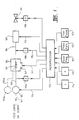
- FIG. 1 is a schematic block diagram illustrating the components of apparatus according to the invention and a control arrangement therefor.
- the apparatus comprises a flow-through liquid transport and containment means such as conduit 101 having an inlet section 102, intermediate section 103 and outlet or effluent section 104.
- the inlet section 102 includes a pump 105 that is controllably variable to deliver a feed liquid or slurry through conduit 101 at desired flow rates and pressures, and a pressure sensor 110a.
- Additional inlet conduits (e.g. 102a) and pumps (e.g.105a) may be provided to allow different reactants to be separately supplied for mixing within the intermediate section 103.
- the intermediate section 103 of conduit 101 is contained within a microwave heating zone 106 to which microwave energy of variable power or frequency is supplied by microwave generator 107.
- the microwave heating zone may consist of a suitable cavity adapted to permit observation of a reaction mixture as it passes through the intermediate section 103 of conduit 101.
- the intermediate section 103 of conduit 101 must be made of a material that is substantially transparent to microwaves.
- the outlet or effluent section 104 of conduit 101 includes a temperature sensing means 108 positioned such that the temperature of the feed liquid or slurry and entrained reaction product(s) is measured virtually immediately upon exit of such feed and products from the intermediate section 103.
- the temperature sensing means is so positioned because it is highly desirable that the temperature at which the chemical reaction within the feed occurs be determined to allow as high a degree of control as possible over a reaction. Another possibility to ensure an accurate measurement of the temperature of a reaction is to use a fibre optic or infra-red temperature sensing device positioned to measure the temperature of the products within the intermediate section 103.
- the outlet or effluent section includes a heat exchange means 109.
- the cooling temperature of this means is electronically controlled, for example, by use of a Peltier cooling device, to avoid the use of liquid or gaseous cooling fluids or refrigerants.
- the outlet effluent section 104 includes a pressure control means 110 to allow a feed liquid or slurry to be conveyed through the apparatus under adjustable pressures.
- the apparatus includes a control means, such as microprocessor 112, operably interconnecting the pump 105, microwave generator 107, temperature sensing means 108 and pressure sensing means 110a and pressure control means 110.
- the control means 112 may also supply power as shown at 113 to a Peltier cooling device of heat exchanger 109.
- Microprocessor 112 includes the facility to selectively input predetermined operating parameters for the apparatus.
- an operator may preset the temperature for a reaction by the temperature setting means 114, and the microprocessor compares this set signal with a signal 115 from temperature sensor 108 to determine a difference signal which in turn is used to control any one or more of the inputs 116 (to the pump 105), 117 (to the microwave generator 107), or 118 (to the pressure control means 110) so as to vary the feed rate, microwave power level, microwave frequency or pressure to minimise the temperature difference signal and thereby maintain the temperature at the set value.
- microprocessor 112 may be a pressure level 120, microwave power level or frequency 121, and feed rate 122.
- a feedback arrangement similar to that described above for temperature control, may also be included to maintain the pressure of a reaction to a predetermined set level.
- the microprocessor 112 may also include a facility 123 to input to set time for operation of the apparatus.
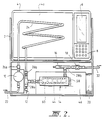
- FIG. 2 shows the layout of a microwave heating apparatus of the invention suitable for bench top laboratory use.
- the apparatus comprises a frame 2 (for mounting the various components of the apparatus) the upper section of which carries a microwave enclosure 4, associated magnetron (not shown) and control circuitry.
- the right hand margin of the microwave enclosure 4 includes a display 6, for example a liquid crystal display, which depicts operating parameters in real time as well as preset operating conditions.
- a touch pad 8 located below the display allows a set of operating parameters to be entered into a memory of the apparatus.
- the magnetron and suitable electronic control circuitry may be mounted to the right hand side of the enclosure 4 behind the display 6 and touch pad 8.
- the electronic control may include an appropriately programmed microprocessor or dedicated circuitry.
- the bottom section of frame 2 mounts the control devices of the flow through system.
- These control devices comprise feed pump 10 (for example a diaphragm metering pump capable of delivering 25 ml/min at 1200 KPa), thermocouple 12, cooling (heat exchange) means 14, pressure sensor-transducer 16 and pressure control valve 18 (for example a solenoid operated valve).
- the pressure control valve may be manually adjustable.
- a fan 20 is associated with the cooling means 14.
- the flow through system thus comprises an inlet end 22 connected to feed pump 10, the output of the pump being connected to an intermediate feed tube section 24 by a suitable connector 26a.
- the intermediate section 24 of the tube passes through the bottom wall of enclosure 4, into the cavity 4a of the microwave enclosure 4 and then passes out of the cavity through the bottom wall to another connector 26b.
- the intermediate section 24 may be easily removed and replaced by alternative sections of different material or configuration by disconnection and reconnection at connectors 26a and 26b.
- the material of intermediate section 24 may be any microwave transparent material suitable for the particular reaction or other task being undertaken within the apparatus. PTFE or borosilicate glass are particularly suitable.
- the intermediate section 24 may also be of any configuration and dimensions suitable for the task at hand.
- a preferred configuration is a coil and chemical reactions using coils made of PTFE tubing of various lengths, with an outside diameter of 6mm and inside diameter of 3mm have been used to carry out various chemical reactions at temperatures as high as 200 o C.
- Such a material and configuration has been found to be particularly suitable in achieving the result that the microwave energy heats substantially only the feed liquid or slurry within the intermediate section.
- a T-junction 28a is fitted to connector 26b, the thermocouple 12 being mounted in one arm of the T-junction.
- the other arm of the T-junction 28a is connected to the inlet of the cooling means 14.
- the outlet of the cooling means is connected to another T-junction 28b, in one arm of which is mounted the pressure transducer 16.
- the other arm of T-junction 28b leads to outlet 32 via the pressure control valve 18.
- Connectors 26a and 26b, T-junctions 28a and 28b, the inlet and outlet fittings of feed pump 10, the cooling means 14 and the pressure control valve 18 may be of stainless steel and lined with PTFE.
- the electronic heat exchange means 14 may comprise a number of Peltier cooling pads 44 mounted in heat conducting relationship to a side of a heat sink 46.
- the pads 44 may extend along the length of a cooling chamber 60 formed within block 58.
- Peltier pads which can provide a temperature gradient of 65 o C across their opposite faces are suitable for the present apparatus.
- the surfaces of the cooling chamber 60 which contact the reaction products are coated with PTFE.
- heat sink 46 may be maintained at about 60-75 o C (by intermittent or continuous operation of fan 20 as appropriate) such that a temperature differential of (say) 65 o C between the faces of Peltier pads 44 will produce a cooling temperature of about -5 to 10 o C at block 58 and thus within chamber 60.
- the reaction products within intermediate section 24, which may be at 200 o C, on leaving the microwave cavity enter (via T-junction 28a) the chamber 60 and thus may encounter a cooling temperature of between -5 to 10 o C.
- the actual cooling temperature may, of course, be preset and monitored by appropriate control circuitry.
- reactions that have been carried out using the above described apparatus are: oxidation, nucleophilic substitution, addition, esterification, transesterification, acetalisation, transketalisation, amidation, hydrolyses, isomerisation, condensation, decarboxylation, and elimination.
- the microwave apparatus according to the invention was fitted with a PTFE coil, 3 metres long, 6 mm o.d. and 3 mm i.d., with a volume of 23.8 ml (this coil constituting the intermediate section of the liquid transport means). Reaction conditions are given in parentheses in the order, flow rate in ml/min., temperature in o C, and pressure in kilopascals (kPa).
- Solvents were commercially available analytical grade and were not further treated before use.
- 2,4,6-Trimethylbenzoic acid (40.4 g.) was mixed with methanol (50ml) and the solution acidified with sulphuric acid (1.4ml), and passed through the CMR (15.5 ml/min., 162-5 o C, 1000 kPa). After four successive passes (total residence time 6 min.), the solution was found to contain 11% methyl 2,4,6-trimethylbenzoate by 1H NMR.
- the product mixture was poured onto cold aqueous NaOH solution (50g in 160ml of water) and the organic phase separated and analysed by GC-MS and 1H NMR. A conversion of 66% was obtained.
- the reaction mixture was heated on a steam bath for four hours and held at room temperature for an additional twenty four hours9.
- Morpholine (157g; 1.8 mol.) and cyclohexanone (147g; 1.5 mol.) were mixed with toluene (300ml). Finely ground p-toluenesulphonic acid (1.5g) was then added and the mixture stirred and pumped through the CMR (15 ml/min.; 103-4 o C; 1000-1200 kPa). The yield of 4-(1-cyclohex-1-enyl) morpholine was estimated by GC-MC as 25%; cf lit.14.
- Paraformaldehyde 100g was mixed with water (300ml) and concentrated hydrochloric acid (3ml). This mixture was stirred vigorously and pumped through the CMR (about 13 ml/min; 150-170 o C; 1000 kPa), yielding a clear solution (380ml) containing 25% formaldehyde as determined by wet chemical analysis.
- N-(2-benzoylethyl)-N,N,N-trimethylammonium iodide (5.0g) was suspended in water (400ml) and the mixture passed through the CMR (15 ml/min; 90-95 o C; atmospheric pressure) and the hot product collected in a mixture of ice (250g) and diethyl ether (100ml), in a flask which was cooled in an ice bath. The ether phase was separated and the aqueous extracted with ether (3 x 150ml).
- Citronellal (5.9ml) was added to a mixture of hydroxylamine hydrochloride (3.2g) in water (100ml) containing sodium hydrogen carbonate (8.4g) and the material pumped through the CMR (20.5 ml/min; 137-40 o C; 500-550 kPa).
- GC-MS showed a 95% conversion to a mixture of the two oximes.
Landscapes
- Chemical & Material Sciences (AREA)
- Organic Chemistry (AREA)
- Physics & Mathematics (AREA)
- Electromagnetism (AREA)
- Health & Medical Sciences (AREA)
- General Health & Medical Sciences (AREA)
- Chemical Kinetics & Catalysis (AREA)
- Clinical Laboratory Science (AREA)
- Toxicology (AREA)
- Physical Or Chemical Processes And Apparatus (AREA)
- Organic Low-Molecular-Weight Compounds And Preparation Thereof (AREA)
Claims (31)
- Verfahren zur Durchführung chemischer Reaktionen, also Oxidations-, nucleophile Substitutions-, Additions-, Veresterungs-, Umesterungs-, Acetalisierungs-, Umketalisierungs-, Amidierungs-, Hydrolyse-, Isomerisierungs-, Kondensations-, Decarboxylietungs- oder Eliminierungsreaktionen, auf kontinuierliche Weise, umfassend:(i) Vorsehen einer Zulauflüssigkeit oder -aufschlämmung mit einem darin befindlichen Reaktanten, welcher in der Lage ist, Mikrowellenstrahlung zu absorbieren, wobei die Zulaufflüssigkeit oder -aufschlämmung mindestens einen Reaktanten enthält,(ii) kontinuierliches Zuführen der Flüssigkeit oder Aufschlämmung einer und durch eine Mikrowellenheizzone unter Druck,(iii) Anwenden von Mikrowellenenergie auf den Zulauf innerhalb der Mikrowellenheizzone,(iv) Regulieren der Menge der Mikrowellenenergie, zusammen mit dem Zulaufdruck und/oder der Zulaufrate, um sicherzustellen, daß die vom Reaktanten absorbierte Energie eine innerhalb des Zulaufs auftretende chemische Reaktion verursacht, und (v) Gewinnen der Produkte der chemischen Reaktion aus dem Zulauf.
- Verfahren nach Anspruch 1, bei dem die chemische Reaktion durch Regulierung der Temperatur des Zulaufs innerhalb der Heizzone reguliert wird.
- Verfahren nach Anspruch 1, bei dem eines oder mehrere des Drucks/der Fließrate des Zulaufs oder der Mikrowellenleistung oder der Mikrowellenfrequenz derart reguliert werden, daß eine gewünschte chemische Reaktion bei einer vorbestimmten Temperatur abläuft, wobei die Reaktionsprodukte in dem Zulauf mitgeführt werden und darin von der Mikrowellenzone entfernt werden.
- Verfahren nach Anspruch 1, bei dem die abfließende Zulaufflüssigkeit oder -aufschlämmung und mitgeführte(s) Reaktionsprodukt(e) im wesentlichen sofort nach dem Austritt aus der Mikrowellenzone abgekühlt werden.
- Verfahren nach Anspruch 4, bei dem die abfließende Zulaufflüssigkeit oder -aufschlämmung und (das) mitgeführte Reaktionsprodukt(e) während des Durchlaufs durch eine Wärmeaustauschvorrichtung, dessen Kühltemperatur elektronisch reguliert wird, gekühlt werden.
- Verfahren nach Anspruch 3, bei dem mindestens eines oder mehrere der Zulauffließrate oder des -drucks oder der Mikrowellenleistung oder der Mikrowellenfrequenz in regulierbarer bzw. steuerbarer Weise als Reaktion auf ein Temperaturabweichsignal variiert werden können.
- Verfahren nach Anspruch 6, bei dem das Temperaturabweichsignal von einem voreingestellten Temperaturwert und der gemessenen Temperatur des Reaktionsprodukts (der Reaktionsprodukte) stammt, wobei die gemessene Temperatur im wesentlichen vor Kühlung des Reaktionsprodukts (der Reaktionsprodukte) bestimmt wird.
- Verfahren nach Anspruch 1, bei dem der Druck der Zulaufflüssigkeit oder -aufschlämmung und somit der Druck für die chemische Reaktion auf einen voreingestellten Wert gehalten wird.
- Verfahren nach mindestens einem der vorhergehenden Ansprüche, bei dem die Zulaufflüssigkeit oder -aufschlämmung mindestens zwei Reaktanten enthält.
- Verfahren nach Anspruch 9, bei dem die Reaktanten durch getrennte Eintrittsöffnungen zugeführt und miteinander innerhalb der Mikrowellenheizzone kombiniert werden.
- Verfahren nach Anspruch 1, bei dem die chemische Reaktion eine Veresteningsreaktion ist.
- Verfahren nach Anspruch 11, bei dem die Reaktion in Abwesenheit eines Katalysators durchgeführt wird.
- Verfahren nach Anspruch 12, bei dem der flüssige Zulauf Essigsäure und Ethanol umfaßt und das Reaktionsprodukt Ethylacetat ist.
- Verfahren nach Anspruch 1, bei dem die chemische Reaktion eine Aminomethylierungsreaktion ist.
- Verfahren nach Anspruch 1, bei dem die chemische Reaktion eine nucleophile Substitution ist.
- Verfahren nach Anspruch 15, bei dem der flüssige Zulauf Natriumphenolat und Benzylchlorid umfaßt und das Reaktionsprodukt Benzylphenylether ist.
- Verfahren nach Anspruch 1, bei dem die chemische Reaktion eine Depolymerisationsreaktion ist.
- Verfahren nach Anspruch 1, bei dem die chemische Reaktion eine Hofmann-Eliminierung ist.
- Verfahren nach Anspruch 1, bei dem der flüssige Zulauf Maltol und Methylamin in Wasser umfaßt und das Reaktionsprodukt 1,2-Dimethyl-3-hydroxypyrid-4-on ist.
- Verfahren nach Anspruch 1, bei dem der flüssige Zulauf in Wasser gelöste Chromotropsäure und Formaldehyd umfaßt.
- Verfahren nach Anspruch 1, bei dem die chemische Reaktion eine Acetalbildung ist.
- Verfahren nach Anspruch 1, bei dem die chemische Reaktion eine Isomerisierungsreaktion ist.
- Verfahren nach Anspruch 1, bei dem die chemische Reaktion eine Knoevenagel-Reaktion ist.
- Verfahren nach Anspruch 1, bei dem die chemische Reaktion eine Reaktion zur Bildung eines Oxims ist.
- Apparatur zur Durchführung des Verfahrens nach Anspruch 1, umfassend:(i) Flüssigkeittransport- und Einschlußvorrichtung mit einem Eintrittsteil, Zwischenteil und einem Austritts- oder Abflußteil, die einen Flüssigkeitsstrom mit Einrichtungsdurchlauf durch die Apparatur bereitstellt,(ii) Zuführvorrichtung zum Zuführen einer Flüssigkeit oder Aufschlämmung mit einer regulierbar variablen Rate durch die Flüssigkeittransport- und Einschlußvorrichtung,(iii) ein Mikrowellengenerator, der die Mikrowellenenergie dem Zwischenteil zuführt,(iv) Vorrichtung zur Temperaturmessung, die mit dem Zwischen- oder Abflußteil verbunden ist, um die Temperatur des Produkts (der Produkte) einer chemischen Reaktion zu messen, und(v) eine Vorrichtung zur Druckregulierung,dadurch charakterisiert, daß die Apparatur ebenfalls(vi) eine Wärmeaustauschvorrichtung im Ablußteil einschließt, um den abfließenden Zulauf und das mitgeführte Produkt (die mitgeführten Produkte) sofort nach Austritt aus dem Zwischenteil zu kühlen.
- Apparatur gemäß Anspruch 25, die eine die Zuführvorrichtung, die Vorrichtung zur Temperaturmessung, die Vorrichtung zur Druckmessung und den Mikrowellengenerator betriebsbeeinflussend miteinander verbindende Steuervorrichtung einschließt, so daß mindestens eine der Variablen aus Fließrate oder Druck einer Zulaufflüssigkeit oder -aufschlämmung, der Mikrowellenenergie oder der Temperatur einer chemischen Reaktion im Zulauf regulierbar als Reaktion auf die Abweichung bei einer anderen der Variablen von einem voreingestellten Wert variiert werden kann, um dadurch die andere Variable im wesentlichen auf dem voreingestellten Wert zu halten.
- Apparatur nach Anspruch 26, bei der die Steuervorrichtung ein Mikroprozessor ist.
- Apparatur nach Anspruch 26, bei der die Steuervorrichtung eine Vorrichtung einschließt, um den Mikrowellengenerator zur Veränderung der Mikrowellenenergie ein- und auszuschalten.
- Apparatur nach Anspruch 26, bei der die Steuervorrichtung eine Vorrichtung einschließt, um den Leistungsgrad oder die Frequenz der vom Mikrowellengenerator zugeführten Mikrowellenenergie zu verändern.
- Apparatur nach Anspruch 25, bei der der Eintrittsteil der Flüssigkeittransport- und Einschlußvorrichtung eine Vorrichtung zur getrennten Zuführung unterschiedlicher Reaktanten und zum Mischen innerhalb des Zwischenteils umfaßt.
- Apparatur nach Anspruch 25, bei der die Wärmeaustauschvorrichtung eine elektronische Vorrichtung ist.
Applications Claiming Priority (6)
| Application Number | Priority Date | Filing Date | Title |
|---|---|---|---|
| AUPJ087288 | 1988-10-10 | ||
| AU872/88 | 1988-10-10 | ||
| AU5057/89 | 1989-07-04 | ||
| AUPJ505789 | 1989-07-04 | ||
| PCT/AU1989/000437 WO1990003840A1 (en) | 1988-10-10 | 1989-10-09 | Method and apparatus for continuous chemical reactions |
| US07/892,996 US5387397A (en) | 1988-10-10 | 1992-06-03 | Method and apparatus for continuous chemical reactions |
Publications (3)
| Publication Number | Publication Date |
|---|---|
| EP0437480A1 EP0437480A1 (de) | 1991-07-24 |
| EP0437480A4 EP0437480A4 (en) | 1991-10-30 |
| EP0437480B1 true EP0437480B1 (de) | 1994-10-19 |
Family
ID=27157459
Family Applications (1)
| Application Number | Title | Priority Date | Filing Date |
|---|---|---|---|
| EP89911229A Expired - Lifetime EP0437480B1 (de) | 1988-10-10 | 1989-10-09 | Verfahren und vorrichtung für kontinuierliche chemische reaktionen |
Country Status (6)
| Country | Link |
|---|---|
| US (1) | US5387397A (de) |
| EP (1) | EP0437480B1 (de) |
| AT (1) | ATE112978T1 (de) |
| CA (1) | CA2000351C (de) |
| DE (1) | DE68918950T2 (de) |
| WO (1) | WO1990003840A1 (de) |
Cited By (7)
| Publication number | Priority date | Publication date | Assignee | Title |
|---|---|---|---|---|
| US8884040B2 (en) | 2008-04-04 | 2014-11-11 | Clariant Finance (Bvi) Limited | Continuous method for producing fatty acid amides |
| US8974743B2 (en) | 2009-06-30 | 2015-03-10 | Clariant Finance (Bvi) Limited | Device for continuously carrying out chemical reactions at high temperatures |
| US9000197B2 (en) | 2009-09-22 | 2015-04-07 | Clariant Finance (Bvi) Limited | Continuous transesterification method |
| US9039870B2 (en) | 2006-10-09 | 2015-05-26 | Clariant Finance (Bvi) Limited | Method for producing alkaline (meth)acrylamides |
| US9221938B2 (en) | 2010-12-30 | 2015-12-29 | Clariant Finance (Bvi) Limited | Polymers carrying hydroxyl groups and ester groups and method for the production thereof |
| US9243116B2 (en) | 2010-12-30 | 2016-01-26 | Clariant International Ltd. | Method for modifying polymers comprising hydroxyl groups |
| US9302245B2 (en) | 2009-09-22 | 2016-04-05 | Clariant International Ltd. | Apparatus for continuously carrying out heterogeneously catalyzed chemical reactions at elevated temperatures |
Families Citing this family (68)
| Publication number | Priority date | Publication date | Assignee | Title |
|---|---|---|---|---|
| FR2665264A1 (fr) * | 1990-07-24 | 1992-01-31 | Prolabo Sa | Procede pour realiser une reaction chimique par voie humide sur une succession d'echantillons, appareil pour la mise en óoeuvre du procede et utilisation dudit appareil. |
| FR2697448B1 (fr) * | 1992-10-30 | 1995-06-16 | Moulinex Sa | Dispositif de conduite d'opérations chimiques. |
| US5420039A (en) * | 1992-12-31 | 1995-05-30 | Cem Corporation | Control of continuous microwave digestion process |
| CA2160929A1 (en) * | 1993-05-05 | 1994-11-10 | Mohamad Mallah | Process and plant for the manufacture of solid castings from an essentially liquid reactive medium, and oven for heating an essentially liquid medium |
| CA2162255A1 (en) * | 1993-05-11 | 1994-11-24 | Srl, Inc. | Microwave irradiation method and microwave irradiation device |
| US5725835A (en) * | 1993-11-11 | 1998-03-10 | Lautenschlaeger; Werner | Device for initiating and/or promoting chemical or physical processes in a material |
| US5470541A (en) * | 1993-12-28 | 1995-11-28 | E. I. Du Pont De Nemours And Company | Apparatus and process for the preparation of hydrogen cyanide |
| US5689008A (en) * | 1996-02-02 | 1997-11-18 | United Technologies Corporation | Catalytic reaction rate enhancement at low temperatures |
| DE19631201C2 (de) * | 1996-08-02 | 2001-07-05 | Rainer Buchholz | Verfahren und Reaktor zur Umwandlung von Biomasse in flüssige, feste oder gasförmige Brennstoffe und Chemierohstoffe |
| US6207408B1 (en) * | 1997-08-20 | 2001-03-27 | University Of Miami | High quality, continuous throughput, tissue fixation-dehydration-fat removal-impregnation method |
| US6793890B2 (en) | 1997-08-20 | 2004-09-21 | The University Of Miami | Rapid tissue processor |
| US6031100A (en) * | 1997-09-18 | 2000-02-29 | Bayer Corporation | Microwave syntheses of quinacridones, 6,13-Dihydroquinacridones, and 6,13-quinacridonequinones |
| US6084226A (en) | 1998-04-21 | 2000-07-04 | Cem Corporation | Use of continuously variable power in microwave assisted chemistry |
| US6175037B1 (en) | 1998-10-09 | 2001-01-16 | Ucb, S.A. | Process for the preparation of (meth)acrylate esters and polyester (meth)acrylates using microwave energy as a heating source |
| FR2791670A1 (fr) * | 1999-03-31 | 2000-10-06 | Rhodia Chimie Sa | Procede d'activation de substrats aromatiques par micro-ondes |
| KR100411194B1 (ko) * | 2000-11-03 | 2003-12-18 | 한국화학연구원 | 연속식 마이크로파 합성법을 이용한 무기소재의 제조방법및 그 장치 |
| AU2001260518A1 (en) * | 2000-05-08 | 2001-11-20 | Personal Chemistry I Uppsala Ab. | Method for performing multiple chemical reactions and a kit and system therefor |
| WO2003041856A1 (en) * | 2001-10-19 | 2003-05-22 | Personal Chemistry I Uppsala Ab | Continuous flow system with microwave heating |
| US20030091487A1 (en) * | 2001-10-19 | 2003-05-15 | Magnus Fagrell | Continuous flow heating system |
| FR2839069B1 (fr) * | 2002-04-25 | 2006-04-07 | Satie Sa | Nouveaux procedes de transesterification, esterification, interesterification, par chauffage dielectrique |
| US6744024B1 (en) | 2002-06-26 | 2004-06-01 | Cem Corporation | Reaction and temperature control for high power microwave-assisted chemistry techniques |
| US6867400B2 (en) * | 2002-07-31 | 2005-03-15 | Cem Corporation | Method and apparatus for continuous flow microwave-assisted chemistry techniques |
| US7387712B2 (en) * | 2002-10-17 | 2008-06-17 | Carnegie Mellon University | Catalytic process for the treatment of organic compounds |
| US20040074760A1 (en) * | 2002-10-17 | 2004-04-22 | Carnegie Mellon University | Production of biofuels |
| US7157401B2 (en) * | 2002-10-17 | 2007-01-02 | Carnegie Mellon University | Catalyst for the treatment of organic compounds |
| CA2510334A1 (en) * | 2002-12-18 | 2004-07-01 | Biotage Ab | Method and apparatus for control of chemical reactions |
| JP4413783B2 (ja) * | 2002-12-19 | 2010-02-10 | カウンシル オブ サイエンティフィック アンド インダストリアル リサーチ | 置換4−ビニルフェノール調製のための、マイクロ波に誘発されるプロセス |
| FR2849343B1 (fr) * | 2002-12-23 | 2009-01-23 | Aldivia | Synthese chimique comportant un traitement thermique par chauffage dielectrique intermittent, combine a un systeme de recirculation |
| US7393920B2 (en) | 2003-06-23 | 2008-07-01 | Cem Corporation | Microwave-assisted peptide synthesis |
| FR2858616B1 (fr) * | 2003-08-07 | 2006-02-17 | Aldivia Sa | Procede d'estolidation par chauffage dielectrique |
| US7041947B2 (en) * | 2003-09-02 | 2006-05-09 | Cem Corporation | Controlled flow instrument for microwave assisted chemistry with high viscosity liquids and heterogeneous mixtures |
| US6989519B2 (en) * | 2003-09-02 | 2006-01-24 | Cem Corporation | Controlled flow instrument for microwave assisted chemistry with high viscosity liquids and heterogeneous mixtures |
| DE602004023104D1 (de) * | 2003-10-24 | 2009-10-22 | Univ Miami | Vereinfachte gewebeverarbeitung |
| EE200400060A (et) * | 2004-02-25 | 2005-10-17 | Nordic Alternative Energy OÜ | Meetod ja seade karboksüülhapete estrite pidevaprotsessiliseks transesterifikatsioonikssuperkriitilises monovalentses alkoholis |
| US20050274065A1 (en) * | 2004-06-15 | 2005-12-15 | Carnegie Mellon University | Methods for producing biodiesel |
| CN102311532A (zh) * | 2005-05-24 | 2012-01-11 | 日立化成工业株式会社 | 共轭聚合物的制造方法 |
| KR100693126B1 (ko) * | 2005-07-14 | 2007-03-13 | 한국화학연구원 | 다공성 물질 및 혼합 금속산화물의 연속적 제조방법 및연속적 제조 장치 |
| GB0608512D0 (en) | 2006-04-28 | 2006-06-07 | Vincent Processes Ltd | Process for the production of esters of sugars and sugar derivatives |
| US7641860B2 (en) * | 2006-06-01 | 2010-01-05 | Nanotek, Llc | Modular and reconfigurable multi-stage microreactor cartridge apparatus |
| US7998418B1 (en) | 2006-06-01 | 2011-08-16 | Nanotek, Llc | Evaporator and concentrator in reactor and loading system |
| US7854902B2 (en) * | 2006-08-23 | 2010-12-21 | Nanotek, Llc | Modular and reconfigurable multi-stage high temperature microreactor cartridge apparatus and system for using same |
| DE102006047619B4 (de) * | 2006-10-09 | 2008-11-13 | Clariant International Limited | Verfahren zur Herstellung basischer Fettsäureamide |
| US7797988B2 (en) | 2007-03-23 | 2010-09-21 | Advion Biosystems, Inc. | Liquid chromatography-mass spectrometry |
| DE102008017214B4 (de) * | 2008-04-04 | 2012-02-16 | Clariant International Limited | Kontinuierliches Verfahren zur Herstellung von Fettsäurealkanolamiden |
| DE102008017217A1 (de) * | 2008-04-04 | 2009-10-08 | Clariant International Ltd. | Kontinuierliches Verfahren zur Herstellung von Amiden aromatischer Carbonsäuren |
| DE102008017219A1 (de) * | 2008-04-04 | 2009-10-08 | Clariant International Ltd. | Verfahren zur Herstellung von Amiden in Gegenwart von überhitztem Wasser |
| DE102008017213B4 (de) * | 2008-04-04 | 2012-08-09 | Clariant International Limited | Kontinuierliches Verfahren zur Herstellung von Amiden aliphatischer Hydroxycarbonsäuren |
| DE102008017218B4 (de) * | 2008-04-04 | 2011-09-22 | Clariant International Ltd. | Kontinuierliches Verfahren zur Herstellung von Amiden niederer aliphatischer Carbonsäuren |
| DE102008017215B4 (de) * | 2008-04-04 | 2012-08-09 | Clariant International Ltd. | Kontinuierliches Verfahren zur Herstellung von Amiden ethylenisch ungesättigter Carbonsäuren |
| US20090298172A1 (en) * | 2008-05-28 | 2009-12-03 | Steven Paul Wheeler | Histological specimen treatment apparatus and method |
| WO2010039466A2 (en) * | 2008-09-23 | 2010-04-08 | James Michael Drozd | Electromagnetic system |
| EP2382039B1 (de) * | 2009-01-26 | 2012-06-06 | Cambrex Karlskoga AB | Mikrowellenvorrichtung |
| JP5107278B2 (ja) * | 2009-02-16 | 2012-12-26 | 株式会社日立製作所 | マイクロ波加熱装置および加熱方法 |
| DE102009031056A1 (de) * | 2009-06-30 | 2011-01-27 | Clariant International Ltd. | Kontinuierliches Verfahren zur Acrylierung von Aminogruppen tragenden organischen Säuren |
| DE102009031058A1 (de) | 2009-06-30 | 2011-01-27 | Clariant International Ltd. | Kontinuierliches Verfahren zur Herstellung von Amiden aromatischer Carbonsäuren |
| DE102009031053A1 (de) | 2009-06-30 | 2011-01-13 | Clariant International Ltd. | Kontinuierliches Verfahren zur Herstellung von Estern aliphatischer Carbonsäuren |
| DE102009031054A1 (de) | 2009-06-30 | 2011-01-13 | Clariant International Ltd. | Kontinuierliches Verfahren zur Herstellung von Estern aromatischer Carbonsäuren |
| DE102009031057A1 (de) | 2009-06-30 | 2011-01-05 | Clariant International Ltd. | Kontinuierliches Verfahren zur Herstellung von Amiden aliphatischer Carbonsäuren |
| DE102009033216A1 (de) | 2009-07-15 | 2011-01-27 | Brümmer, Heinz | Vorrichtung und Verfahren zur Herstellung von Leichtölen aus Biomasse und kohlenwasserstoffhaltigen Stoffen mittels Verpressen der Reaktionsmasse zusammen mit einem zeolithischen Katalysator als Reaktionsbeschleuniger zu Pellets und anschließender Molekülverkürzung der Reaktionsmasse durch von Mikrowellenstrahlung initiiertem Plasma in einem Flachbettreaktor |
| DE102010056566A1 (de) | 2010-12-30 | 2012-07-05 | Clariant International Ltd. | Kontinuierliches Verfahren zur Veresterung Säuregruppen tragender Polymere |
| CN102260170B (zh) * | 2011-06-02 | 2014-10-15 | 浙江大学 | 微波管道化生产乙酸正t酯的方法 |
| EP2820170B1 (de) * | 2012-02-28 | 2016-03-23 | Inventram Fikri Mulkiyet Haklari Yonetim Ticaret Ve Yatirim Anonim Sirketi | Anordnung für zeolithbeschichtungszubereitung und betriebsverfahren |
| US10450259B2 (en) | 2013-06-26 | 2019-10-22 | University Of Virginia Patent Foundation | Compositions and methods for hydrocarbon functionalization |
| EP3006103A1 (de) * | 2014-10-06 | 2016-04-13 | Paul Scherrer Institut | Verfahren zur Herstellung metallorganischer Rahmen und kovalenter organischer Rahmen |
| US10365189B2 (en) | 2015-05-07 | 2019-07-30 | Steven Wheeler | Histological specimen treatment |
| US12485401B2 (en) * | 2019-11-04 | 2025-12-02 | Max-Planck-Gesellschaft zur F6rderung der Wissenschaften e.V. | Synthesizer for oligo- and polysaccharides on solid phase |
| CN111117676B (zh) * | 2020-01-19 | 2025-06-24 | 中国林业科学研究院林产化学工业研究所 | 一种微波连续调频协同生物质定向解聚装置及其使用方法 |
| CN116520712B (zh) * | 2023-07-03 | 2023-08-22 | 贵阳职业技术学院 | 一种反应容器入料量自适应调控方法、系统、终端及介质 |
Family Cites Families (7)
| Publication number | Priority date | Publication date | Assignee | Title |
|---|---|---|---|---|
| US3535482A (en) * | 1968-06-26 | 1970-10-20 | Hammtronics Systems Inc | Microwave apparatus for rapid heating of fluids |
| GB1371400A (en) * | 1972-06-14 | 1974-10-23 | Camph Eng Co Ab | Method of heating blood |
| NL7509305A (nl) * | 1974-08-07 | 1976-02-10 | British Petroleum Co | Werkwijze voor het tot stand brengen van chemische reacties. |
| AU521896B2 (en) * | 1976-11-17 | 1982-05-06 | Jean, O.A.L. | Apparatus for subjecting a material to electromagnetic waves |
| AU7556981A (en) * | 1976-12-23 | 1981-12-24 | Kenneth Frederick Currie | Irradiation unit |
| US4353890A (en) * | 1979-10-24 | 1982-10-12 | Colgate-Palmolive Company | Stabilization of carrageenan-containing toothpaste |
| GB2098040A (en) * | 1981-03-31 | 1982-11-10 | Sanyo Electric Co | System for and method of sterilization of food material |
-
1989
- 1989-10-09 WO PCT/AU1989/000437 patent/WO1990003840A1/en not_active Ceased
- 1989-10-09 DE DE68918950T patent/DE68918950T2/de not_active Expired - Fee Related
- 1989-10-09 AT AT89911229T patent/ATE112978T1/de not_active IP Right Cessation
- 1989-10-09 EP EP89911229A patent/EP0437480B1/de not_active Expired - Lifetime
- 1989-10-10 CA CA002000351A patent/CA2000351C/en not_active Expired - Fee Related
-
1992
- 1992-06-03 US US07/892,996 patent/US5387397A/en not_active Expired - Lifetime
Cited By (7)
| Publication number | Priority date | Publication date | Assignee | Title |
|---|---|---|---|---|
| US9039870B2 (en) | 2006-10-09 | 2015-05-26 | Clariant Finance (Bvi) Limited | Method for producing alkaline (meth)acrylamides |
| US8884040B2 (en) | 2008-04-04 | 2014-11-11 | Clariant Finance (Bvi) Limited | Continuous method for producing fatty acid amides |
| US8974743B2 (en) | 2009-06-30 | 2015-03-10 | Clariant Finance (Bvi) Limited | Device for continuously carrying out chemical reactions at high temperatures |
| US9000197B2 (en) | 2009-09-22 | 2015-04-07 | Clariant Finance (Bvi) Limited | Continuous transesterification method |
| US9302245B2 (en) | 2009-09-22 | 2016-04-05 | Clariant International Ltd. | Apparatus for continuously carrying out heterogeneously catalyzed chemical reactions at elevated temperatures |
| US9221938B2 (en) | 2010-12-30 | 2015-12-29 | Clariant Finance (Bvi) Limited | Polymers carrying hydroxyl groups and ester groups and method for the production thereof |
| US9243116B2 (en) | 2010-12-30 | 2016-01-26 | Clariant International Ltd. | Method for modifying polymers comprising hydroxyl groups |
Also Published As
| Publication number | Publication date |
|---|---|
| DE68918950D1 (de) | 1994-11-24 |
| WO1990003840A1 (en) | 1990-04-19 |
| CA2000351C (en) | 1999-11-30 |
| DE68918950T2 (de) | 1995-03-16 |
| EP0437480A4 (en) | 1991-10-30 |
| EP0437480A1 (de) | 1991-07-24 |
| US5387397A (en) | 1995-02-07 |
| CA2000351A1 (en) | 1990-04-10 |
| ATE112978T1 (de) | 1994-11-15 |
Similar Documents
| Publication | Publication Date | Title |
|---|---|---|
| EP0437480B1 (de) | Verfahren und vorrichtung für kontinuierliche chemische reaktionen | |
| Cablewski et al. | Development and application of a continuous microwave reactor for organic synthesis | |
| CN102448603B (zh) | 用于在高温下连续进行化学反应的设备 | |
| EP1515799B1 (de) | Reaktions und temperaturregelung für hoch leistungs, mikrowellen-assistierte chemische verfahren | |
| AU677876B2 (en) | Batch microwave reactor | |
| CN101918355B (zh) | 制备芳族羧酸的酰胺的连续方法 | |
| JPWO2005102510A1 (ja) | マイクロ波を応用した化学反応装置 | |
| US20110137081A1 (en) | Continuous Method For Producing Amides Of Low Aliphatic Carboxylic Acids | |
| KR20100135227A (ko) | 지방족 하이드록시카복실산의 아미드의 연속 제조방법 | |
| WO2016091157A1 (zh) | 一种使用同轴裂缝天线的微波反应装置及其应用 | |
| US20120108818A1 (en) | Microwave apparatus | |
| Leadbeater et al. | Use of a scientific microwave apparatus for rapid optimization of reaction conditions in a monomode function and then substrate screening in a multimode function | |
| AU635903B2 (en) | Method and apparatus for continuous chemical reactions | |
| EP1996539B1 (de) | Verfahren und vorrichtung zur durchführung mikrowellenunterstützter organischer reaktionen mit gasphasenreaktanten | |
| US20030091487A1 (en) | Continuous flow heating system | |
| WO2003041856A1 (en) | Continuous flow system with microwave heating | |
| KR970010331B1 (ko) | 연속 화학반응을 위한 방법 및 장치 | |
| RU187166U1 (ru) | Лабораторно-исследовательский стенд для изучения процессов дегидратации углеводов | |
| KR102543628B1 (ko) | 마이크로웨이브 반응 장치 | |
| US20060151493A1 (en) | Method and apparatus for control of chemical reactions | |
| CN215464449U (zh) | 一种制备丙硫菌唑的塔式反应器 | |
| CN107051347A (zh) | 一种微波耦合反应的装置及其应用 | |
| CN224113949U (zh) | 一种微波连续反应装置 | |
| CN102861544A (zh) | 一种微波辅助的合成反应装置 |
Legal Events
| Date | Code | Title | Description |
|---|---|---|---|
| PUAI | Public reference made under article 153(3) epc to a published international application that has entered the european phase |
Free format text: ORIGINAL CODE: 0009012 |
|
| 17P | Request for examination filed |
Effective date: 19910408 |
|
| AK | Designated contracting states |
Kind code of ref document: A1 Designated state(s): AT BE CH DE FR GB IT LI LU NL SE |
|
| A4 | Supplementary search report drawn up and despatched |
Effective date: 19910910 |
|
| AK | Designated contracting states |
Kind code of ref document: A4 Designated state(s): AT BE CH DE FR GB IT LI LU NL SE |
|
| 17Q | First examination report despatched |
Effective date: 19921116 |
|
| GRAA | (expected) grant |
Free format text: ORIGINAL CODE: 0009210 |
|
| AK | Designated contracting states |
Kind code of ref document: B1 Designated state(s): AT BE CH DE FR GB IT LI LU NL SE |
|
| REF | Corresponds to: |
Ref document number: 112978 Country of ref document: AT Date of ref document: 19941115 Kind code of ref document: T |
|
| ITF | It: translation for a ep patent filed | ||
| REF | Corresponds to: |
Ref document number: 68918950 Country of ref document: DE Date of ref document: 19941124 |
|
| ET | Fr: translation filed | ||
| EAL | Se: european patent in force in sweden |
Ref document number: 89911229.6 |
|
| PLBE | No opposition filed within time limit |
Free format text: ORIGINAL CODE: 0009261 |
|
| STAA | Information on the status of an ep patent application or granted ep patent |
Free format text: STATUS: NO OPPOSITION FILED WITHIN TIME LIMIT |
|
| 26N | No opposition filed | ||
| REG | Reference to a national code |
Ref country code: GB Ref legal event code: IF02 |
|
| PGFP | Annual fee paid to national office [announced via postgrant information from national office to epo] |
Ref country code: NL Payment date: 20051003 Year of fee payment: 17 |
|
| PGFP | Annual fee paid to national office [announced via postgrant information from national office to epo] |
Ref country code: SE Payment date: 20051005 Year of fee payment: 17 |
|
| PGFP | Annual fee paid to national office [announced via postgrant information from national office to epo] |
Ref country code: FR Payment date: 20051010 Year of fee payment: 17 |
|
| PGFP | Annual fee paid to national office [announced via postgrant information from national office to epo] |
Ref country code: CH Payment date: 20051014 Year of fee payment: 17 |
|
| PGFP | Annual fee paid to national office [announced via postgrant information from national office to epo] |
Ref country code: LU Payment date: 20051031 Year of fee payment: 17 |
|
| PGFP | Annual fee paid to national office [announced via postgrant information from national office to epo] |
Ref country code: BE Payment date: 20051215 Year of fee payment: 17 |
|
| PG25 | Lapsed in a contracting state [announced via postgrant information from national office to epo] |
Ref country code: SE Free format text: LAPSE BECAUSE OF NON-PAYMENT OF DUE FEES Effective date: 20061010 |
|
| PG25 | Lapsed in a contracting state [announced via postgrant information from national office to epo] |
Ref country code: CH Free format text: LAPSE BECAUSE OF NON-PAYMENT OF DUE FEES Effective date: 20061031 Ref country code: LI Free format text: LAPSE BECAUSE OF NON-PAYMENT OF DUE FEES Effective date: 20061031 |
|
| PGFP | Annual fee paid to national office [announced via postgrant information from national office to epo] |
Ref country code: IT Payment date: 20061031 Year of fee payment: 18 |
|
| PGFP | Annual fee paid to national office [announced via postgrant information from national office to epo] |
Ref country code: GB Payment date: 20070201 Year of fee payment: 18 |
|
| PGFP | Annual fee paid to national office [announced via postgrant information from national office to epo] |
Ref country code: AT Payment date: 20070222 Year of fee payment: 18 |
|
| PGFP | Annual fee paid to national office [announced via postgrant information from national office to epo] |
Ref country code: DE Payment date: 20070223 Year of fee payment: 18 |
|
| PG25 | Lapsed in a contracting state [announced via postgrant information from national office to epo] |
Ref country code: NL Free format text: LAPSE BECAUSE OF NON-PAYMENT OF DUE FEES Effective date: 20070501 |
|
| REG | Reference to a national code |
Ref country code: CH Ref legal event code: PL |
|
| EUG | Se: european patent has lapsed | ||
| NLV4 | Nl: lapsed or anulled due to non-payment of the annual fee |
Effective date: 20070501 |
|
| REG | Reference to a national code |
Ref country code: FR Ref legal event code: ST Effective date: 20070629 |
|
| BERE | Be: lapsed |
Owner name: *COMMONWEALTH SCIENTIFIC AND INDUSTRIAL RESEARCH O Effective date: 20061031 |
|
| PG25 | Lapsed in a contracting state [announced via postgrant information from national office to epo] |
Ref country code: FR Free format text: LAPSE BECAUSE OF NON-PAYMENT OF DUE FEES Effective date: 20061031 |
|
| GBPC | Gb: european patent ceased through non-payment of renewal fee |
Effective date: 20071009 |
|
| PG25 | Lapsed in a contracting state [announced via postgrant information from national office to epo] |
Ref country code: LU Free format text: LAPSE BECAUSE OF NON-PAYMENT OF DUE FEES Effective date: 20061009 Ref country code: DE Free format text: LAPSE BECAUSE OF NON-PAYMENT OF DUE FEES Effective date: 20080501 |
|
| PG25 | Lapsed in a contracting state [announced via postgrant information from national office to epo] |
Ref country code: AT Free format text: LAPSE BECAUSE OF NON-PAYMENT OF DUE FEES Effective date: 20071009 |
|
| PG25 | Lapsed in a contracting state [announced via postgrant information from national office to epo] |
Ref country code: GB Free format text: LAPSE BECAUSE OF NON-PAYMENT OF DUE FEES Effective date: 20071009 |
|
| PG25 | Lapsed in a contracting state [announced via postgrant information from national office to epo] |
Ref country code: BE Free format text: LAPSE BECAUSE OF FAILURE TO SUBMIT A TRANSLATION OF THE DESCRIPTION OR TO PAY THE FEE WITHIN THE PRESCRIBED TIME-LIMIT Effective date: 20061031 Ref country code: IT Free format text: LAPSE BECAUSE OF NON-PAYMENT OF DUE FEES Effective date: 20071009 |