EP0437657B1 - Dispositif de protection pour une machine électrique - Google Patents
Dispositif de protection pour une machine électrique Download PDFInfo
- Publication number
- EP0437657B1 EP0437657B1 EP90100927A EP90100927A EP0437657B1 EP 0437657 B1 EP0437657 B1 EP 0437657B1 EP 90100927 A EP90100927 A EP 90100927A EP 90100927 A EP90100927 A EP 90100927A EP 0437657 B1 EP0437657 B1 EP 0437657B1
- Authority
- EP
- European Patent Office
- Prior art keywords
- temperature
- circuit
- protective device
- maximum change
- alarm
- Prior art date
- Legal status (The legal status is an assumption and is not a legal conclusion. Google has not performed a legal analysis and makes no representation as to the accuracy of the status listed.)
- Expired - Lifetime
Links
- 238000011156 evaluation Methods 0.000 claims abstract description 3
- 230000001681 protective effect Effects 0.000 claims description 9
- 238000005259 measurement Methods 0.000 claims description 2
- 238000012544 monitoring process Methods 0.000 abstract description 4
- 238000001514 detection method Methods 0.000 description 4
- 238000004804 winding Methods 0.000 description 4
- 230000001419 dependent effect Effects 0.000 description 2
- 238000010586 diagram Methods 0.000 description 2
- 230000008878 coupling Effects 0.000 description 1
- 238000010168 coupling process Methods 0.000 description 1
- 238000005859 coupling reaction Methods 0.000 description 1
- 230000002950 deficient Effects 0.000 description 1
- 238000003745 diagnosis Methods 0.000 description 1
- 230000002123 temporal effect Effects 0.000 description 1
- 230000001960 triggered effect Effects 0.000 description 1
Images

Classifications
-
- H—ELECTRICITY
- H02—GENERATION; CONVERSION OR DISTRIBUTION OF ELECTRIC POWER
- H02H—EMERGENCY PROTECTIVE CIRCUIT ARRANGEMENTS
- H02H3/00—Emergency protective circuit arrangements for automatic disconnection directly responsive to an undesired change from normal electric working condition with or without subsequent reconnection ; integrated protection
- H02H3/44—Emergency protective circuit arrangements for automatic disconnection directly responsive to an undesired change from normal electric working condition with or without subsequent reconnection ; integrated protection responsive to the rate of change of electrical quantities
-
- H—ELECTRICITY
- H02—GENERATION; CONVERSION OR DISTRIBUTION OF ELECTRIC POWER
- H02H—EMERGENCY PROTECTIVE CIRCUIT ARRANGEMENTS
- H02H5/00—Emergency protective circuit arrangements for automatic disconnection directly responsive to an undesired change from normal non-electric working conditions with or without subsequent reconnection
- H02H5/04—Emergency protective circuit arrangements for automatic disconnection directly responsive to an undesired change from normal non-electric working conditions with or without subsequent reconnection responsive to abnormal temperature
- H02H5/042—Emergency protective circuit arrangements for automatic disconnection directly responsive to an undesired change from normal non-electric working conditions with or without subsequent reconnection responsive to abnormal temperature using temperature dependent resistors
-
- H—ELECTRICITY
- H02—GENERATION; CONVERSION OR DISTRIBUTION OF ELECTRIC POWER
- H02H—EMERGENCY PROTECTIVE CIRCUIT ARRANGEMENTS
- H02H5/00—Emergency protective circuit arrangements for automatic disconnection directly responsive to an undesired change from normal non-electric working conditions with or without subsequent reconnection
- H02H5/10—Emergency protective circuit arrangements for automatic disconnection directly responsive to an undesired change from normal non-electric working conditions with or without subsequent reconnection responsive to mechanical injury, e.g. rupture of line, breakage of earth connection
Definitions
- the invention relates to a protective device for electrical machines with at least one temperature sensor circuit, which can have one or more temperature sensors, for monitoring impermissible machine temperatures, in which resistance values of the temperature sensors are evaluated in an evaluation circuit and lead to a triggering and / or message.
- Such a protective device is known from DE-A-1 663 122.
- a temperature-dependent resistor is inserted into the winding to be protected, the connections of which are combined with a resistor arranged outside the winding to form a voltage divider.
- This voltage divider is connected to a transistor that actuates a switch-off relay as soon as a threshold value is exceeded.
- This threshold value is not adjustable, but is determined by the dimensioning of the transistor and the voltage divider. If several temperature-dependent resistors are provided for monitoring several windings, it cannot be determined which change in resistance has initiated any actuation of the switch-off relay. This makes fault diagnosis considerably more difficult.
- the present invention is therefore based on the object of providing a protective device which permits wire break detection. This is done in a simple way achieved in that the resistance values of the temperature sensor are checked in a comparison circuit for their temporal change in relation to a predetermined maximum change in the resistance value, which results from the sensor characteristic and the machine properties, and that if the maximum change is exceeded, a separate message and / or Triggered.
- the invention is based on the knowledge that the resistance increase of the temperature sensor is limited to a maximum of 10 k ⁇ / s when the motor is overloaded. It is therefore assumed that the change in resistance of the sensor is a maximum of 1 k ⁇ / ° k depending on the temperature. This means that the voltage change at an input circuit is sufficient to detect a wire break. In order to be able to distinguish the cause of the error from normal triggering, it is advantageous if the separate message is made by intermittent display of a luminescent diode.
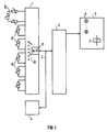
- the block diagram shows on the left the coupling of the input circuits via input circuit 1 and a comparison circuit 3 connected via a bus line 2, in the example implemented as a microcontroller, and a non-volatile memory 4, for example an E2 memory, which is connected via bus line 2 to the microcontroller and is connected to the input circuit 1.
- An output module 5 for triggering and / or reporting is connected to the microcontroller 3.
- Individual LEDs 6 and a trigger relay 7, which can be acted upon jointly or separately, are schematically indicated here.
- One or more temperature sensor circuits 8 can be provided, which can also consist of several individual temperature sensors 9, as was illustrated in the upper part of the input circuit 1.
- the individual temperature sensor circuits 8 are connected to an A / D converter 11 via a multiplexer 10, so that the resistance values of the individual temperature sensor circuits 8 can be fed to the microcontroller 3 via the bus 2 for processing.
- the resistance values of the temperature sensor circuits 8 are fed to the microcontroller 3 via the multiplexer 10 and the A / D converter 11 and the bus 2, and the change in time is evaluated here.
- the predetermined maximum change in the resistance values which results from the sensor characteristic and the machine properties and which are stored in the memory 4, are used for comparison. If the values determined exceed the maximum change, an intermittent takes place via the output module 5 Display via an LED 6. The position of the display indicates the defective sensor circuit.
- the change in resistance over time is first measured and then the change is compared when a predetermined maximum change in resistance is exceeded. If the comparison is negative, the program part is over. If the comparison is to be answered with yes, the wire break detection is initiated and, for example, an intermittent display is provided. To eliminate disturbances, several measurements and comparisons can be carried out in succession.
Landscapes
- Protection Of Static Devices (AREA)
- Gas-Insulated Switchgears (AREA)
- Control Of Multiple Motors (AREA)
- Testing Of Short-Circuits, Discontinuities, Leakage, Or Incorrect Line Connections (AREA)
- Measurement Of Resistance Or Impedance (AREA)
Claims (3)
- Dispositif de protection de machines électriques, ayant au moins un circuit à sonde de température, qui peut comporter une ou plusieurs sondes de température, pour le contrôle de températures inadmissibles des machines, et dans lequel les valeurs résistives des sondes de température sont exploitées dans un circuit d'exploitation et provoquent un déclenchement et/ou une signalisation, caractérisé par le fait que la variation dans le temps des valeurs résistives de la sonde de température (8, 9) sont comparées, dans un circuit comparateur (3), à un maximum de variation prescrit de la valeur résistive, donnée par la caractéristique de la sonde et par les caractéristiques de la machine et que, si ce maximum est dépassé, il se produit une signalisation particulière (6) et/ou un déclenchement particulier (7).
- Dispositif de protection suivant la revendication 1, caractérisé par le fait que la signalisation particulière (6) s'effectue pa la signalisation intermittente d'une diode à luminescence.
- Dispositif de protection suivant la revendication 2, caractérisé par le fait qu'il est prévu plusieurs cycles de mesure et de comparaison.
Priority Applications (4)
| Application Number | Priority Date | Filing Date | Title |
|---|---|---|---|
| AT90100927T ATE109317T1 (de) | 1990-01-17 | 1990-01-17 | Schutzeinrichtung für elektrische maschinen. |
| DE59006609T DE59006609D1 (de) | 1990-01-17 | 1990-01-17 | Schutzeinrichtung für elektrische Maschinen. |
| ES90100927T ES2057194T3 (es) | 1990-01-17 | 1990-01-17 | Instalacion de proteccion para maquinas electricas. |
| EP90100927A EP0437657B1 (fr) | 1990-01-17 | 1990-01-17 | Dispositif de protection pour une machine électrique |
Applications Claiming Priority (1)
| Application Number | Priority Date | Filing Date | Title |
|---|---|---|---|
| EP90100927A EP0437657B1 (fr) | 1990-01-17 | 1990-01-17 | Dispositif de protection pour une machine électrique |
Publications (2)
| Publication Number | Publication Date |
|---|---|
| EP0437657A1 EP0437657A1 (fr) | 1991-07-24 |
| EP0437657B1 true EP0437657B1 (fr) | 1994-07-27 |
Family
ID=8203507
Family Applications (1)
| Application Number | Title | Priority Date | Filing Date |
|---|---|---|---|
| EP90100927A Expired - Lifetime EP0437657B1 (fr) | 1990-01-17 | 1990-01-17 | Dispositif de protection pour une machine électrique |
Country Status (4)
| Country | Link |
|---|---|
| EP (1) | EP0437657B1 (fr) |
| AT (1) | ATE109317T1 (fr) |
| DE (1) | DE59006609D1 (fr) |
| ES (1) | ES2057194T3 (fr) |
Families Citing this family (1)
| Publication number | Priority date | Publication date | Assignee | Title |
|---|---|---|---|---|
| DE9310253U1 (de) * | 1993-07-09 | 1993-10-07 | "Elbag" Elektro-Schaltschrank- u. Gerätebau GmbH, 56348 Weisel | Vorrichtung zur Überwachung der Temperatur von Bauelementen und Geräten |
Family Cites Families (3)
| Publication number | Priority date | Publication date | Assignee | Title |
|---|---|---|---|---|
| US3280373A (en) * | 1962-09-06 | 1966-10-18 | Carrier Corp | Over-temperature protection system having means for simulating the temperature rise rate of a dynamoelectric machine and winding |
| DE1663122B1 (de) * | 1963-09-11 | 1970-11-05 | Siemens Ag | Schutzeinrichtung zur Temperaturueberwachung der Wicklungen von elektrischen Maschinen und Geraeten |
| US4377833A (en) * | 1981-08-17 | 1983-03-22 | Electric Power Research Institute, Inc. | Methods and apparatus for protecting electrical reactors |
-
1990
- 1990-01-17 EP EP90100927A patent/EP0437657B1/fr not_active Expired - Lifetime
- 1990-01-17 DE DE59006609T patent/DE59006609D1/de not_active Expired - Lifetime
- 1990-01-17 ES ES90100927T patent/ES2057194T3/es not_active Expired - Lifetime
- 1990-01-17 AT AT90100927T patent/ATE109317T1/de not_active IP Right Cessation
Also Published As
| Publication number | Publication date |
|---|---|
| ATE109317T1 (de) | 1994-08-15 |
| EP0437657A1 (fr) | 1991-07-24 |
| DE59006609D1 (de) | 1994-09-01 |
| ES2057194T3 (es) | 1994-10-16 |
Similar Documents
| Publication | Publication Date | Title |
|---|---|---|
| DE60119102T3 (de) | Elektronischer Schutzschalter | |
| DE112007001293B4 (de) | Energieversorgungssteuerung | |
| DE3114546C2 (fr) | ||
| DE3114551C2 (fr) | ||
| DE102011000897B4 (de) | Überstromschutzschaltung | |
| DE3933311C2 (fr) | ||
| DE4447145B4 (de) | Verfahren und Einrichtung zur Temperaturüberwachung bei Universalmotoren | |
| DE2502702A1 (de) | Detektor | |
| DE102016105517B3 (de) | Vorrichtung zur Überwachung mindestens zweier unterschiedlich langer LED-Ketten mit Hilfe programmierbarer Spannungsteiler | |
| DE102006029190B4 (de) | Überstrom-Erfassungsvorrichtung | |
| DE2204101B1 (de) | Feuermeldeanlage | |
| DE102012208115A1 (de) | Vorrichtung und Verfahren zur intelligenten Absicherung einer elektrischen Leitung | |
| EP0437657B1 (fr) | Dispositif de protection pour une machine électrique | |
| DE4119917A1 (de) | Ueberstromdetektoreinrichtung | |
| DE102021112934B4 (de) | Elektronische Stromverteileranordnung | |
| DE3027398C2 (de) | Elektrische Anzeigevorrichtung | |
| DE2723408C2 (de) | Vorrichtung zum Überlastungsschutz elektrischer Geräte | |
| DE3225106C2 (de) | Verfahren und Einrichtung zur automatischen Abfrage des Meldermeßwerts und der Melderkennung in einer Gefahrenmeldeanlage | |
| EP0678961B1 (fr) | Circuit reconnaissant et affichant l'interruption d'un conducteur | |
| EP0437658B1 (fr) | Dispositif de protection pour une machine électrique | |
| DE2027545A1 (de) | Schaltungsanordnung zur Erfassung einer Temperaturanderung | |
| DE3701070C2 (fr) | ||
| DE2162040C3 (de) | Schaltungsanordnung zum Erfassen von Leitungskurzschlussen | |
| DE3810157A1 (de) | Ueberwachung von elektrischen geraeten | |
| DE9310253U1 (de) | Vorrichtung zur Überwachung der Temperatur von Bauelementen und Geräten |
Legal Events
| Date | Code | Title | Description |
|---|---|---|---|
| PUAI | Public reference made under article 153(3) epc to a published international application that has entered the european phase |
Free format text: ORIGINAL CODE: 0009012 |
|
| 17P | Request for examination filed |
Effective date: 19901220 |
|
| AK | Designated contracting states |
Kind code of ref document: A1 Designated state(s): AT CH DE ES FR GB IT LI |
|
| 17Q | First examination report despatched |
Effective date: 19930603 |
|
| GRAA | (expected) grant |
Free format text: ORIGINAL CODE: 0009210 |
|
| AK | Designated contracting states |
Kind code of ref document: B1 Designated state(s): AT CH DE ES FR GB IT LI |
|
| REF | Corresponds to: |
Ref document number: 109317 Country of ref document: AT Date of ref document: 19940815 Kind code of ref document: T |
|
| REF | Corresponds to: |
Ref document number: 59006609 Country of ref document: DE Date of ref document: 19940901 |
|
| GBT | Gb: translation of ep patent filed (gb section 77(6)(a)/1977) |
Effective date: 19940908 |
|
| ITF | It: translation for a ep patent filed | ||
| REG | Reference to a national code |
Ref country code: ES Ref legal event code: FG2A Ref document number: 2057194 Country of ref document: ES Kind code of ref document: T3 |
|
| ET | Fr: translation filed | ||
| PLBE | No opposition filed within time limit |
Free format text: ORIGINAL CODE: 0009261 |
|
| STAA | Information on the status of an ep patent application or granted ep patent |
Free format text: STATUS: NO OPPOSITION FILED WITHIN TIME LIMIT |
|
| 26N | No opposition filed | ||
| REG | Reference to a national code |
Ref country code: GB Ref legal event code: IF02 |
|
| PGFP | Annual fee paid to national office [announced via postgrant information from national office to epo] |
Ref country code: CH Payment date: 20030408 Year of fee payment: 14 |
|
| PGFP | Annual fee paid to national office [announced via postgrant information from national office to epo] |
Ref country code: AT Payment date: 20031229 Year of fee payment: 15 |
|
| PGFP | Annual fee paid to national office [announced via postgrant information from national office to epo] |
Ref country code: ES Payment date: 20040114 Year of fee payment: 15 |
|
| PG25 | Lapsed in a contracting state [announced via postgrant information from national office to epo] |
Ref country code: LI Free format text: LAPSE BECAUSE OF NON-PAYMENT OF DUE FEES Effective date: 20040131 Ref country code: CH Free format text: LAPSE BECAUSE OF NON-PAYMENT OF DUE FEES Effective date: 20040131 |
|
| REG | Reference to a national code |
Ref country code: CH Ref legal event code: PL |
|
| PG25 | Lapsed in a contracting state [announced via postgrant information from national office to epo] |
Ref country code: AT Free format text: LAPSE BECAUSE OF NON-PAYMENT OF DUE FEES Effective date: 20050117 |
|
| PG25 | Lapsed in a contracting state [announced via postgrant information from national office to epo] |
Ref country code: ES Free format text: LAPSE BECAUSE OF NON-PAYMENT OF DUE FEES Effective date: 20050118 |
|
| REG | Reference to a national code |
Ref country code: ES Ref legal event code: FD2A Effective date: 20050118 |
|
| PGFP | Annual fee paid to national office [announced via postgrant information from national office to epo] |
Ref country code: GB Payment date: 20090116 Year of fee payment: 20 |
|
| PGFP | Annual fee paid to national office [announced via postgrant information from national office to epo] |
Ref country code: DE Payment date: 20090320 Year of fee payment: 20 Ref country code: IT Payment date: 20090127 Year of fee payment: 20 |
|
| PGFP | Annual fee paid to national office [announced via postgrant information from national office to epo] |
Ref country code: FR Payment date: 20090120 Year of fee payment: 20 |
|
| REG | Reference to a national code |
Ref country code: GB Ref legal event code: PE20 Expiry date: 20100116 |
|
| PG25 | Lapsed in a contracting state [announced via postgrant information from national office to epo] |
Ref country code: GB Free format text: LAPSE BECAUSE OF EXPIRATION OF PROTECTION Effective date: 20100116 |
|
| PG25 | Lapsed in a contracting state [announced via postgrant information from national office to epo] |
Ref country code: DE Free format text: LAPSE BECAUSE OF EXPIRATION OF PROTECTION Effective date: 20100117 |