EP0437700A2 - Installation pour l'alimentation en énergie d'une vitre chauffante à partir du réseau de bord du véhicule - Google Patents
Installation pour l'alimentation en énergie d'une vitre chauffante à partir du réseau de bord du véhicule Download PDFInfo
- Publication number
- EP0437700A2 EP0437700A2 EP19900122029 EP90122029A EP0437700A2 EP 0437700 A2 EP0437700 A2 EP 0437700A2 EP 19900122029 EP19900122029 EP 19900122029 EP 90122029 A EP90122029 A EP 90122029A EP 0437700 A2 EP0437700 A2 EP 0437700A2
- Authority
- EP
- European Patent Office
- Prior art keywords
- voltage
- resonant circuit
- heating
- electrical system
- vehicle electrical
- Prior art date
- Legal status (The legal status is an assumption and is not a legal conclusion. Google has not performed a legal analysis and makes no representation as to the accuracy of the status listed.)
- Granted
Links
Images


Classifications
-
- H—ELECTRICITY
- H05—ELECTRIC TECHNIQUES NOT OTHERWISE PROVIDED FOR
- H05B—ELECTRIC HEATING; ELECTRIC LIGHT SOURCES NOT OTHERWISE PROVIDED FOR; CIRCUIT ARRANGEMENTS FOR ELECTRIC LIGHT SOURCES, IN GENERAL
- H05B3/00—Ohmic-resistance heating
- H05B3/84—Heating arrangements specially adapted for transparent or reflecting areas, e.g. for demisting or de-icing windows, mirrors or vehicle windshields
-
- B—PERFORMING OPERATIONS; TRANSPORTING
- B60—VEHICLES IN GENERAL
- B60S—SERVICING, CLEANING, REPAIRING, SUPPORTING, LIFTING, OR MANOEUVRING OF VEHICLES, NOT OTHERWISE PROVIDED FOR
- B60S1/00—Cleaning of vehicles
- B60S1/02—Cleaning windscreens, windows or optical devices
- B60S1/023—Cleaning windscreens, windows or optical devices including defroster or demisting means
- B60S1/026—Cleaning windscreens, windows or optical devices including defroster or demisting means using electrical means
-
- H—ELECTRICITY
- H02—GENERATION; CONVERSION OR DISTRIBUTION OF ELECTRIC POWER
- H02M—APPARATUS FOR CONVERSION BETWEEN AC AND AC, BETWEEN AC AND DC, OR BETWEEN DC AND DC, AND FOR USE WITH MAINS OR SIMILAR POWER SUPPLY SYSTEMS; CONVERSION OF DC OR AC INPUT POWER INTO SURGE OUTPUT POWER; CONTROL OR REGULATION THEREOF
- H02M3/00—Conversion of DC power input into DC power output
- H02M3/22—Conversion of DC power input into DC power output with intermediate conversion into AC
- H02M3/24—Conversion of DC power input into DC power output with intermediate conversion into AC by static converters
- H02M3/28—Conversion of DC power input into DC power output with intermediate conversion into AC by static converters using discharge tubes with control electrode or semiconductor devices with control electrode to produce the intermediate AC
- H02M3/325—Conversion of DC power input into DC power output with intermediate conversion into AC by static converters using discharge tubes with control electrode or semiconductor devices with control electrode to produce the intermediate AC using devices of a triode or a transistor type requiring continuous application of a control signal
- H02M3/335—Conversion of DC power input into DC power output with intermediate conversion into AC by static converters using discharge tubes with control electrode or semiconductor devices with control electrode to produce the intermediate AC using devices of a triode or a transistor type requiring continuous application of a control signal using semiconductor devices only
- H02M3/337—Conversion of DC power input into DC power output with intermediate conversion into AC by static converters using discharge tubes with control electrode or semiconductor devices with control electrode to produce the intermediate AC using devices of a triode or a transistor type requiring continuous application of a control signal using semiconductor devices only in push-pull configuration
- H02M3/3372—Conversion of DC power input into DC power output with intermediate conversion into AC by static converters using discharge tubes with control electrode or semiconductor devices with control electrode to produce the intermediate AC using devices of a triode or a transistor type requiring continuous application of a control signal using semiconductor devices only in push-pull configuration of the parallel type
-
- H—ELECTRICITY
- H05—ELECTRIC TECHNIQUES NOT OTHERWISE PROVIDED FOR
- H05B—ELECTRIC HEATING; ELECTRIC LIGHT SOURCES NOT OTHERWISE PROVIDED FOR; CIRCUIT ARRANGEMENTS FOR ELECTRIC LIGHT SOURCES, IN GENERAL
- H05B1/00—Details of electric heating devices
- H05B1/02—Automatic switching arrangements specially adapted to apparatus ; Control of heating devices
- H05B1/0227—Applications
- H05B1/023—Industrial applications
- H05B1/0236—Industrial applications for vehicles
-
- B—PERFORMING OPERATIONS; TRANSPORTING
- B60—VEHICLES IN GENERAL
- B60R—VEHICLES, VEHICLE FITTINGS, OR VEHICLE PARTS, NOT OTHERWISE PROVIDED FOR
- B60R16/00—Electric or fluid circuits specially adapted for vehicles and not otherwise provided for; Arrangement of elements of electric or fluid circuits specially adapted for vehicles and not otherwise provided for
- B60R16/02—Electric or fluid circuits specially adapted for vehicles and not otherwise provided for; Arrangement of elements of electric or fluid circuits specially adapted for vehicles and not otherwise provided for electric constitutive elements
- B60R16/03—Electric or fluid circuits specially adapted for vehicles and not otherwise provided for; Arrangement of elements of electric or fluid circuits specially adapted for vehicles and not otherwise provided for electric constitutive elements for supply of electrical power to vehicle subsystems or for
-
- H—ELECTRICITY
- H05—ELECTRIC TECHNIQUES NOT OTHERWISE PROVIDED FOR
- H05B—ELECTRIC HEATING; ELECTRIC LIGHT SOURCES NOT OTHERWISE PROVIDED FOR; CIRCUIT ARRANGEMENTS FOR ELECTRIC LIGHT SOURCES, IN GENERAL
- H05B2203/00—Aspects relating to Ohmic resistive heating covered by group H05B3/00
- H05B2203/035—Electrical circuits used in resistive heating apparatus
Definitions
- the invention relates to a device for supplying energy to a heating disk from the vehicle electrical system according to the preamble of claim 1.
- a heating resistor for example a heatable windshield of a motor vehicle
- various options are known which lead to the highest possible heating output.
- a vehicle electrical system is known from DE-OS 37 43 316, in which, among other things, a heatable pane is also to be supplied with energy.
- a heatable pane is also to be supplied with energy.
- an AC voltage with a frequency of 50 Hz and a maximum voltage of 80 V is decoupled from the voltage intermediate circuit via a voltage converter and used for heating a pane.
- no information is given to assign a certain frequency to the heating voltage in such a way that, for example, interference protection regulations are reliably complied with.
- the generation of an AC voltage from a DC voltage using a resonant circuit is known from DE-OS 26 42 028.
- the DC voltage source is coupled to the load via an oscillating circuit, an electronic switching element, for example an on and off switchable conductor, being connected between the DC voltage source and the oscillating circuit.
- An inductance is connected in series with this semiconductor switching element.
- the device according to the invention for supplying energy to a heating disc from the vehicle electrical system has the advantage over the known disc heating systems that the supply of energy from the on-board electrical system is carried out in such a way that an alternating voltage of a specific frequency is applied to the heating disc, and this frequency can be selected so that on the one hand polarization effects in the disc can be avoided, and that the harmonic content of this voltage is as low as possible to comply with the existing interference protection regulations.
- the on-board electrical system voltage is also implemented with a high power output, i.e. down to the kilowatt range, with minimal power loss.
- FIG. 1 shows the principle of the resonance converter for a current-controlled parallel resonant circuit.
- 2 shows the same principle of the resonance converter for a voltage-controlled series resonant circuit
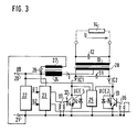
- FIG. 3 shows a detailed exemplary embodiment of a current-controlled parallel resonant circuit
- FIG. 4 shows a detailed exemplary embodiment of a voltage-controlled series resonant circuit.
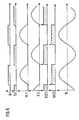
- FIG. 5 shows voltage and current profiles for the current-controlled parallel resonant circuit according to FIG. 3
- FIG. 6 shows voltage and current profiles for the voltage-controlled series resonant circuit according to FIG. 4.
- the same reference numerals have been used in the individual figures where it made sense.
- FIG. 1 shows the basic structure of a parallel resonant circuit with a current source 10, a switch 11 and the parallel resonant circuit consisting of a capacitor 12, a coil 13 and a resistor 14.
- the current source 10 is switched via the switch 11 in time with the resonance frequency of the resonant circuit 12, 13, 14 on the resonant circuit and therefore corresponds to a clocked current source, so that the resistor 14, which represents the consumer, that is, the heating disc, provided a sufficient Resonant circuit quality a sinusoidal voltage U is present with a low harmonic content.
- a voltage source 15 is applied to the series resonant circuit in a clocked manner via a power switch 11. This causes a rectangular voltage to be applied to the resonant circuit, which leads to a sinusoidal voltage U with a low harmonic content if the resonant circuit quality is sufficient at the resistor 14, which represents the heating disk.
- FIG. 3 shows an embodiment for a current-controlled parallel resonant circuit.
- the vehicle electrical system voltage + UB is at terminal 20, terminal 21 is at ground.
- the control electronics 22 and the base driver 23 are located between the terminals 20 and 21.
- the primary side coil 24 (choke), a protective circuit 25 and possibly the cathode of a diode 26, the anode of which is connected to ground via an auxiliary winding 27, are also connected to the terminal 20 is connected.
- the primary-side coil 24 is connected to the center tap of the primary winding of the transformer 28, the secondary winding of which represents the coil 13 or the inductance of the parallel resonant circuit, which also comprises a capacitor 12 and a resistor 14.
- the resistor 14 represents the load resistance, that is to say the heating disk, to which the harmonic-free voltage U is to be applied.
- the embodiment according to FIG. 3 has a capacitor 31, one side of which is connected to the power transistor 32 acting as a switch and the other side of which is connected to the power transistor 33 acting as a switch.
- a diode 34, 35 is located parallel to the collector-emitter path of the two transistors 32 and 33; the anodes of the two diodes are connected to the respective emitters and are grounded.
- transformer 36 Between the base of transistor 33 and ground is the secondary winding of a transformer 36, the primary winding of which is between ground and base driver 23.
- the secondary winding of a transformer 37 is connected to the base of the transistor 32.
- the primary-side coil (choke) 24 causes an impressed current I to be taken from the vehicle electrical system, which has the voltage UB, which current is supplied to the primary winding of the transformer 28, which is driven in push-pull, by means of the power transistors 32 and 33, which switch alternately.
- the transformer 28 is selected so that the required secondary voltage and thus the desired consumer power is set via its transmission ratio.
- the main inductance of the transformer 28 is used as an inductive component of the RLC parallel resonant circuit, corresponding to inductance 13 according to FIG. 1.
- the power transistors 32 and 33 which act as power switches, can be implemented as bipolar or MOS transistors, with the lowest possible forward voltage being the decisive selection criterion.
- the primary-side coil 24 must be connected to a demagnetizing auxiliary winding 27, a diode 26 being placed between the coil 24 and the auxiliary winding 27.
- the resonant circuit capacitor which bears the reference number 12 in accordance with the basic circuit shown in FIG. 1, can be attached on the primary side, secondary side or distributed to the primary and secondary side in the exemplary embodiment according to FIG.
- the capacitor 12 represents the secondary side and the capacitor 31 the primary side portion of the entire resonant circuit capacitor.
- the protection circuit 25 absorbs the energy stored in the transformer leakage inductance and is produced when the power transistors 32, 33 are switched off and is also used to reduce the current I flowing in the coil 24 when the device is switched off, provided that no control of the output power is provided and thus the diode 26 and the auxiliary winding 27 are not present. The shutdown energy absorbed can then be fed back into the main network.
- transistors 32 and 33 switch at zero voltage crossing so that minimal switching losses occur.
- the control electronics 22 supplies the alternating control signals U1 and U2, which are generated by a freely oscillating oscillator.
- the current flow angle of the two transistors 32 and 33 is 180 °, and when operating without a diode 26 and auxiliary winding 27, the control electronics 22 must ensure an overlap of the control signals during commutation.
- control of the output power from 0 to the maximum value can be achieved by specifying a current flow angle of less than 180 °.
- a negative voltage-time area of the magnitude UB x T out is applied to the coil 24 via the auxiliary winding 27 and the diode 26.
- the diodes 34 and 35 serve to absorb the inverse current which arises during the commutation of the transistors 32 and 33.
- MOS transistors these diodes are already present in the power component.
- U1 and U2 are two alternating square-wave voltages output by the control electronics 22. They either caused an almost rectangular current IC1 in transistor 32 or a likewise almost rectangular current IC2 in transistor 33. This creates collector-emitter voltages on the two transistors 32 and 33, which have the profile shown in FIG.
- the currents IC1 and IC2 cause the approximately sinusoidal voltage U to arise on the secondary side of the transformer 28, which voltage is ultimately used to supply the resistor 14, that is to say the disk heater.
- FIG. 4 shows the exemplary embodiment of a disk heater with a voltage-controlled series resonant circuit.
- the control electronics 22, the base driver 23, the protective circuit 25 and the transistors 32 and 33 with the associated diodes 34 and 35 and the two transmitters 36 and 37 are connected in the same way to the terminals 20 and 21 as in the exemplary embodiment according to FIG. 3.
- the terminal 20, at which the positive vehicle electrical system voltage UB is present, is connected directly to the center tap of the primary winding of the transformer 28.
- the secondary winding of the transformer 28 is connected via the series connection of an inductor or coil 38, a capacitor 12 and a resistor 14, which represents the heating disk, the secondary winding of the transformer 28 and the coil 38 forming the total inductance of the resonant circuit.
- the vehicle electrical system voltage UB is applied directly to the primary winding of the transformer 28 operated in push-pull mode via the alternating switching power transistors 32 and 33.
- the transmission ratio of the transformer 28 is designed such that the maximum output voltage U required to achieve the desired power is reached at the consumer.
- the function of the base driver 23 corresponds to the function of the base driver 23 according to FIG. 3.
- the protective circuit 25 absorbs the energy generated in the transformer leakage inductance during switching operations and leads it back in whole or in part back into the vehicle electrical system.
- the output power can be continuously adjusted between 0 and 180 ° by varying the switch-on ratio of the control signals U1 and U2 and thus the current flow angle of the power transistors 32 and 33.
- the coil 24 known from FIG. 3 which can be designed for high current loads, in this exemplary embodiment only one coil 13 (secondary choke) of small size is required.
- the transistors switch in the current zero crossing, so that minimal switching losses occur and therefore the circuit complexity for the base driver 23 can remain low.
- the collector current commutates to the respective opposite diode 34, 35, which then corresponds to an inverse diode.
- the control electronics 22 in turn supplies two antiphase voltage square-wave pulses U1 and U2, which are supplied to the base driver 23. As long as the voltage U1 has a value greater than 0, a collector current IC1 flows through the transistor 32 and causes a square-wave voltage UCE1. If, on the other hand, the voltage U2 is greater than or equal to 0, a pulsed current IC2 flows through the transistor 33 and causes a rectangular voltage UCE1.
- This is achieved by operating the transformer in push-pull mode to fully utilize the available on-board electrical system voltage and using power transistors with a low forward voltage, for example parallel connections of MOS transistors or bipolar transistors with a transformer-coupled base driver.
- the RLC resonant circuit When dimensioning the RLC resonant circuit, it should be noted that it is of such a quality that a sinusoidal voltage with a low harmonic content occurs at the consumer, i.e. at the heating disk, so that the existing interference protection regulations are met.
- the device according to the invention is usually used in vehicle electrical systems with a vehicle electrical system voltage UB of approximately 12 V.
- a voltage of approx. 20 - 100 V should be set so that the required heating power is generated.
- the frequency of the voltage applied to the disk can be selected in a relatively wide range, for example it can be a few kHz or, in order to get outside the listening range, for. B. 50 KHz.
- the level and frequency of the heating voltage can be adapted to requirements.
- the output power which is available in the resistor 14, that is to say the heating disk is correspondingly multiplied with almost the same losses.
Landscapes
- Engineering & Computer Science (AREA)
- Power Engineering (AREA)
- Mechanical Engineering (AREA)
- Electric Propulsion And Braking For Vehicles (AREA)
- Inverter Devices (AREA)
- Air-Conditioning For Vehicles (AREA)
- Dc-Dc Converters (AREA)
Applications Claiming Priority (2)
| Application Number | Priority Date | Filing Date | Title |
|---|---|---|---|
| DE3942593 | 1989-12-22 | ||
| DE3942593A DE3942593A1 (de) | 1989-12-22 | 1989-12-22 | Einrichtung zur energieversorgung einer heizscheibe aus dem fahrzeugbordnetz |
Publications (3)
| Publication Number | Publication Date |
|---|---|
| EP0437700A2 true EP0437700A2 (fr) | 1991-07-24 |
| EP0437700A3 EP0437700A3 (en) | 1991-11-13 |
| EP0437700B1 EP0437700B1 (fr) | 1994-03-02 |
Family
ID=6396217
Family Applications (1)
| Application Number | Title | Priority Date | Filing Date |
|---|---|---|---|
| EP90122029A Expired - Lifetime EP0437700B1 (fr) | 1989-12-22 | 1990-11-17 | Installation pour l'alimentation en énergie d'une vitre chauffante à partir du réseau de bord du véhicule |
Country Status (4)
| Country | Link |
|---|---|
| US (1) | US5170040A (fr) |
| EP (1) | EP0437700B1 (fr) |
| DE (2) | DE3942593A1 (fr) |
| ES (1) | ES2050912T3 (fr) |
Cited By (3)
| Publication number | Priority date | Publication date | Assignee | Title |
|---|---|---|---|---|
| GB2261333A (en) * | 1991-11-08 | 1993-05-12 | Gec Aerospace Ltd | Aircraft windshield heater system |
| WO2007015695A3 (fr) * | 2004-10-22 | 2007-03-29 | Ppg Ind Ohio Inc | Systeme desembuage/degivrage de pare-brise d'aeronef et son procede d'utilisation |
| DE102022204963A1 (de) | 2022-05-18 | 2023-11-23 | Vitesco Technologies GmbH | Verfahren und Vorrichtung zur Regelung der an eine elektrische Last abgegebenen elektrischen Leistung |
Families Citing this family (18)
| Publication number | Priority date | Publication date | Assignee | Title |
|---|---|---|---|---|
| US6218643B1 (en) * | 1991-07-18 | 2001-04-17 | Mitsubishi Denki Kabushiki Kaisha | Power supplying apparatus for automotive part |
| ES2071543B1 (es) * | 1992-10-19 | 1997-05-16 | Univ Oviedo | Sistema de control de convertidores resonantes mediante la variacion continua de la inductancia de dispersion variable. |
| ES2056747B1 (es) * | 1993-03-31 | 1997-10-16 | Alcatel Standard Electrica | Circuito de conversion de continua-continua. |
| US5375886A (en) * | 1993-04-14 | 1994-12-27 | Hosokawa Printing Co., Ltd. | Counterfeit-proof paper for discouraging attempt at reproduction with copying device |
| US5852284A (en) * | 1997-01-07 | 1998-12-22 | Libbey-Owens-Ford Co. | Insulating glass with capacitively coupled heating system |
| US6441352B1 (en) * | 2000-01-05 | 2002-08-27 | Ef Technologies, Inc. | Apparatus for electrically heat welding thermoplastic fittings and method of using the same |
| US6521868B1 (en) | 2001-11-02 | 2003-02-18 | Ford Global Technologies, Inc. | Method and apparatus for heating a portion of a vehicle |
| ITTO20030238A1 (it) * | 2003-03-28 | 2004-09-29 | Tetra Laval Holdings & Finance | Dispositivo e metodo di saldatura ad induzione utilizzabile |
| DE102004038011B3 (de) * | 2004-08-04 | 2006-05-11 | Webasto Ag | Glüheinrichtung für ein Fahrzeugzusatzheizgerät |
| US20060132045A1 (en) * | 2004-12-17 | 2006-06-22 | Baarman David W | Heating system and heater |
| US7968823B2 (en) * | 2006-06-07 | 2011-06-28 | Engineered Glass Products, Llc | Wireless inductive coupling assembly for a heated glass panel |
| US7696644B2 (en) * | 2007-02-06 | 2010-04-13 | Cooktek Llc | Wireless power transfer system for glass |
| ATE460824T1 (de) * | 2007-08-14 | 2010-03-15 | Tetra Laval Holdings & Finance | SELBSTKONFIGURIERENDE INDUKTIONSDICHTVORRICHTUNG ZUR VERWENDUNG BEI DER HERSTELLUNG VON VERPACKUNGEN FÜR AUSGIEßBARE LEBENSMITTELPRODUKTE |
| US8344296B2 (en) * | 2007-10-10 | 2013-01-01 | Cooktek Induction Systems, Llc | Food warming device and system |
| DE102008037242B4 (de) | 2008-08-09 | 2022-05-19 | Bayerische Motoren Werke Aktiengesellschaft | Fahrzeugenergiebordnetz |
| US8225704B2 (en) * | 2010-01-16 | 2012-07-24 | Nanoridge Materials, Inc. | Armor with transformed nanotube material |
| JPWO2013038694A1 (ja) * | 2011-09-14 | 2015-03-23 | パナソニックIpマネジメント株式会社 | 非接触受電装置および非接触電力伝送装置 |
| DE102020212683B4 (de) | 2020-07-15 | 2022-03-10 | Vitesco Technologies GmbH | Verfahren zum Regeln eines Generators eines Automobilstromversorgungsnetzes |
Family Cites Families (10)
| Publication number | Priority date | Publication date | Assignee | Title |
|---|---|---|---|---|
| US3899730A (en) * | 1970-12-12 | 1975-08-12 | Alfa Romeo Spa | Method of eliminating risk of discharge of a battery in an electrical installation for a motor vehicle and an apparatus for effecting the same |
| US3887781A (en) * | 1971-04-06 | 1975-06-03 | Environment One Corp | Metal base cookware induction heating apparatus having improved control circuit using infra-red temperature sensor |
| JPS5324965B1 (fr) * | 1971-07-31 | 1978-07-24 | ||
| DE2642028C2 (de) * | 1976-09-18 | 1986-01-09 | Flender-Himmelwerk GmbH & Co KG, 7400 Tübingen | Selbsterregter statischer Wechselstromgenerator |
| US4277672A (en) * | 1979-12-03 | 1981-07-07 | General Electric Company | Control circuit for controlling quantity of heat to electrically heatable windshield |
| US4357524A (en) * | 1980-01-29 | 1982-11-02 | Westinghouse Electric Corp. | Electrical heater controller for aircraft window heat control |
| US4434358A (en) * | 1980-02-13 | 1984-02-28 | Westinghouse Electric Corp. | Aircraft window heat controller with switched impedances |
| US4620084A (en) * | 1983-12-27 | 1986-10-28 | Gen Electric | Aircraft thermostat |
| DE3743316A1 (de) * | 1987-12-21 | 1989-06-29 | Bosch Gmbh Robert | Fahrzeugbordnetzsystem |
| FR2646049B1 (fr) * | 1989-04-18 | 1991-05-24 | Cableco Sa | Plaque electrique chauffante amovible |
-
1989
- 1989-12-22 DE DE3942593A patent/DE3942593A1/de not_active Withdrawn
-
1990
- 1990-10-26 US US07/605,116 patent/US5170040A/en not_active Expired - Lifetime
- 1990-11-17 DE DE90122029T patent/DE59004786D1/de not_active Expired - Fee Related
- 1990-11-17 ES ES90122029T patent/ES2050912T3/es not_active Expired - Lifetime
- 1990-11-17 EP EP90122029A patent/EP0437700B1/fr not_active Expired - Lifetime
Cited By (6)
| Publication number | Priority date | Publication date | Assignee | Title |
|---|---|---|---|---|
| GB2261333A (en) * | 1991-11-08 | 1993-05-12 | Gec Aerospace Ltd | Aircraft windshield heater system |
| WO2007015695A3 (fr) * | 2004-10-22 | 2007-03-29 | Ppg Ind Ohio Inc | Systeme desembuage/degivrage de pare-brise d'aeronef et son procede d'utilisation |
| JP2008516849A (ja) * | 2004-10-22 | 2008-05-22 | ピーピージー インダストリーズ オハイオ, インコーポレイテッド | 航空機の風防をデフォギング/デアイシングするシステムおよびその使用方法 |
| CN100542887C (zh) * | 2004-10-22 | 2009-09-23 | Ppg工业俄亥俄公司 | 航空器风挡去雾/去冰系统及其使用方法 |
| US7928345B2 (en) | 2004-10-22 | 2011-04-19 | Ppg Industries Ohio, Inc. | Aircraft windshield defogging/deicing system and method of use thereof |
| DE102022204963A1 (de) | 2022-05-18 | 2023-11-23 | Vitesco Technologies GmbH | Verfahren und Vorrichtung zur Regelung der an eine elektrische Last abgegebenen elektrischen Leistung |
Also Published As
| Publication number | Publication date |
|---|---|
| US5170040A (en) | 1992-12-08 |
| EP0437700B1 (fr) | 1994-03-02 |
| EP0437700A3 (en) | 1991-11-13 |
| DE59004786D1 (de) | 1994-04-07 |
| ES2050912T3 (es) | 1994-06-01 |
| DE3942593A1 (de) | 1991-06-27 |
Similar Documents
| Publication | Publication Date | Title |
|---|---|---|
| EP0437700B1 (fr) | Installation pour l'alimentation en énergie d'une vitre chauffante à partir du réseau de bord du véhicule | |
| DE69009359T2 (de) | Leistungsquellevorrichtung. | |
| DE2461440C2 (de) | Schaltungsanordnung zum Betreiben einer einphasigen Wechsel- oder Gleichstromlast | |
| DE2423718B2 (de) | Schaltungsanordnung zur erzeugung einer wechselspannung | |
| DE2756799A1 (de) | Impulsgesteuertes stromversorgungsgeraet | |
| DE1463876A1 (de) | Starkstrom-Zerhackerschaltung mit Festkoerper-Bauelementen | |
| EP0231481A2 (fr) | Convertisseur courant alternatif - courant continu avec circuit en demi-pont asymétrique | |
| DE2658903A1 (de) | Schalt-spannungsregler | |
| EP0096778B1 (fr) | Microphone | |
| EP0696102B1 (fr) | Convertisseur direct avec une circuit de sortie auxiliaire | |
| EP0247409B1 (fr) | Alimentation à commutation avec convertisseur à courant continu à découpage sur le primaire | |
| EP0025234B1 (fr) | Amplificateur de puissance basse fréquence et application à un émetteur à modulation d'amplitude | |
| DE3508289C1 (de) | Wechselrichter zur Speisung eines Verbrauchers mit einer induktiven Komponente | |
| EP0050753A1 (fr) | Disposition de circuit pour alimenter un utilisateur en courant alternatif avec une tension alternative et plus particulièrement avec une tension sinusoidale | |
| DE3244988A1 (de) | Gegentakt-wechselrichterschaltung mit gespeicherter ladung fuer schnelles umschalten | |
| EP0270920B1 (fr) | Procédé et dispositif de production de signaux de courant d'émission dans un réseau de distribution d'énergie à courant alternatif | |
| DE3333656A1 (de) | Wechselspannungsumsetzer | |
| AT399625B (de) | Bidirektionale wandlerschaltung | |
| DE2634193A1 (de) | Getaktetes netzgeraet | |
| DE4430078A1 (de) | Schaltungsanordnung zur Vermeidung von Schaltverlusten eines Zweigpaares eines selbstgeführten Stromrichters mit eingeprägter Zwischenkreisgleichspannung | |
| EP0263936B1 (fr) | Alimentation de puissance à commutation sur le circuit secondaire | |
| DE102021103205A1 (de) | Zuführen von elektrischer Energie von einem Wechselspannungsnetz zu einem Gleichspannungsnetz | |
| DE3418657A1 (de) | Anordnung zur steuerung von abschaltthyristoren hoeherer leistung | |
| EP0211210A1 (fr) | Amplificateur à commutation | |
| DE102023208316A1 (de) | Resonanter DC-Steller und Verfahren zum Betreiben eines resonanten DC-Stellers |
Legal Events
| Date | Code | Title | Description |
|---|---|---|---|
| PUAI | Public reference made under article 153(3) epc to a published international application that has entered the european phase |
Free format text: ORIGINAL CODE: 0009012 |
|
| AK | Designated contracting states |
Kind code of ref document: A2 Designated state(s): DE ES FR GB |
|
| PUAL | Search report despatched |
Free format text: ORIGINAL CODE: 0009013 |
|
| AK | Designated contracting states |
Kind code of ref document: A3 Designated state(s): DE ES FR GB |
|
| RAP3 | Party data changed (applicant data changed or rights of an application transferred) |
Owner name: ROBERT BOSCH GMBH |
|
| 17P | Request for examination filed |
Effective date: 19920414 |
|
| 17Q | First examination report despatched |
Effective date: 19920922 |
|
| GRAA | (expected) grant |
Free format text: ORIGINAL CODE: 0009210 |
|
| AK | Designated contracting states |
Kind code of ref document: B1 Designated state(s): DE ES FR GB |
|
| GBT | Gb: translation of ep patent filed (gb section 77(6)(a)/1977) |
Effective date: 19940228 |
|
| ET | Fr: translation filed | ||
| REF | Corresponds to: |
Ref document number: 59004786 Country of ref document: DE Date of ref document: 19940407 |
|
| REG | Reference to a national code |
Ref country code: ES Ref legal event code: FG2A Ref document number: 2050912 Country of ref document: ES Kind code of ref document: T3 |
|
| REG | Reference to a national code |
Ref country code: GB Ref legal event code: 746 Effective date: 19941007 |
|
| PLBE | No opposition filed within time limit |
Free format text: ORIGINAL CODE: 0009261 |
|
| STAA | Information on the status of an ep patent application or granted ep patent |
Free format text: STATUS: NO OPPOSITION FILED WITHIN TIME LIMIT |
|
| 26N | No opposition filed | ||
| PGFP | Annual fee paid to national office [announced via postgrant information from national office to epo] |
Ref country code: GB Payment date: 19991111 Year of fee payment: 10 |
|
| PGFP | Annual fee paid to national office [announced via postgrant information from national office to epo] |
Ref country code: ES Payment date: 19991118 Year of fee payment: 10 |
|
| PGFP | Annual fee paid to national office [announced via postgrant information from national office to epo] |
Ref country code: FR Payment date: 19991123 Year of fee payment: 10 |
|
| PG25 | Lapsed in a contracting state [announced via postgrant information from national office to epo] |
Ref country code: GB Free format text: LAPSE BECAUSE OF NON-PAYMENT OF DUE FEES Effective date: 20001117 |
|
| PG25 | Lapsed in a contracting state [announced via postgrant information from national office to epo] |
Ref country code: ES Free format text: LAPSE BECAUSE OF NON-PAYMENT OF DUE FEES Effective date: 20001118 |
|
| GBPC | Gb: european patent ceased through non-payment of renewal fee |
Effective date: 20001117 |
|
| PG25 | Lapsed in a contracting state [announced via postgrant information from national office to epo] |
Ref country code: FR Free format text: LAPSE BECAUSE OF NON-PAYMENT OF DUE FEES Effective date: 20010731 |
|
| REG | Reference to a national code |
Ref country code: FR Ref legal event code: ST |
|
| REG | Reference to a national code |
Ref country code: ES Ref legal event code: FD2A Effective date: 20011214 |
|
| PGFP | Annual fee paid to national office [announced via postgrant information from national office to epo] |
Ref country code: DE Payment date: 20060127 Year of fee payment: 16 |
|
| PG25 | Lapsed in a contracting state [announced via postgrant information from national office to epo] |
Ref country code: DE Free format text: LAPSE BECAUSE OF NON-PAYMENT OF DUE FEES Effective date: 20070601 |