EP0437717B1 - Soupape à siège - Google Patents
Soupape à siège Download PDFInfo
- Publication number
- EP0437717B1 EP0437717B1 EP90123224A EP90123224A EP0437717B1 EP 0437717 B1 EP0437717 B1 EP 0437717B1 EP 90123224 A EP90123224 A EP 90123224A EP 90123224 A EP90123224 A EP 90123224A EP 0437717 B1 EP0437717 B1 EP 0437717B1
- Authority
- EP
- European Patent Office
- Prior art keywords
- valve
- seat
- pressure
- spring
- chamber
- Prior art date
- Legal status (The legal status is an assumption and is not a legal conclusion. Google has not performed a legal analysis and makes no representation as to the accuracy of the status listed.)
- Expired - Lifetime
Links
- 230000035939 shock Effects 0.000 claims description 12
- 239000007788 liquid Substances 0.000 claims description 6
- 230000007935 neutral effect Effects 0.000 claims description 3
- 239000000463 material Substances 0.000 claims description 2
- 230000014759 maintenance of location Effects 0.000 claims 4
- 238000012423 maintenance Methods 0.000 abstract 1
- 230000000694 effects Effects 0.000 description 13
- 230000000903 blocking effect Effects 0.000 description 3
- 238000010276 construction Methods 0.000 description 3
- 238000009825 accumulation Methods 0.000 description 2
- 230000008030 elimination Effects 0.000 description 2
- 238000003379 elimination reaction Methods 0.000 description 2
- 230000000717 retained effect Effects 0.000 description 2
- 230000004888 barrier function Effects 0.000 description 1
- 238000010586 diagram Methods 0.000 description 1
- 238000005516 engineering process Methods 0.000 description 1
- 230000007717 exclusion Effects 0.000 description 1
- 230000005226 mechanical processes and functions Effects 0.000 description 1
- 230000036316 preload Effects 0.000 description 1
- 230000001105 regulatory effect Effects 0.000 description 1
- XLYOFNOQVPJJNP-UHFFFAOYSA-N water Substances O XLYOFNOQVPJJNP-UHFFFAOYSA-N 0.000 description 1
Images


Classifications
-
- F—MECHANICAL ENGINEERING; LIGHTING; HEATING; WEAPONS; BLASTING
- F15—FLUID-PRESSURE ACTUATORS; HYDRAULICS OR PNEUMATICS IN GENERAL
- F15B—SYSTEMS ACTING BY MEANS OF FLUIDS IN GENERAL; FLUID-PRESSURE ACTUATORS, e.g. SERVOMOTORS; DETAILS OF FLUID-PRESSURE SYSTEMS, NOT OTHERWISE PROVIDED FOR
- F15B11/00—Servomotor systems without provision for follow-up action; Circuits therefor
- F15B11/003—Systems with load-holding valves
-
- F—MECHANICAL ENGINEERING; LIGHTING; HEATING; WEAPONS; BLASTING
- F15—FLUID-PRESSURE ACTUATORS; HYDRAULICS OR PNEUMATICS IN GENERAL
- F15B—SYSTEMS ACTING BY MEANS OF FLUIDS IN GENERAL; FLUID-PRESSURE ACTUATORS, e.g. SERVOMOTORS; DETAILS OF FLUID-PRESSURE SYSTEMS, NOT OTHERWISE PROVIDED FOR
- F15B13/00—Details of servomotor systems ; Valves for servomotor systems
- F15B13/01—Locking-valves or other detent i.e. load-holding devices
-
- F—MECHANICAL ENGINEERING; LIGHTING; HEATING; WEAPONS; BLASTING
- F15—FLUID-PRESSURE ACTUATORS; HYDRAULICS OR PNEUMATICS IN GENERAL
- F15B—SYSTEMS ACTING BY MEANS OF FLUIDS IN GENERAL; FLUID-PRESSURE ACTUATORS, e.g. SERVOMOTORS; DETAILS OF FLUID-PRESSURE SYSTEMS, NOT OTHERWISE PROVIDED FOR
- F15B2211/00—Circuits for servomotor systems
- F15B2211/50—Pressure control
- F15B2211/505—Pressure control characterised by the type of pressure control means
- F15B2211/50509—Pressure control characterised by the type of pressure control means the pressure control means controlling a pressure upstream of the pressure control means
- F15B2211/50545—Pressure control characterised by the type of pressure control means the pressure control means controlling a pressure upstream of the pressure control means using braking valves to maintain a back pressure
Definitions
- the invention relates to a seat valve of the type specified in the preamble of claim 1.
- Such seat valves are known in practice by the types MV, MVS, MVE, MVP and DMV, assembly 4, from Heilmeier & Weinlein, 8 Kunststoff 80, which have been sold for years. They are used as a pressure relief valve, as a safety valve, as a pressure reducing valve and the like.
- the pressure to be regulated is present in the first pressure medium channel, while the second pressure medium channel leads, for example, to a tank line. With the setting of the preload of the spring, the pressure limit is determined at which the valve member lifts off the valve seat and allows pressure medium to flow out. If the second pressure medium channel is depressurized or almost depressurized, the seat valve responds properly.
- an elimination device for the spring closing pressure is provided, which suddenly removes the spring closing pressure when the valve member is lifted from the valve seat, so that the valve member reaches a second seat and the connection is closed cordoned off a relief line.
- the elimination device is ineffective because its piston is exposed to the pressure in the relief line on both sides.
- a pressure increase in the relief line adds up to the spring closing pressure when the valve member rests on the valve seat.
- the closing spring presses the valve member together with the load pressure onto the valve seat.
- a pressure compensation piston in a control chamber facing away from the closing spring is loaded in the opening direction of the valve member on a loading surface with the load pressure which is equal to the loading surface of the valve member exposed to the load pressure in the closing direction. In this way, the load pressure is compensated without affecting the closing force of the closing spring.
- the control force remains constant regardless of fluctuations in load pressure.
- the check valve does not respond to a set limit of the load pressure.
- a pressure increase in the Drain line acts on the valve member in the opening direction and changes the closing force.
- the invention has for its object to improve a seat valve of the type mentioned so that the addition effect is avoided.
- the effect of the pressure prevailing in the second pressure medium channel on the valve member pressed onto the valve seat cannot be avoided.
- the hydraulic closing force on the valve member which increases with increasing pressure, is compensated for or largely compensated for by the relief of the spring in such a way that the addition effect does not occur.
- the poppet valve responds independently or almost independently of the pressure in the second pressure medium channel.
- the structure of the seat valve remains simple and inexpensive because essentially all the components that have been customary to date are used. Only the reducing device that can be easily integrated into the seat valve is added. The range of possible uses of such seat valves is advantageously increased.
- a lowering brake check valve with the type designation 1 EXP 65 83 in which the influence of a variable pressure in the second pressure medium channel on the opening behavior of the valve is thereby eliminated is that the valve member as a complicated, large-scale and processing technology sophisticated differential sleeve piston is formed, which is used in a complex and large housing so that it is pressure balanced.
- Such complex valves are particularly useful for large flow rates because of their size. These valves cannot be compared to simple, small seat valves.
- the influence of the variable pressure in the second pressure medium channel is achieved by a special construction of the valve member and the housing without involving the spring.
- the piston can be accommodated with little structural effort in such a way that it automatically and mechanically relieves the spring, depending on the pressure prevailing in the second pressure medium channel, as the pressure presses the valve member onto the valve seat. In this way, the variable pressure in the second pressure medium channel increasingly takes over the function of the spring, which is at least largely released from this function by the reducing device at the same time.
- the embodiment of claim 3 is expedient because the piston relieves the spring to the same extent as the pressure presses the valve member onto the valve seat.
- the seat valve always works as if the second pressure medium channel were depressurized.
- the embodiment according to claim 4 can also be appropriate, because with this undersize of the piston, a residual force of the spring remains effective, which ensures the mechanical function of the seat valve. This measure is also important for a flawless Guiding and holding the valve member, which could otherwise carry out undesired own movements if the spring is quickly tensioned when the pressure in the second pressure medium channel increases.
- a further, particularly expedient embodiment emerges from claim 5.
- the piston relieves the spring via the pull rod, which is attached to the spring abutment that engages the valve member.
- the embodiment according to claim 6 is also structurally simple and streamlined because the piston is located away from the direct working area of the valve member and does not impair the flow.
- the liquid barrier element ensures that water or other harmful media do not enter the cylinder chamber from the outside environment and impair the function of the piston.
- the liquid blocking element can be arranged in the cylinder chamber, between the cylinder chamber and the external environment in the housing of the seat valve or on the outer side of the housing of the seat valve. If the liquid blocking element is a porous insert, e.g. made of sintered material, then the air can pass freely in both directions, while liquid or other harmful media are retained.
- a further advantageous embodiment with axial flow through the seat valve results from claim 9 forth.
- the basic concept of already proven seat valves is retained. Only the insert needs to be structurally adapted and the piston attached to the pull rod.
- the embodiment of claim 10 is advantageous because the seat valve here, in its function as a load-holding valve, meets the requirements which, on the one hand, concern the flow in both directions and, on the other hand, the exclusion of an accumulation effect.
- the reduction of pressure surges on the part of the consumer is of particular importance.
- the shock valve is provided for this purpose. However, it is necessary for the load holding valve to allow the pressure to be reduced to reach the shock valve without the accumulation effect. If a pressure surge occurs, then because of the reducing device for the spring of the valve member, the poppet valve responds at the set pressure limit and allows the pressure to the shock valve, regardless of how high the pressure in the second pressure medium channel is.
- the pressure medium between the seat valve and the slide control valve could not flow out, so that the valve member would remain closed with high force.
- the reducing device ensures, however, that the seat valve responds properly and the shock valve can reduce the pressure surge.
- a seat valve S of a conventional generic type according to FIG. 1 contains a valve seat O in a housing (not shown in more detail), onto which a valve member V is pressed by a spring C.
- a first pressure medium channel K1 which carries the pressure P, leads to the valve seat O.
- the spring C is arranged in a housing chamber R, to which a second pressure medium channel K2 is connected, which has a pressure p.
- a third pressure medium channel K3 branches off from the chamber R to a safety or shock valve B, which has a response pressure P ', which is, for example, greater than the normal pressure P.
- the valve seat O has a cross-sectional area f which corresponds to the area , on which the pressures P and p act in opposite directions on the valve member V.
- the pressure value of P is determined by f and the force of the spring C, i.e. the pressure limit at which the seat valve S responds. If the pressure p is equal to zero, the valve member V is lifted off when the pressure P is reached. The pressure P remains limited to a value which corresponds to the force of the spring C. However, if for some reason p increases to a value greater than zero, this pressure acts on the surface f of the valve member in the closing direction in addition to the force of the spring C. This means that the poppet valve no longer responds at the set pressure P, but only at one higher pressure. This addition effect is not practical if P has to be observed.
- the shock valve B is used, for example, to reduce a pressure surge in the pressure medium channel K2.
- the pressure surge is only properly degraded if p is zero.
- the valve member V lifts off at the pressure P and allows the shock valve to respond in a predetermined manner.
- the pressure p is greater than zero for some reason, the valve member V does not lift off from the valve seat O at the pressure P, but only at a possibly higher pressure.
- the shock valve B does not respond in the predetermined manner.
- the seat valve S1 contains a relief device E for the spring C which acts on the valve member V.
- the relief device E consists of a piston T with an action surface f 'which corresponds to or only slightly deviates from the action surface of the valve member V.
- the piston T is arranged between the valve member V and the spring C, the spring C sitting in a secondary chamber R ', which is relieved of the atmosphere A.
- the surface f 'of the piston T is expediently equal to the surface f of the valve member V or the valve seat O, so that the pressure p cannot have a disruptive effect.
- the acting area of the piston T can be smaller than the acting area f of the valve member V, e.g. at 10%.
- the seat valve S1 is integrated as a load holding valve LHV in a hydraulic control device.
- the control device contains a schematically indicated slide control valve D, preferably with the neutral position closed.
- the shock valve B indicated in Fig. 2 is incorporated into the slide control valve D so that it can establish a connection to the return.
- the slide control valve D is used to control a consumer Z, here for example a double-acting hydraulic cylinder, which has to move a load L.
- Two lines Z1 and Z2 connect the consumer Z to the slide control valve D.
- the poppet valve S1 is arranged such that the consumer Z is connected to the valve seat O via the line Z1, while the slide control valve D is connected to the chamber R. is.
- the relief device E is contained in the seat valve S1. Furthermore, the seat valve S1 with a check valve G, expediently one Platelet check valve, which enables an unimpeded flow in the direction from the slide control valve D to the consumer Z. Furthermore, a hydraulic unlocking device F is provided for the seat valve S1, which acts on the valve member through the valve seat O and is acted upon by a pilot line H, which is connected to the line Z2.
- the load L is held by the seat valve S1 up to a set pressure. If a pressure surge occurs, for example because the load L generates an additional force in the direction of the arrow, the excess pressure is reduced via the shock valve B.
- pressure is built up in the line Z2 via the slide control valve D, which lifts the valve member V from the valve seat O via the auxiliary control line H and the unlocking device F so that a certain movement speed is maintained.
- the check valve G opens; the unlocking device F need not come into effect for this.
- FIG. 4 shows a more specific embodiment of the seat valve S1, again using the same reference numerals as in FIG. 2 for the corresponding elements.
- the seat valve S1 has a sleeve-shaped housing 1 with an inner bore into which an insert 2 is screwed, which contains the second pressure medium channel K2 as an axial bore. Furthermore, a central bore 3 is made in the insert 2, which is closed at one end by a plug 4. From the Bore 3 leads a relief port 5 to the atmosphere, which is closed by a liquid blocking element 6. Furthermore, a rear spring abutment 7 is screwed into the housing 1, which supports the end 20 of the spring C, which is averted from the valve member V, here a helical spring 21, and allows the pretension to be changed. The other end 19 of the spring C is seated on a spring abutment 8, which stands on the valve member V designed as a ball 11. The spring abutment 8 is connected to a tie rod 9 which projects into the bore 3 and carries the piston T, 10 there. The piston T, 10 is sealed and displaceable in the bore 3, which defines a cylinder space 22 which is open to the chamber R.
- a further housing part 12 is screwed, which contains the valve seat O designed as an insert 13.
- the check valve G arranged there is a plate valve, consisting of an annular disk-shaped plate 14 and through channels 15 in use 13.
- the unlocking device F is also housed, which has a piston 24 and a plunger 23, which through the valve seat O directly on the valve seat V attacks.
- the check valve G opens in the direction of flow from the pressure medium channel K2 to the pressure medium channel K1; the pressure medium flows through relatively unthrottled. In the opposite direction, ie in the flow direction from the pressure medium channel K1 to the pressure medium channel K2, the check valve G. closes.
- the pressure from the pressure medium channel K1 must lift the valve member V from the valve seat O against the force of the spring C, whereby it is determined by the force of the spring C. Must reach pressure level if the unlocking device F is not is operated.
- the unlocking device F opens the valve V, O, then pressure medium flows out to the extent that this is brought about by the actuation of the piston 24.
- the piston in each case is pressurized in the chamber R. Via the pull rod 9 and the spring abutment 8, it relieves the valve member V of the spring C to the extent that the pressure in the chamber R increases.
- the insert 13 is here somewhat larger than in FIG. 4.
- the cylinder 17 with the orifice openings 18 leads to an improved control behavior of the seat valve S1.
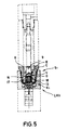
- the seat valve S1 corresponds to the seat valve S1 of Fig. 4, i.e. the pull rod 9 carries a piston acted upon by the pressure in the chamber R against the force of the spring C, the other side of which is relieved of the atmosphere.
Landscapes
- Engineering & Computer Science (AREA)
- Physics & Mathematics (AREA)
- Fluid Mechanics (AREA)
- Mechanical Engineering (AREA)
- General Engineering & Computer Science (AREA)
- Safety Valves (AREA)
- Compressor (AREA)
- External Artificial Organs (AREA)
Claims (10)
- Soupape à siège (S1), soupape de maintien de charge notamment, avec un organe de soupape (V) qui peut être pressé par un ressort (C), dans une chambre de cage (R), contre un siège de soupape (O) circulaire, disposé dans une paroi de la chambre, avec un premier conduit de fluide sous pression (K1), raccordé au siège de soupape (O), et avec un deuxième conduit de fluide sous pression (K2), raccordé à la chambre (R), ces deux conduits étant séparés l'un de l'autre par le siège de soupape (O), et l'organe de soupape (V) pouvant être totalement sollicité, dans les deux sens opposés, par les pressions régnant dans les conduits de fluide sous pression (K1, K2) sur une surface (f), définie par le diamètre du siège de soupape (O), caractérisée en ce qu'un dispositif de réduction (E) est prévu dans la chambre (R) pour la pression de fermeture du ressort de l'organe de soupape (V), ce dispositif pouvant être actionné, lorsque l'organe de soupape (V) est pressé sur le siège de soupape (O), par la pression régnant dans le deuxième conduit de fluide sous pression (K2) et dans la chambre (R), et permettant à peu près de réduire la pression de fermeture du ressort de la valeur dont cette pression, sur la surface (f) de l'organe de soupape (V), presse ce dernier sur le siège de soupape (O).
- Soupape à siège suivant la revendication 1, caractérisée en ce qu'une extrémité (19) du ressort (C), sollicitant l'organe de soupape (V), est couplée mécaniquement à un piston (T, 10), mobile et étanche dans le sens d'ouverture et/ou de fermeture de l'organe de soupape, ce piston étant sollicité par la pression régnant dans le deuxième conduit de fluide sous pression (K2), dans le sens d'ouverture de l'organe de soupape (V), et par la pression atmosphérique, dans le sens de fermeture de l'organe de soupape (V).
- Soupape à siège suivant la revendication 2, caractérisée en ce que la surface de sollicitation du piston est égale à la surface de sollicitation (f) de l'organe de soupape (V) sur le siège de soupape (O).
- Soupape à siège suivant la revendication 2, caractérisée en ce que la surface de sollicitation du piston est inférieure à la surface de sollicitation (f) de l'organe de soupape (V), de 10% environ de préférence.
- Soupape à siège suivant la revendication 2, caractérisée en ce que le piston est monté sur une barre de traction (9), disposée à l'intérieur du ressort (C), réalisé sous forme de ressort hélicoïdal (21), et en ce que la barre de traction (9) est reliée à une butée de ressort (8), s'appliquant sur l'organe de soupape (V), pour l'une des extrémités du ressort (19) sollicitant l'organe de soupape (V).
- Soupape à siège suivant l'une quelconque des revendications 1 à 5, caractérisée en ce que la barre de traction (9) traverse une butée de ressort (7) disposée dans la chambre (R), pour l'autre extrémité du ressort (20), et pénètre dans un compartiment de cylindre (22) ouvert sur la chambre (R), dans lequel se déplace le piston, de manière étanche, et est détendu à l'atmosphère, à l'opposé de la chambre (R).
- Soupape à siège suivant l'une quelconque des revendications 1 à 6, caractérisée en ce que l'organce de soupape est sphérique ou conique.
- Soupape à siège suivant la revendication 6, caractérisée en ce qu'un conduit de détente (5) du compartiment de cylindre (22) est fermé par un élément de barrage du liquide (6) perméable à l'air, par un joint torique souple de préférence avec une fonction antiretour, ou par une garniture poreuse, en matériau fritté par exemple.
- Soupape à siège suivant la revendication 6, caractérisée en ce que l'un des conduits de fluide sous pression (K2) est disposé dans une garniture (2), délimitant la chambre (R), et en ce que le compartiment de cylindre (22) est formé, dans cette garniture (2), par un trou de passage (3) fermé par un bouchon (4) sur l'extrémité opposée à la chambre (R).
- Soupape à siège suivant l'une quelconque des revendications 1 à 9, caractérisée en ce que la soupape à siège (S1) est réalisée sous forme de soupape de maintien de charge (LHV), balayée par le fluide par l'intermédiaire du siège de soupape (O) dans le sens d'écoulement du premier conduit (K1) en direction du deuxième conduit de fluide sous pression (K2), et par l'intermédiaire d'un clapet antiretour parallèle (G) dans le sens d'écoulement opposé, avec un dispositif de déverrouillage (F) attaquant l'organe de soupape (V) par le siège de soupape (O), et est disposée, dans un dispositif de commande hydraulique, dans une conduite (Z1) entre un consommateur (Z) et un robinet-vanne (D), raccordé à une alimentation en fluide sous pression, de telle sorte que le premier conduit de fluide sous pression (K1), raccordé au siège de soupape (O), est relié au robinet-vanne (D), fermé en position neutre de préférence, le deuxième conduit de fluide sous pression (K2) étant en revanche relié au consommateur (Z), en ce que le dispositif de déverouillage (F) est raccordé à une autre conduite de consommateur (Z2), et en ce qu'une soupape antichoc (B) est disposée pour la conduite (Z1) comportant la soupape de maintien de charge, dans le robinet-vanne (D) de préférence.
Applications Claiming Priority (2)
| Application Number | Priority Date | Filing Date | Title |
|---|---|---|---|
| DE4001197A DE4001197C2 (de) | 1990-01-17 | 1990-01-17 | Sitzventil |
| DE4001197 | 1990-01-17 |
Publications (2)
| Publication Number | Publication Date |
|---|---|
| EP0437717A1 EP0437717A1 (fr) | 1991-07-24 |
| EP0437717B1 true EP0437717B1 (fr) | 1993-08-25 |
Family
ID=6398240
Family Applications (1)
| Application Number | Title | Priority Date | Filing Date |
|---|---|---|---|
| EP90123224A Expired - Lifetime EP0437717B1 (fr) | 1990-01-17 | 1990-12-04 | Soupape à siège |
Country Status (4)
| Country | Link |
|---|---|
| EP (1) | EP0437717B1 (fr) |
| AT (1) | ATE93599T1 (fr) |
| DE (2) | DE4001197C2 (fr) |
| DK (1) | DK0437717T3 (fr) |
Cited By (1)
| Publication number | Priority date | Publication date | Assignee | Title |
|---|---|---|---|---|
| DE102004016393B4 (de) * | 2004-04-02 | 2013-04-04 | Bosch Rexroth Aktiengesellschaft | Stauventil |
Families Citing this family (1)
| Publication number | Priority date | Publication date | Assignee | Title |
|---|---|---|---|---|
| DE19925204B4 (de) * | 1999-06-01 | 2008-04-10 | Bosch Rexroth Aktiengesellschaft | Entsperrbares Lasthalteventil |
Family Cites Families (5)
| Publication number | Priority date | Publication date | Assignee | Title |
|---|---|---|---|---|
| AT216851B (de) * | 1958-12-13 | 1961-08-25 | Bosch Gmbh Robert | Überdruckventil, insbesondere für hydraulische Arbeitskreise |
| US4346733A (en) * | 1980-07-29 | 1982-08-31 | Fluid Controls, Inc. | Control valve |
| DE3402110A1 (de) * | 1984-01-21 | 1985-07-25 | Gewerkschaft Eisenhütte Westfalia, 4670 Lünen | Hydraulisch entsperrbares rueckschlagventil fuer hydraulische hochdrucksysteme, insbesondere fuer ausbausysteme in bergbau-untertagebetrieben |
| DE3742722A1 (de) * | 1987-12-17 | 1989-07-06 | Babcock Werke Ag | Direkt wirkendes sicherheitsventil |
| EP0376115B1 (fr) * | 1988-12-24 | 1992-08-05 | Barmag Ag | Valve hydraulique de sécurité |
-
1990
- 1990-01-17 DE DE4001197A patent/DE4001197C2/de not_active Expired - Fee Related
- 1990-12-04 DK DK90123224.9T patent/DK0437717T3/da active
- 1990-12-04 DE DE90123224T patent/DE59002477D1/de not_active Expired - Fee Related
- 1990-12-04 AT AT90123224T patent/ATE93599T1/de not_active IP Right Cessation
- 1990-12-04 EP EP90123224A patent/EP0437717B1/fr not_active Expired - Lifetime
Non-Patent Citations (1)
| Title |
|---|
| vorbenutztes Sitzventil der Firma Heilmeyer, Weinlein in München, Typ MV, Baugruppe 4 * |
Cited By (1)
| Publication number | Priority date | Publication date | Assignee | Title |
|---|---|---|---|---|
| DE102004016393B4 (de) * | 2004-04-02 | 2013-04-04 | Bosch Rexroth Aktiengesellschaft | Stauventil |
Also Published As
| Publication number | Publication date |
|---|---|
| EP0437717A1 (fr) | 1991-07-24 |
| DK0437717T3 (da) | 1993-11-08 |
| ATE93599T1 (de) | 1993-09-15 |
| DE4001197A1 (de) | 1991-07-18 |
| DE59002477D1 (de) | 1993-09-30 |
| DE4001197C2 (de) | 1997-11-13 |
Similar Documents
| Publication | Publication Date | Title |
|---|---|---|
| DE2904403C2 (fr) | ||
| DE2435911C2 (de) | Überdruckventil | |
| DE2116395C3 (de) | Hydraulische Steuerventileinrichtung für einen Servomotor | |
| DE19717652C2 (de) | Zylindervorrichtung | |
| DE4112065C2 (de) | Vorgesteuertes Druckabschaltventil mit einstellbarer Schaltdruckdifferenz | |
| DE2513013A1 (de) | Hydraulisches wegeventil zur steuerung des druckmittelflusses zu und von einem doppelseitig beaufschlagbaren hydraulikzylinder | |
| DE2616251A1 (de) | Druckbegrenzungs- und nachsaugventil | |
| DE2945911C2 (fr) | ||
| CH628117A5 (en) | Brake-valve device | |
| DE3341643A1 (de) | Vorgesteuertes druckentlastungs- und steuerventil | |
| DE4237932A1 (de) | Volumenstromsteuerung für Kraftfahrzeughydraulik, insbesondere für Lenkeinrichtungen von Kraftfahrzeugen | |
| DE1475898B1 (de) | Vorgesteuertes Druckminderventil | |
| DE3011196C2 (fr) | ||
| DE2750502A1 (de) | Hydraulikventil | |
| DE4001197C2 (de) | Sitzventil | |
| DE3006530A1 (de) | Hydraulisches blockier- oder halteventil | |
| DE2440800A1 (de) | Stroemungssteuerventilvorrichtung | |
| EP0163771A2 (fr) | Soupape de verrouillage pour frein de descente | |
| DE2735184A1 (de) | Druckregelventil | |
| DE19625348A1 (de) | Anordnung zur Ansteuerung eines hydraulisch betätigbaren Hauptventils | |
| DE2833971A1 (de) | Leitungsbruchsicherungs-vorrichtung | |
| DE3328418C2 (fr) | ||
| DE3011233C2 (fr) | ||
| DE1043740B (de) | Sicherungseinrichtung | |
| DE1231933B (de) | Hydraulische Druckregeleinrichtung |
Legal Events
| Date | Code | Title | Description |
|---|---|---|---|
| PUAI | Public reference made under article 153(3) epc to a published international application that has entered the european phase |
Free format text: ORIGINAL CODE: 0009012 |
|
| 17P | Request for examination filed |
Effective date: 19901204 |
|
| AK | Designated contracting states |
Kind code of ref document: A1 Designated state(s): AT BE CH DE DK ES FR GB GR IT LI LU NL SE |
|
| RAP3 | Party data changed (applicant data changed or rights of an application transferred) |
Owner name: HEILMEIER & WEINLEIN FABRIK FUER OEL-HYDRAULIK GMB |
|
| 17Q | First examination report despatched |
Effective date: 19921104 |
|
| GRAA | (expected) grant |
Free format text: ORIGINAL CODE: 0009210 |
|
| AK | Designated contracting states |
Kind code of ref document: B1 Designated state(s): AT BE CH DE DK ES FR GB GR IT LI LU NL SE |
|
| PG25 | Lapsed in a contracting state [announced via postgrant information from national office to epo] |
Ref country code: GR Free format text: LAPSE BECAUSE OF FAILURE TO SUBMIT A TRANSLATION OF THE DESCRIPTION OR TO PAY THE FEE WITHIN THE PRESCRIBED TIME-LIMIT Effective date: 19930825 Ref country code: GB Effective date: 19930825 Ref country code: FR Effective date: 19930825 Ref country code: ES Free format text: THE PATENT HAS BEEN ANNULLED BY A DECISION OF A NATIONAL AUTHORITY Effective date: 19930825 Ref country code: BE Effective date: 19930825 |
|
| REF | Corresponds to: |
Ref document number: 93599 Country of ref document: AT Date of ref document: 19930915 Kind code of ref document: T |
|
| REF | Corresponds to: |
Ref document number: 59002477 Country of ref document: DE Date of ref document: 19930930 |
|
| REG | Reference to a national code |
Ref country code: DK Ref legal event code: T3 |
|
| ITF | It: translation for a ep patent filed | ||
| ITTA | It: last paid annual fee | ||
| PG25 | Lapsed in a contracting state [announced via postgrant information from national office to epo] |
Ref country code: LU Free format text: LAPSE BECAUSE OF NON-PAYMENT OF DUE FEES Effective date: 19931231 |
|
| EN | Fr: translation not filed | ||
| GBV | Gb: ep patent (uk) treated as always having been void in accordance with gb section 77(7)/1977 [no translation filed] |
Effective date: 19930825 |
|
| PLBE | No opposition filed within time limit |
Free format text: ORIGINAL CODE: 0009261 |
|
| STAA | Information on the status of an ep patent application or granted ep patent |
Free format text: STATUS: NO OPPOSITION FILED WITHIN TIME LIMIT |
|
| 26N | No opposition filed | ||
| EAL | Se: european patent in force in sweden |
Ref document number: 90123224.9 |
|
| PGFP | Annual fee paid to national office [announced via postgrant information from national office to epo] |
Ref country code: NL Payment date: 19981222 Year of fee payment: 9 |
|
| PGFP | Annual fee paid to national office [announced via postgrant information from national office to epo] |
Ref country code: DK Payment date: 19981223 Year of fee payment: 9 |
|
| PGFP | Annual fee paid to national office [announced via postgrant information from national office to epo] |
Ref country code: AT Payment date: 19981228 Year of fee payment: 9 |
|
| PGFP | Annual fee paid to national office [announced via postgrant information from national office to epo] |
Ref country code: CH Payment date: 19990107 Year of fee payment: 9 |
|
| PG25 | Lapsed in a contracting state [announced via postgrant information from national office to epo] |
Ref country code: DK Free format text: LAPSE BECAUSE OF NON-PAYMENT OF DUE FEES Effective date: 19991204 Ref country code: AT Free format text: LAPSE BECAUSE OF NON-PAYMENT OF DUE FEES Effective date: 19991204 |
|
| PGFP | Annual fee paid to national office [announced via postgrant information from national office to epo] |
Ref country code: SE Payment date: 19991222 Year of fee payment: 10 |
|
| PG25 | Lapsed in a contracting state [announced via postgrant information from national office to epo] |
Ref country code: LI Free format text: LAPSE BECAUSE OF NON-PAYMENT OF DUE FEES Effective date: 19991231 Ref country code: CH Free format text: LAPSE BECAUSE OF NON-PAYMENT OF DUE FEES Effective date: 19991231 |
|
| PG25 | Lapsed in a contracting state [announced via postgrant information from national office to epo] |
Ref country code: NL Free format text: LAPSE BECAUSE OF NON-PAYMENT OF DUE FEES Effective date: 20000701 |
|
| NLV4 | Nl: lapsed or anulled due to non-payment of the annual fee |
Effective date: 20000701 |
|
| REG | Reference to a national code |
Ref country code: DK Ref legal event code: EBP |
|
| PG25 | Lapsed in a contracting state [announced via postgrant information from national office to epo] |
Ref country code: SE Free format text: LAPSE BECAUSE OF NON-PAYMENT OF DUE FEES Effective date: 20001205 |
|
| EUG | Se: european patent has lapsed |
Ref document number: 90123224.9 |
|
| PG25 | Lapsed in a contracting state [announced via postgrant information from national office to epo] |
Ref country code: IT Free format text: LAPSE BECAUSE OF NON-PAYMENT OF DUE FEES;WARNING: LAPSES OF ITALIAN PATENTS WITH EFFECTIVE DATE BEFORE 2007 MAY HAVE OCCURRED AT ANY TIME BEFORE 2007. THE CORRECT EFFECTIVE DATE MAY BE DIFFERENT FROM THE ONE RECORDED. Effective date: 20051204 |
|
| PGFP | Annual fee paid to national office [announced via postgrant information from national office to epo] |
Ref country code: DE Payment date: 20070227 Year of fee payment: 17 |
|
| PG25 | Lapsed in a contracting state [announced via postgrant information from national office to epo] |
Ref country code: DE Free format text: LAPSE BECAUSE OF NON-PAYMENT OF DUE FEES Effective date: 20080701 |