EP0437751A2 - Arbre d'enroulement - Google Patents
Arbre d'enroulement Download PDFInfo
- Publication number
- EP0437751A2 EP0437751A2 EP90124268A EP90124268A EP0437751A2 EP 0437751 A2 EP0437751 A2 EP 0437751A2 EP 90124268 A EP90124268 A EP 90124268A EP 90124268 A EP90124268 A EP 90124268A EP 0437751 A2 EP0437751 A2 EP 0437751A2
- Authority
- EP
- European Patent Office
- Prior art keywords
- winding shaft
- support
- rings
- pressure
- shaft according
- Prior art date
- Legal status (The legal status is an assumption and is not a legal conclusion. Google has not performed a legal analysis and makes no representation as to the accuracy of the status listed.)
- Withdrawn
Links
Images


Classifications
-
- B—PERFORMING OPERATIONS; TRANSPORTING
- B65—CONVEYING; PACKING; STORING; HANDLING THIN OR FILAMENTARY MATERIAL
- B65H—HANDLING THIN OR FILAMENTARY MATERIAL, e.g. SHEETS, WEBS, CABLES
- B65H18/00—Winding webs
- B65H18/08—Web-winding mechanisms
- B65H18/10—Mechanisms in which power is applied to web-roll spindle
- B65H18/106—Mechanisms in which power is applied to web-roll spindle for several juxtaposed strips
-
- B—PERFORMING OPERATIONS; TRANSPORTING
- B65—CONVEYING; PACKING; STORING; HANDLING THIN OR FILAMENTARY MATERIAL
- B65H—HANDLING THIN OR FILAMENTARY MATERIAL, e.g. SHEETS, WEBS, CABLES
- B65H2403/00—Power transmission; Driving means
- B65H2403/70—Clutches; Couplings
- B65H2403/73—Couplings
- B65H2403/731—Slip couplings
-
- B—PERFORMING OPERATIONS; TRANSPORTING
- B65—CONVEYING; PACKING; STORING; HANDLING THIN OR FILAMENTARY MATERIAL
- B65H—HANDLING THIN OR FILAMENTARY MATERIAL, e.g. SHEETS, WEBS, CABLES
- B65H2403/00—Power transmission; Driving means
- B65H2403/70—Clutches; Couplings
- B65H2403/73—Couplings
- B65H2403/732—Torque limiters
-
- B—PERFORMING OPERATIONS; TRANSPORTING
- B65—CONVEYING; PACKING; STORING; HANDLING THIN OR FILAMENTARY MATERIAL
- B65H—HANDLING THIN OR FILAMENTARY MATERIAL, e.g. SHEETS, WEBS, CABLES
- B65H2405/00—Parts for holding the handled material
- B65H2405/40—Holders, supports for rolls
- B65H2405/45—Shafts for winding/unwinding
Definitions
- the invention relates to a winding shaft for the simultaneous winding of several web strips side by side with the same web tensions with a plurality of freely rotatable supporting and tensioning rings, which can be connected to winding sleeves that can be slid onto these and connected non-positively via their lateral annular disk-shaped flanks to non-rotatably but axially displaceably connected to the winding shaft , pressure rings to which pressure can be applied can be coupled.
- two pressure rings each have a support ring between them, with a support spacer sleeve being arranged between two adjacent support and tension rings and an end pressure ring over an end spacer ring supports an annular collar of the winding shaft, while a pressure ring provided on the other side of the shaft bears against an actuating ring which can be pressurized in the axial direction by a tensioning device.
- the supporting and tensioning rings can be non-positively connected to the winding shaft via the pressure rings connect.
- the consequence may therefore be that the support and tensioning rings located on the side of the winding shaft opposite the actuating ring do not receive a sufficiently high pressure via the pressure rings assigned to them, so that they are coupled to the winding shaft with an uncontrollable frictional connection.
- This radial loading of the support rings for the transmission of the torques required for the winding ensures a more uniform pressing of the friction linings and thus more uniform torques in relation to the winding width.
- Another disadvantage of the radial loading of the support rings is the different degrees of wear of the friction linings. If a certain product format has been wrapped for a long time, the support rings in engagement cause greater wear than those that have not been in engagement. If a different product format is then wrapped, which has a different width of use, the friction linings at the places that are more worn out cannot attach themselves so strongly to the inner wall of the support rings, which leads to different torques in relation to the winding width.
- the known winding shaft may work satisfactorily if only a single winding tube is held on it, because this then compensates for the different torques transmitted by the supporting and tensioning rings over their length.
- the entire torque transmitted from the support and tension rings to the winding tube should be reproducible be adjustable so that a certain web tension is not exceeded. Such an adjustment of the torque leading to slipping is not possible, however, if the clamping force introduced via the actuating ring decreases in an uncontrollable manner from the pressure ring to the pressure ring.
- Usual winding shafts can have a length of 2 meters and about 50 support and tension rings distributed over their length. If, for example, several winding sleeves of smaller width are placed on such a winding shaft, onto which webs are formed that are formed by longitudinal slits of a wide web, the individual rolls would be wound with different winding hardness due to different web tensions, with web breaks or extremely sagging Do not rule out web strips if the individual winding cores are coupled to the winding shaft in the manner described starting from the actuating ring with different torques.
- the object of the invention is therefore to provide a winding shaft of the type specified, the support and clamping rings can be coupled over the length of the winding shaft to this with an essentially the same adjustable torque.
- this object is achieved in the case of a winding shaft of the type specified at the outset in that pressure devices assigned to each pressure ring are provided, which press them directly onto the respective flanks of the support and tension rings.
- each pressure ring can thus be pressed with a predeterminable axial pressing force onto the flank of the supporting and tensioning ring assigned to it, so that a precisely reproducible one Adhesion results.
- All pressure rings are therefore coupled to the winding shaft in the winding shaft according to the invention with a torque of essentially the same size, so that the same web tensions can also be set when multiple winding tubes are placed on the winding shaft in multiple uses. Since each pressure device acts directly on the pressure ring assigned to it, uncontrollable friction losses over the length of the winding shaft are excluded, in that an axial movement only takes place within the pressure rings, ie always within a support ring unit.
- friction disks are inserted between the pressure rings and the flanks of the support and tension rings, which, due to the same friction coefficients, ensure in a reproducible manner with the same amount of pressure that the support and tension rings are coupled with the same torque over the length of the winding shaft.
- support rings are non-rotatably and immovably fastened on the winding shaft, which form the abutments for the pressing devices.
- the winding shaft is provided with an axial bore for supplying a pressure medium, which is connected to the support rings by radial bores, and that there are inflatable bodies or piston-cylinder units or the like on each support ring. support to which a pressure medium can be fed via the radial bores.
- the inflatable bodies expediently consist of annular tubes which are arranged between the support rings and the pressure rings.
- the support and pressure rings enclose the hoses with corresponding ring surfaces with a circular arc in cross section.
- Each support ring can be provided with ring surfaces for hoses on both sides. This symmetrical formation of the support rings with respect to the central plane leads to a particularly expedient compact construction.
- the support and tension rings are axially displaceably mounted on the winding shaft so that the pressure rings act on both sides with the same pressure on the support and tension rings.
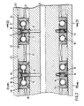
- the support rings have semicircular recesses 15 into which endless tubes 16 surrounding the winding shaft are inserted. With their lateral surface areas facing away from the support rings, these endless hoses in turn engage in semicircular recesses 17 which are provided in pressure plates 18.
- These pressure plates 18 have lugs 19 which, like the parallel keys 12, engage in the continuous axial groove 13, so that the pressure plates are connected in a rotationally fixed manner to the winding shaft 1.
- These support and clamping rings 21 are mounted on the winding shaft 1 in a freely rotatable manner via bearings 22 and, in a known manner, have clamping elements 23 by means of which the individual winding sleeves 24 with the supporting and clamping rings are force or. can be positively connected. If a pressure medium, for example compressed air, is now introduced into the central bore 6 via the connection 7, the individual endless tubes are expanded by this compressed air in such a way that the distance between the pressure plates 18 and the support rings 11 increases, as a result of which a frictional connection to the support - And clamping rings 21 is generated via the friction disks 20.
- a pressure medium for example compressed air
Landscapes
- Winding Of Webs (AREA)
Applications Claiming Priority (4)
| Application Number | Priority Date | Filing Date | Title |
|---|---|---|---|
| DE4000923 | 1990-01-15 | ||
| DE4000923 | 1990-01-15 | ||
| DE4009849 | 1990-03-27 | ||
| DE4009849A DE4009849A1 (de) | 1990-01-15 | 1990-03-27 | Wickelwelle |
Publications (2)
| Publication Number | Publication Date |
|---|---|
| EP0437751A2 true EP0437751A2 (fr) | 1991-07-24 |
| EP0437751A3 EP0437751A3 (en) | 1991-09-25 |
Family
ID=25889054
Family Applications (1)
| Application Number | Title | Priority Date | Filing Date |
|---|---|---|---|
| EP19900124268 Withdrawn EP0437751A3 (en) | 1990-01-15 | 1990-12-14 | Reeling mandrel |
Country Status (4)
| Country | Link |
|---|---|
| US (1) | US5137224A (fr) |
| EP (1) | EP0437751A3 (fr) |
| JP (1) | JPH05319640A (fr) |
| DE (1) | DE4009849A1 (fr) |
Cited By (1)
| Publication number | Priority date | Publication date | Assignee | Title |
|---|---|---|---|---|
| DE102011010378A1 (de) * | 2011-02-04 | 2012-08-09 | Multivac Sepp Haggenmüller Gmbh & Co. Kg | Aufwickler zum Aufwickeln von Folienresten |
Families Citing this family (4)
| Publication number | Priority date | Publication date | Assignee | Title |
|---|---|---|---|---|
| DE4244218C1 (de) * | 1992-12-24 | 1994-04-07 | Hans Heuser | Friktionswickelwelle |
| DE19709078C2 (de) * | 1997-03-06 | 2002-07-18 | Hermann Essert | Friktionswickelwelle |
| US6267318B1 (en) * | 1999-08-30 | 2001-07-31 | Convertech, Inc. | Differential winding rate core winding apparatus |
| JP4386442B2 (ja) * | 2005-03-22 | 2009-12-16 | 富士フイルム株式会社 | ウェブ巻取装置及びスペーサ |
Family Cites Families (6)
| Publication number | Priority date | Publication date | Assignee | Title |
|---|---|---|---|---|
| FR94782E (fr) * | 1966-09-20 | 1969-11-21 | Creil Const Mec | Perfectionnements apportés a l'enroulement sur un meme mandrin d'une pluralité de bandes. |
| DE2220159C3 (de) * | 1972-04-25 | 1981-07-02 | Agfa-Gevaert Ag, 5090 Leverkusen | Wickelwelle zum Aufwickeln von Bändern |
| US3934833A (en) * | 1974-09-27 | 1976-01-27 | General Electric Company | Hysteresis clutch for film winding |
| US4063692A (en) * | 1976-06-11 | 1977-12-20 | Vista Developments, Inc. | Web winding apparatus |
| DE3615479A1 (de) * | 1986-05-07 | 1987-11-12 | Kampf Gmbh & Co Maschf | Wickelwelle mit friktionskoerpern |
| JPH0784280B2 (ja) * | 1987-07-03 | 1995-09-13 | 富士写真フイルム株式会社 | ハブのセット装置 |
-
1990
- 1990-03-27 DE DE4009849A patent/DE4009849A1/de not_active Withdrawn
- 1990-12-14 EP EP19900124268 patent/EP0437751A3/de not_active Withdrawn
- 1990-12-18 JP JP2403240A patent/JPH05319640A/ja active Pending
-
1991
- 1991-01-15 US US07/642,317 patent/US5137224A/en not_active Expired - Fee Related
Cited By (4)
| Publication number | Priority date | Publication date | Assignee | Title |
|---|---|---|---|---|
| DE102011010378A1 (de) * | 2011-02-04 | 2012-08-09 | Multivac Sepp Haggenmüller Gmbh & Co. Kg | Aufwickler zum Aufwickeln von Folienresten |
| EP2484613A3 (fr) * | 2011-02-04 | 2012-12-26 | Multivac Sepp Haggenmüller GmbH & Co. KG | Enrouleur pour l'enroulement de restes de feuilles |
| DE102011010378B4 (de) * | 2011-02-04 | 2014-01-09 | Multivac Sepp Haggenmüller Gmbh & Co. Kg | Aufwickler zum Aufwickeln von Folienresten |
| US8998122B2 (en) | 2011-02-04 | 2015-04-07 | Multivac Sepp Haggenmueller Gmbh & Co. Kg | Winder for film trim winding |
Also Published As
| Publication number | Publication date |
|---|---|
| JPH05319640A (ja) | 1993-12-03 |
| EP0437751A3 (en) | 1991-09-25 |
| US5137224A (en) | 1992-08-11 |
| DE4009849A1 (de) | 1991-07-18 |
Similar Documents
| Publication | Publication Date | Title |
|---|---|---|
| DE2522033C2 (de) | Treibscheibentriebwerk | |
| CH657680A5 (de) | Schleppwalze zur druckbehandlung von warenbahnen. | |
| DE2527690C3 (de) | Bandhaspel zum Auf- und Abwickeln von Metallbändern | |
| DE751212C (de) | Verfahren zum Auswalzen von insbesondere breiten und duennen Metallstreifen oder -baendern | |
| EP0863101B1 (fr) | Arbre d'enroulement avec accouplement à friction | |
| DE2220025A1 (de) | Band-Spreizvorrichtung | |
| DE2357208C3 (de) | Zugwalzenpaar für eine Rotationsmaschine zum Transportieren von Papierbahnen | |
| EP0437751A2 (fr) | Arbre d'enroulement | |
| WO2008145101A1 (fr) | Bobine pour une bande qui peut être enroulée et déroulée en spirale | |
| DD228233A5 (de) | Vorrichtung zum herstellen von gleichmaessig und dicht gewickelten bandrollen | |
| DE2905631C2 (de) | Walzgerüst mit mindestens einer von einer losen drehbaren Hülse umgebenden Stützwalze | |
| DE3718646A1 (de) | Vorrichtung zum axialen verschieben von sich drehenden walzwerkswalzen | |
| DE2220159C3 (de) | Wickelwelle zum Aufwickeln von Bändern | |
| DE4026238C1 (fr) | ||
| DE1944099C3 (de) | Registrierpapierantrieb | |
| DE8903793U1 (de) | Vorrichtung zum Zusammensetzen von Furnieren | |
| AT262739B (de) | Antriebsspindel zum Wickeln von Streifen aus Folienmaterial | |
| DE3109863A1 (de) | Haspeldorn zum aufwickeln von gespaltenen schmalbaendern | |
| DE8004622U1 (de) | Spannvorrichtung | |
| DE1802544A1 (de) | Treibrolle,insbesondere fuer Blech- und Bandwalzenstrassen | |
| DE3615479C2 (fr) | ||
| EP0574682A2 (fr) | Accouplement à friction d'un arbre avec un élément de machine | |
| DE1502047C (de) | Spanndorn fur Werkstucke | |
| DE29500338U1 (de) | Preßgerät | |
| AT137760B (de) | Maschine zum Aufbringen von Zementmasse auf metallische zylindrische Tragkörper. |
Legal Events
| Date | Code | Title | Description |
|---|---|---|---|
| PUAI | Public reference made under article 153(3) epc to a published international application that has entered the european phase |
Free format text: ORIGINAL CODE: 0009012 |
|
| AK | Designated contracting states |
Kind code of ref document: A2 Designated state(s): CH DE DK FR GB IT LI |
|
| PUAL | Search report despatched |
Free format text: ORIGINAL CODE: 0009013 |
|
| AK | Designated contracting states |
Kind code of ref document: A3 Designated state(s): CH DE DK FR GB IT LI |
|
| 17P | Request for examination filed |
Effective date: 19920226 |
|
| 17Q | First examination report despatched |
Effective date: 19930716 |
|
| STAA | Information on the status of an ep patent application or granted ep patent |
Free format text: STATUS: THE APPLICATION IS DEEMED TO BE WITHDRAWN |
|
| 18D | Application deemed to be withdrawn |
Effective date: 19931127 |