EP0437868B2 - Appareil et procédé pour réduire le flottement d'une surface portante d'avion - Google Patents
Appareil et procédé pour réduire le flottement d'une surface portante d'avion Download PDFInfo
- Publication number
- EP0437868B2 EP0437868B2 EP90200161A EP90200161A EP0437868B2 EP 0437868 B2 EP0437868 B2 EP 0437868B2 EP 90200161 A EP90200161 A EP 90200161A EP 90200161 A EP90200161 A EP 90200161A EP 0437868 B2 EP0437868 B2 EP 0437868B2
- Authority
- EP
- European Patent Office
- Prior art keywords
- wing
- aircraft
- strut
- flutter
- wing element
- Prior art date
- Legal status (The legal status is an assumption and is not a legal conclusion. Google has not performed a legal analysis and makes no representation as to the accuracy of the status listed.)
- Expired - Lifetime
Links
- 238000000034 method Methods 0.000 title description 6
- 238000005452 bending Methods 0.000 claims description 20
- 230000010355 oscillation Effects 0.000 claims description 10
- 230000033001 locomotion Effects 0.000 description 5
- 239000000463 material Substances 0.000 description 5
- 238000013016 damping Methods 0.000 description 3
- 230000033228 biological regulation Effects 0.000 description 2
- 230000003247 decreasing effect Effects 0.000 description 2
- 238000010586 diagram Methods 0.000 description 2
- 230000003534 oscillatory effect Effects 0.000 description 2
- 241000256259 Noctuidae Species 0.000 description 1
- 230000003416 augmentation Effects 0.000 description 1
- 238000007796 conventional method Methods 0.000 description 1
- 230000001419 dependent effect Effects 0.000 description 1
- 239000000284 extract Substances 0.000 description 1
- 238000009434 installation Methods 0.000 description 1
- 239000000203 mixture Substances 0.000 description 1
- 230000002265 prevention Effects 0.000 description 1
- 230000001629 suppression Effects 0.000 description 1
Images


Classifications
-
- B—PERFORMING OPERATIONS; TRANSPORTING
- B64—AIRCRAFT; AVIATION; COSMONAUTICS
- B64D—EQUIPMENT FOR FITTING IN OR TO AIRCRAFT; FLIGHT SUITS; PARACHUTES; ARRANGEMENT OR MOUNTING OF POWER PLANTS OR PROPULSION TRANSMISSIONS IN AIRCRAFT
- B64D27/00—Arrangement or mounting of power plants in aircraft; Aircraft characterised by the type or position of power plants
- B64D27/02—Aircraft characterised by the type or position of power plants
- B64D27/16—Aircraft characterised by the type or position of power plants of jet type
- B64D27/18—Aircraft characterised by the type or position of power plants of jet type within, or attached to, wings
-
- B—PERFORMING OPERATIONS; TRANSPORTING
- B64—AIRCRAFT; AVIATION; COSMONAUTICS
- B64D—EQUIPMENT FOR FITTING IN OR TO AIRCRAFT; FLIGHT SUITS; PARACHUTES; ARRANGEMENT OR MOUNTING OF POWER PLANTS OR PROPULSION TRANSMISSIONS IN AIRCRAFT
- B64D27/00—Arrangement or mounting of power plants in aircraft; Aircraft characterised by the type or position of power plants
- B64D27/40—Arrangements for mounting power plants in aircraft
- B64D27/402—Arrangements for mounting power plants in aircraft comprising box like supporting frames, e.g. pylons or arrangements for embracing the power plant
-
- Y—GENERAL TAGGING OF NEW TECHNOLOGICAL DEVELOPMENTS; GENERAL TAGGING OF CROSS-SECTIONAL TECHNOLOGIES SPANNING OVER SEVERAL SECTIONS OF THE IPC; TECHNICAL SUBJECTS COVERED BY FORMER USPC CROSS-REFERENCE ART COLLECTIONS [XRACs] AND DIGESTS
- Y02—TECHNOLOGIES OR APPLICATIONS FOR MITIGATION OR ADAPTATION AGAINST CLIMATE CHANGE
- Y02T—CLIMATE CHANGE MITIGATION TECHNOLOGIES RELATED TO TRANSPORTATION
- Y02T50/00—Aeronautics or air transport
- Y02T50/40—Weight reduction
Definitions
- the present invention pertains to an aircraft configured for preventing wing flutter as described in the preamble of claim 1.
- Such an aircraft is known from H. Katz, 'Flutter of Aircraft with External Stores'. McDonnell Aircraft Company, St Louis, Missouri 63166, presented at the Aircraft/Stores Compatibility Symposium, November 1969.
- wing flutter refers to a phenomenon in which the wing oscillations between the bended state and the unbended state do not damp out. Rather, the amplitude of these oscillations either remains constant or increases over time.
- Wing flutter is an aeroelastic instability produced by the coalescing and proper phasing of two or more structural vibration modes of an aircraft in flight.
- a flutter mode usually involves both bending and torsion types of motion in which the torsional motion extracts energy from the airstream and drives the bending mode to increasingly higher amplitudes. In other cases these oscillations are lightly damped, but stable, within the operating speed envelope of the aircraft and can cause a reduction in the riding comfort of the aircraft.
- the location of the engine nacelle relative to the wing, the mass properties of the engine, and the stiffness of the strut which attaches the nacelle to the wing are factors which influence the flutter characteristics of the wing. More specifically, the natural frequency of the nacelle and the manner of strut installation can influence the mode and airspeed at which the wing oscillations become unstable (flutter).
- the natural frequency of the nacelles and nacelle struts are restricted within a narrow range.
- the outboard engine nacelles are permitted to oscillate at a natural frequency of about two cycles per second in a lateral direction. If the outboard engine nacelle lateral frequencies are significantly above or below two cycles per second then wing flutter can result at an unacceptably low airspeed.
- US-A-2 124 098 by Younger pertains to an airfoil flutter damping device which includes an auxiliary airfoil device which attaches to a main airfoil to counteract flutter forces in the main airfoil.
- US-A-3 327 965 by Bockrath discusses a damping device which dissipates the oscillatory energy transmitted from an aircraft wing to an attached engine nacelle in order to prevent undesirable motion of the engine nacelle.
- a pneumatic spring system for suspending a store from wing in order to reduce wing flutter is disclosed in US-A-4 343 447 by Reed III.
- US-A-4 502 652 by Breitbach pertains to a spring device for suppressing wing flutter when carrying external loads.
- the present invention seeks to provide an aircraft having improved flutter characteristics in its normal clean 'fly-away condition. According to the invention, this is accomplished in an aircraft as described in the preamble of claim 1, in that the first and second wing elements are engine nacelles which are suspended from the first and second wings, and the attaching means of which have different side bending frequencies.
- the present invention pertains to an aircraft configured to prevent wing flutter by causing the port and starboard wings of an aircraft to oscillate at different frequencies.
- the wing has one or more engine nacelles attached to both the port and starboard wings of an aircraft in a manner to reduce wing flutter.
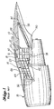
- FIG. 1 there is shown a conventional method of attaching an engine nacelle indicated at 10 to a wing 12 by means of a conventional strut assembly indicated at 14.
- the strut assembly 14 has a somewhat trapezoidal cross-sectional configuration.
- the strut 14 (FIG. 1 ) is connected to the wing 12 by a rearward extending upper linking rod 16 which has a forward end connected by a connector 18 to an upper portion 20 of the strut, and a rear end connected by a connector 22 to a spar 21 of the wing.
- the engine nacelle 10 is connected to the strut 14 in a conventional manner by means of a forward mount 36 and an aft mount 38.
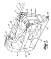
- the strut 14 (FIG. 1) is formed by a number of vertical, spanwise bulkheads 40 which are joined at their lower ends by a fore and aft extending lower spar 42, at their midsections by a midspar 44, and at their upper ends by an upper spar 46.
- a number of the rear bulkheads 40 are shorter in height than the forward bulkheads. These shorter bulkheads include a rearmost bulkhead 40a, while the taller forward bulkheads include a rearmost bulkheac 40b.
- a portion of the conventional strut 14 is shown extending from just forward of the bulkhead 40b in a rearward directior and terminating at the bulkhead 40a.
- the midspar 44 is formed by a pair of fore and aft extending beams 48 which are joined together at the bulkhead 40a by a crossbeam 50. Attached to the aft end of each beam 48 at the crossbeam 50 is a female portion 51 of the connector 26 which is attached to a male portion (not shown) of the connector which in turn is mounted to the wing.
- the male and female connector portions are held together by a lateral pin (not shown) which extends through openings in the male and female portions.
- a male portion 53 of the connector 30 is mounted to the aft end of the lower spar 42.
- a male portion 55 of the upper fitting 22 is attached to the aft end of the upper spar 46 to further secure the strut to the wing.
- the strut is further formed by a closure spar which includes a pair of beams 59 which extend downward and rearward from the bulkhead 40b and which are connected to the aft end of the midspar 44.
- a fairing skin 60 encloses the strut to reduce aerodynamic drag.
- FIG. 3 there is shown a simplified diagram of the wing 12 which supports the engine nacelle 10 by means of the conventional strut 14 at the connectors 26.
- a lateral force F L is applied to the nacelle 10
- vertical forces F v and -F v are generated through the connectors 26 and the strut 14 to form a couple.
- a lateral force -F L acts on the nacelle in the opposite direction
- vertical forces -F v and F v react through the connectors 26 to the wing. In this manner an oscillatory force on the nacelle is transmitted into the wing.
- the lateral natural frequency of oscillation of the nacelle is, in part, determined by the stiffness of the strut, which in turn is controlled by careful design of the strut structural components such as spars and bulkheads.
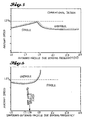
- the importance of the nacelle lateral frequency becomes apparent by reference to FIG. 4 which is a graph of flutter speed as function of nacelle lateral frequency for an aircraft in which all of the struts have the previously described conventional configuration.
- the lateral frequency of a nacelle and strut on the port wing is configured to be identical to a similarly positioned nacelle and strut on the starboard wing (referred to as a "symmetrical design").
- a wing In accordance with federal regulations, a wing must have a flutter speed of at least 1.2 times the aircraft certified dive speed. As shown in the exemplary graph in FIG. 4, there is a window between about 1.8 and 2.0 cycles per second (Hz) of nacelle side bending frequency where the airspeed of the aircraft can reach 1.2 V d and still avoid wing flutter. In this case, the conventional strut described previously can be "tuned" so that the nacelle side bending frequency is located inside the window.
- this flutter window is essentially closed.
- the onset of wing flutter occurs at airspeeds below 1.2V d , with the highest airspeed obtainable being at a side bending frequency of slightly below 1.9 Hz.
- This conventional configuration would require that the maximum operating speed of the aircraft be reduced to avoid flutter.
- the wing could be stiffened to raise the flutter speed above 1.2V d .
- the additional stiffness material would add a weight penalty to the aircraft.
- the strut design of the present invention overcomes this problem without a speed reduction or the weight penalty of additional wing stiffening. It has been found that when the nacelle attachment struts are configured so that a nacelle on the port wing has a side bending frequency that is different from the side bending frequency of a nacelle on the starboard wing (the nacelles being located in the same relative positions on opposite wings, e.g. starboard outboard position and port outboard position), that flutter is eliminated or at least postponed until significantly higher airspeeds.
- This concept of providing port and starboard struts which allow the nacelles at opposite sides of the fuselage to have different side bending frequencies is quite different from the conventional manner of attaching the nacelles so that the left and right struts are tuned to a common side bending frequency. More broadly, the present invention operates to eliminate wing flutter by configuring the aircraft so that the port and starboard wings oscillate at different natural frequencies.
- FIG. 7 an attachment strut shown in FIG. 7, in which elements common to the conventional strut described with reference to FIGS. 1 and 2, will be identified by common numerals with a prime (') suffix attached.
- FIG. 7 a portion of a strut indicated at 70 for attaching an engine nacelle to a wing. This portion of the strut extends rearward from bulkhead 40b' and terminates at a rear bulkhead 40c.
- This design provides a pair of parallel spring beams 72 in place of the connectors 26 in FIG. 1 to connect the strut to the wing.
- each spring beam 72 extends in a fore and aft direction so that a forward end 74 of each spring beam is fastened to the bulkhead 40b'.
- the midspar of FIG. 1 is formed by left, right parallel beams 75 which extend rearward from the bulkhead 40b'. Located outboard of each beam 75 is one of the spring beams 72.
- a female portion of a connector 78 which is attached to the wing in a conventional manner.
- the natural side bending frequencies of the nacelles on the left and right wings are different.
- the different side bending frequencies are achieved by spring beams 72 of different stiffnesses in the left and right nacelle struts.
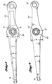
- the spring beam 72 (FIG. 8) in the right outboard nacelle strut of a Boeing 747 aircraft has a larger cross sectional height dimension h than the cross sectional height dimension h' of the spring beam 72' (FIG. 9) in the port outboard nacelle strut.
- the primed numbers refer to starboard spring beam components and the unprimed numbers refer to port components.
- the starboard outboard nacelle strut is stiffer than the port outboard nacelle strut. It is this difference in vertical flexibility along the respective lengthwise axes of the spring beams of the port and starboard nacelle struts which is a unique feature of the present invention.
- each spring beam 72 there is located between the forward and aft ends of each spring beam 72 a rotary bearing 79.
- the rotary bearing 79 is supported in a trunnion 80 by a pin (not shown) which extends through sideholes in the trunnion and through a central opening 81 in the bearing 79.
- Left, right trunnions 80 are attached to the aft ends of the beams 75 which form the midspar.
- Support for each trunnion 80 is provided by a bulkhead 40d.
- the bulkhead 40d is attached to the lower spar 42' at its lower end, and to the bottom of each trunnion 80 at its upper end.
- the upper end of the bulkhead 40d is also attached to the rear ends of the midspar beams 75.
- a lateral force F L (FIG. 7) exerted against the engine nacelle generates similar force components F v , -F v described with reference to FIGS. 3A and 3B.
- These forces act in opposite vertical directions to cause up and down movement of the cantilevered portions of the spring beams.
- the flexibility of the spring beams it is possible to control the natural frequency of oscillation of the engine nacelle. More specifically, by controlling the vertical and/or thickness dimensions of the spring beam as well its material composition, the precise stiffness of the beam is controlled in a known manner.
- the side bending frequency of the engine nacelle is a function of the stiffness of the spring beam.
- the conventional struts 14 shown in FIGS. 1 and 2 are used to attach the inboard engine nacelles to the port and starboard wings of a Boeing 747 aircraft, while the struts 70 of the present invention are used to attach the outboard engine nacelles to the port and starboard wings.
- the inboard struts are tuned so that the nacelle side bending frequency of each is the same
- the port outboard strut is adjusted so that the nacelle has a side bending frequency of 1.76Hz
- the opposite outboard strut is adjusted so that the nacelle side bending frequency is 2.11 Hz.
- wing flutter was avoided to speeds above 1.2 V d .
Landscapes
- Engineering & Computer Science (AREA)
- Aviation & Aerospace Engineering (AREA)
- Wind Motors (AREA)
- Tires In General (AREA)
- Structures Of Non-Positive Displacement Pumps (AREA)
Claims (6)
- Aéronef ayant une configuration destinée à empêcher le flottement des ailes, l'aéronef comprenant :a) une première aile (12) et une seconde aile (12) placées sur des côtés opposés de l'aéronef,b) un premier élément (10) d'aile et un second élément (10) d'aile,c) un premier dispositif (70) de fixation du premier élément (10) d'aile à la première aile (12) et un second dispositif (70) de fixation du second élément (10) d'aile à la seconde aile (12),le premier et le second élément (10) d'aile étant fixé à l'aile associée (12) de manière que, lorsque le premier élément (10) d'aile et le second élément (10) d'aile sont soumis à une force, le premier élément (10) d'aile soit mis en oscillation à une fréquence différente de celle du second élément (10) d'aile, etle premier dispositif (70) de fixation comporte un dispositif de transmission d'oscillations du premier élément (10) d'aile à la première aile (12), et le second dispositif (70) de fixation comporte un dispositif de transmission d'oscillations du second élément (10) d'aile à la seconde aile (12), d'une manière telle que la première aile (12) oscille à une fréquence différente de celle de la seconde aile (12), caractérisé en ce que le premier et le second élément (10) d'aile sont des nacelles de réacteurs qui sont suspendues à la première et à la seconde aile (12), et dont les dispositifs de fixation (70) ont des fréquences différentes de flexion latérale.
- Aéronef selon la revendication 1, caractérisé en ce quea) le premier dispositif de fixation (70) comporte un premier organe (72) et le second dispositif de fixation (70) comporte un second organe (72'), etb) le premier organe (72) a une rigidité différente de celle du second organe (72') afin que, lorsque le premier et le second élément d'aile (12) sont soumis à la force, le premier élément d'aile (12) oscille à une fréquence différente de celle du second élément d'aile (12).
- Aéronef selon la revendication 2, caractérisé en ce quea) le premier organe (72) a une première dimension en coupe (h),b) le second organe (72') a une seconde dimension en coupe (h') qui est différente de la première dimension en coupe (h), si bien que le premier organe (72) a une rigidité différente de celle du second organe (72').
- Aéronef selon l'une quelconque des revendications 1 à 3, caractérisé en ce quea) le premier dispositif de fixation (70) comporte un premier mât destiné à suspendre le premier élément d'aile (10) au premier dispositif à aile (12),b) le second dispositif de fixation (70) comporte un second mât destiné à suspendre le second élément d'aile (10) au second dispositif à aile (12).
- Aéronef selon la revendication 4, caractérisé en ce que chaque mât (70) comportelorsque l'élément associé d'aile (10) est soumis à une force latérale (F1), la seconde extrémité (78) en porte-à-faux du premier dispositif allongé (72) et la seconde extrémité en porte-à-faux (78) du second dispositif allongé (72) se déplacent en sens opposés en direction verticale.1) un dispositif à châssis (40-46),2) un premier dispositif allongé (72) ayant une première extrémité (74) qui est fixée au dispositif à châssis (40-46), et une seconde extrémité (78) qui est fixée au dispositif associé à aile (12),3) un dispositif (79, 80) de raccordement du premier dispositif allongé (72) au dispositif à châssis (40-46) entre la première extrémité (74) et la seconde extrémité (78) afin que la seconde extrémité (78) soit suspendue en porte-à-faux,4) un second dispositif allongé (72) ayant une première extrémité (74) qui est fixée au dispositif à châssis (40-46) et une seconde extrémité (78) qui est fixée au dispositif associé à aile (12),5) un dispositif (29, 30) de raccordement du second dispositif allongé (72) au dispositif à châssis (40-46) entre la première extrémité (74) et la seconde extrémité (78) du second dispositif allongé (72) afin que la seconde extrémité (78) soit suspendue en porte-à-faux, et
- Aéronef selon la revendication 5, caractérisé en ce que le mât comprend un tourillon (80) raccordé au dispositif à châssis (40-46) et supportant le premier organe (72) afin qu'il permette la rotation de la seconde extrémité (78) du premier organe (72) par rapport au dispositif à châssis (40-46).
Priority Applications (1)
| Application Number | Priority Date | Filing Date | Title |
|---|---|---|---|
| DE1990611308 DE69011308T3 (de) | 1990-01-19 | 1990-01-19 | Gerät und Verfahren zur Reduzierung des Flatterns einer tragenden Fläche eines Flugzeuges. |
Applications Claiming Priority (1)
| Application Number | Priority Date | Filing Date | Title |
|---|---|---|---|
| US07/269,839 US4917331A (en) | 1988-11-10 | 1988-11-10 | Apparatus and methods for reducing aircraft lifting surface flutter |
Publications (3)
| Publication Number | Publication Date |
|---|---|
| EP0437868A1 EP0437868A1 (fr) | 1991-07-24 |
| EP0437868B1 EP0437868B1 (fr) | 1994-08-03 |
| EP0437868B2 true EP0437868B2 (fr) | 2001-05-02 |
Family
ID=23028866
Family Applications (1)
| Application Number | Title | Priority Date | Filing Date |
|---|---|---|---|
| EP90200161A Expired - Lifetime EP0437868B2 (fr) | 1988-11-10 | 1990-01-19 | Appareil et procédé pour réduire le flottement d'une surface portante d'avion |
Country Status (2)
| Country | Link |
|---|---|
| US (1) | US4917331A (fr) |
| EP (1) | EP0437868B2 (fr) |
Families Citing this family (16)
| Publication number | Priority date | Publication date | Assignee | Title |
|---|---|---|---|---|
| US5065959A (en) * | 1989-11-21 | 1991-11-19 | The Boeing Company | Vibration damping aircraft engine attachment |
| JP2788914B2 (ja) | 1990-02-09 | 1998-08-20 | ザ・ボーイング・カンパニー | 翼フラッタを防ぐように構成された航空機および航空機においてフラッタを減少させる方法 |
| FR2676707B1 (fr) * | 1991-05-23 | 1993-08-13 | Snecma | Nacelle pour suspendre sous l'aile d'un avion un groupe turboreacteur du type a double flux. |
| US5176339A (en) * | 1991-09-30 | 1993-01-05 | Lord Corporation | Resilient pivot type aircraft mounting |
| FR2747364B1 (fr) * | 1996-04-15 | 1998-07-03 | Aerospatiale | Procede et dispositif pour amortir les vibrations ou empecher leur apparition sur des cellules d'aeronef en vol transsonique |
| US6095456A (en) * | 1996-12-23 | 2000-08-01 | The Boeing Company | Strut-wing interface having dual upper links |
| US6189830B1 (en) | 1999-02-26 | 2001-02-20 | The Boeing Company | Tuned engine mounting system for jet aircraft |
| GB2360749A (en) * | 2000-03-28 | 2001-10-03 | Rolls Royce Plc | Aircraft turbofan gas turbine engine upstream core mounting which does not transmit vertical loads |
| FR2836672B1 (fr) * | 2002-03-04 | 2004-06-04 | Airbus France | Mat d'accrochage d'un moteur sous une voilure d'aeronef |
| FR2862944B1 (fr) * | 2003-12-01 | 2006-02-24 | Airbus France | Dispositif d'accrochage d'un turbopropulseur sous une voilure d'aeronef |
| FR2891803B1 (fr) * | 2005-10-07 | 2007-11-30 | Airbus France Sas | Structure rigide pour mat d'accrochage de moteur d'aeronef, et mat comportant une telle structure |
| FR2903665B1 (fr) * | 2006-07-11 | 2008-10-10 | Airbus France Sas | Ensemble moteur pour aeronef comprenant un berceau de support de capot de soufflante monte sur deux elements distincts |
| FR2934845A1 (fr) * | 2008-08-11 | 2010-02-12 | Airbus France | Mat de moteur pour aeronef |
| US9388875B2 (en) | 2011-10-18 | 2016-07-12 | The Boeing Company | Aeroelastic tuned mass damper |
| US10604265B2 (en) * | 2016-11-15 | 2020-03-31 | The Boeing Company | Integrated strut support fittings with underwing longerons |
| FR3102151B1 (fr) * | 2019-10-21 | 2021-10-29 | Airbus Operations Sas | Aéronef comprenant une attache voilure arrière présentant au moins deux bielles latérales et un pion de cisaillement |
Family Cites Families (20)
| Publication number | Priority date | Publication date | Assignee | Title |
|---|---|---|---|---|
| US1896270A (en) * | 1929-09-06 | 1933-02-07 | Curtiss Aeroplane & Motor Co | Airplane |
| US1867708A (en) * | 1931-05-25 | 1932-07-19 | Packard Motor Car Co | Automobile construction |
| US1990978A (en) * | 1933-08-02 | 1935-02-12 | Curtiss Aeroplane & Motor Co | Irreversible control |
| US2061242A (en) * | 1933-08-11 | 1936-11-17 | Grover Loening Aircraft Compan | Airplane bracing |
| US2081957A (en) * | 1933-09-01 | 1937-06-01 | Roche Jean Alfred | Dynamic balance of control surfaces |
| US2124098A (en) * | 1933-09-16 | 1938-07-19 | Younger John Elliott | Dampening device |
| US2090775A (en) * | 1934-03-30 | 1937-08-24 | Curtiss Wright Corp | Twisted fairing |
| GB521708A (en) * | 1937-11-23 | 1940-05-29 | Maurice Francois Alexandre Jul | Improvement in suspension devices |
| CH217119A (fr) * | 1937-11-23 | 1941-09-30 | Julien Maurice Francois Alexan | Dispositif de suspension pour des organes placés sur des supports et soumis à des mouvements alternatifs. |
| US2332516A (en) * | 1940-08-12 | 1943-10-26 | Paul H Kemmer | Flutter and vibration prevention device for control surfaces |
| US2398704A (en) * | 1943-05-03 | 1946-04-16 | Ridgefield Mfg Corp | Engine nacelle installation for aircraft |
| US3327965A (en) * | 1965-09-27 | 1967-06-27 | Douglas Aircraft Inc | Flexible engine pylon |
| GB1328410A (en) * | 1969-11-29 | 1973-08-30 | Ver Flugtechnische Werke | Aircraft engine mounting means |
| US3734432A (en) * | 1971-03-25 | 1973-05-22 | G Low | Suppression of flutter |
| US4233883A (en) * | 1979-01-11 | 1980-11-18 | Edo Corporation | Automatically self-adjusting and load-limiting swaybrace system |
| US4343447A (en) * | 1980-03-28 | 1982-08-10 | The United States Of America As Represented By The Administrator Of The National Aeronautics And Space Administration | Decoupler pylon: wing/store flutter suppressor |
| DE3136320C2 (de) * | 1981-09-12 | 1983-10-20 | Deutsche Forschungs- und Versuchsanstalt für Luft- und Raumfahrt e.V., 5000 Köln | Verfahren und Vorrichtung zur Unterdrückung des Außenlast-Tragflügel-Flatterns von Flugzeugen |
| GB8300748D0 (en) * | 1983-01-12 | 1983-02-16 | British Aerospace | Power plant attachment for aircraft wings |
| US4562546A (en) * | 1983-01-13 | 1985-12-31 | Rockwell International Corporation | Stability augmentation system for a forward swept wing aircraft |
| US4616793A (en) * | 1985-01-10 | 1986-10-14 | The United States Of America As Represented By The Administrator Of The National Aeronautics And Space Administration | Remote pivot decoupler pylon: wing/store flutter suppressor |
-
1988
- 1988-11-10 US US07/269,839 patent/US4917331A/en not_active Expired - Lifetime
-
1990
- 1990-01-19 EP EP90200161A patent/EP0437868B2/fr not_active Expired - Lifetime
Also Published As
| Publication number | Publication date |
|---|---|
| EP0437868B1 (fr) | 1994-08-03 |
| US4917331A (en) | 1990-04-17 |
| EP0437868A1 (fr) | 1991-07-24 |
Similar Documents
| Publication | Publication Date | Title |
|---|---|---|
| US5054715A (en) | Apparatus and methods for reducing aircraft lifting surface flutter | |
| EP0437868B2 (fr) | Appareil et procédé pour réduire le flottement d'une surface portante d'avion | |
| EP1031507B1 (fr) | Dispositif de fixation pour moteur d'aéronef à réaction accordé | |
| US5065959A (en) | Vibration damping aircraft engine attachment | |
| US6607161B1 (en) | Convertible aircraft with tilting rotors | |
| US5909858A (en) | Spanwise transition section for blended wing-body aircraft | |
| EP0899190A2 (fr) | Système de reconfiguration pour aile d'avion | |
| US5046684A (en) | Airplane with braced wings and pivoting propulsion devices | |
| US20140061367A1 (en) | Compound helicopter | |
| CA3050051C (fr) | Un helicoptere compose equipe d'un arrangement de voilure fixe | |
| US4643376A (en) | Shock inducing pod for causing flow separation | |
| US3902688A (en) | I-tail empennage | |
| US10752333B2 (en) | Wing-fuselage integrated airframe beams for tiltrotor aircraft | |
| RU2082651C1 (ru) | Легкий летательный аппарат | |
| WO2006022813A2 (fr) | Avion a fuselage duel haute portance, faible trainee | |
| US2793826A (en) | Split aircraft wing | |
| US5890675A (en) | Process and device for damping vibrations or preventing their appearance in aircraft airframes in transonic flight | |
| JP2788914B2 (ja) | 翼フラッタを防ぐように構成された航空機および航空機においてフラッタを減少させる方法 | |
| RU2152892C1 (ru) | Летательный аппарат вертикального взлета и мягкой вертикальной посадки с тягой, меньшей веса | |
| RU2023628C1 (ru) | Летательный аппарат | |
| CA1333901C (fr) | Aeronef a ailerons cylindriques detachables | |
| Pratt | A survey of active controls benefits to supersonic transports | |
| DE69011308T3 (de) | Gerät und Verfahren zur Reduzierung des Flatterns einer tragenden Fläche eines Flugzeuges. | |
| RU2112705C1 (ru) | Петраплан | |
| EP3919377B1 (fr) | Hélicoptère combiné |
Legal Events
| Date | Code | Title | Description |
|---|---|---|---|
| PUAI | Public reference made under article 153(3) epc to a published international application that has entered the european phase |
Free format text: ORIGINAL CODE: 0009012 |
|
| AK | Designated contracting states |
Kind code of ref document: A1 Designated state(s): DE FR GB IT NL |
|
| 17P | Request for examination filed |
Effective date: 19911202 |
|
| 17Q | First examination report despatched |
Effective date: 19930503 |
|
| GRAA | (expected) grant |
Free format text: ORIGINAL CODE: 0009210 |
|
| AK | Designated contracting states |
Kind code of ref document: B1 Designated state(s): DE FR GB IT NL |
|
| PG25 | Lapsed in a contracting state [announced via postgrant information from national office to epo] |
Ref country code: IT Free format text: LAPSE BECAUSE OF FAILURE TO SUBMIT A TRANSLATION OF THE DESCRIPTION OR TO PAY THE FEE WITHIN THE PRE;WARNING: LAPSES OF ITALIAN PATENTS WITH EFFECTIVE DATE BEFORE 2007 MAY HAVE OCCURRED AT ANY TIME BEFORE 2007. THE CORRECT EFFECTIVE DATE MAY BE DIFFERENT FROM THE ONE RECORDED.SCRIBED TIME-LIMIT Effective date: 19940803 |
|
| REF | Corresponds to: |
Ref document number: 69011308 Country of ref document: DE Date of ref document: 19940908 |
|
| ET | Fr: translation filed | ||
| PLBI | Opposition filed |
Free format text: ORIGINAL CODE: 0009260 |
|
| 26 | Opposition filed |
Opponent name: DAIMLER-BENZ AEROSPACE AIRBUS GMBH PJ3 - PATENTABT Effective date: 19950430 |
|
| NLR1 | Nl: opposition has been filed with the epo |
Opponent name: DAIMLER-BENZ AEROSPACE AIRBUS GMBH PJ3 - PATENTABT |
|
| PLBF | Reply of patent proprietor to notice(s) of opposition |
Free format text: ORIGINAL CODE: EPIDOS OBSO |
|
| PLAW | Interlocutory decision in opposition |
Free format text: ORIGINAL CODE: EPIDOS IDOP |
|
| APAC | Appeal dossier modified |
Free format text: ORIGINAL CODE: EPIDOS NOAPO |
|
| APAE | Appeal reference modified |
Free format text: ORIGINAL CODE: EPIDOS REFNO |
|
| APAC | Appeal dossier modified |
Free format text: ORIGINAL CODE: EPIDOS NOAPO |
|
| PLAB | Opposition data, opponent's data or that of the opponent's representative modified |
Free format text: ORIGINAL CODE: 0009299OPPO |
|
| R26 | Opposition filed (corrected) |
Opponent name: DAIMLERCHRYSLER AEROSPACE AIRBUS GMBH PJ3 - PATENT Effective date: 19950430 |
|
| NLR1 | Nl: opposition has been filed with the epo |
Opponent name: DAIMLERCHRYSLER AEROSPACE AIRBUS GMBH PJ3 - PATENT |
|
| APAC | Appeal dossier modified |
Free format text: ORIGINAL CODE: EPIDOS NOAPO |
|
| PLAW | Interlocutory decision in opposition |
Free format text: ORIGINAL CODE: EPIDOS IDOP |
|
| PUAH | Patent maintained in amended form |
Free format text: ORIGINAL CODE: 0009272 |
|
| STAA | Information on the status of an ep patent application or granted ep patent |
Free format text: STATUS: PATENT MAINTAINED AS AMENDED |
|
| 27A | Patent maintained in amended form |
Effective date: 20010502 |
|
| AK | Designated contracting states |
Kind code of ref document: B2 Designated state(s): DE FR GB IT NL |
|
| NLR2 | Nl: decision of opposition | ||
| NLR3 | Nl: receipt of modified translations in the netherlands language after an opposition procedure | ||
| ET3 | Fr: translation filed ** decision concerning opposition | ||
| REG | Reference to a national code |
Ref country code: GB Ref legal event code: IF02 |
|
| REG | Reference to a national code |
Ref country code: DE Ref legal event code: 8570 |
|
| APAH | Appeal reference modified |
Free format text: ORIGINAL CODE: EPIDOSCREFNO |
|
| PGFP | Annual fee paid to national office [announced via postgrant information from national office to epo] |
Ref country code: DE Payment date: 20090302 Year of fee payment: 20 Ref country code: NL Payment date: 20090124 Year of fee payment: 20 |
|
| PGFP | Annual fee paid to national office [announced via postgrant information from national office to epo] |
Ref country code: GB Payment date: 20090129 Year of fee payment: 20 |
|
| PGFP | Annual fee paid to national office [announced via postgrant information from national office to epo] |
Ref country code: FR Payment date: 20090119 Year of fee payment: 20 |
|
| REG | Reference to a national code |
Ref country code: GB Ref legal event code: PE20 Expiry date: 20100118 |
|
| NLV7 | Nl: ceased due to reaching the maximum lifetime of a patent |
Effective date: 20100119 |
|
| PG25 | Lapsed in a contracting state [announced via postgrant information from national office to epo] |
Ref country code: GB Free format text: LAPSE BECAUSE OF EXPIRATION OF PROTECTION Effective date: 20100118 |
|
| PG25 | Lapsed in a contracting state [announced via postgrant information from national office to epo] |
Ref country code: NL Free format text: LAPSE BECAUSE OF EXPIRATION OF PROTECTION Effective date: 20100119 |
|
| PG25 | Lapsed in a contracting state [announced via postgrant information from national office to epo] |
Ref country code: DE Free format text: LAPSE BECAUSE OF EXPIRATION OF PROTECTION Effective date: 20100119 |