EP0437919B1 - Pompe à déplacement positif à palettes - Google Patents
Pompe à déplacement positif à palettes Download PDFInfo
- Publication number
- EP0437919B1 EP0437919B1 EP90311094A EP90311094A EP0437919B1 EP 0437919 B1 EP0437919 B1 EP 0437919B1 EP 90311094 A EP90311094 A EP 90311094A EP 90311094 A EP90311094 A EP 90311094A EP 0437919 B1 EP0437919 B1 EP 0437919B1
- Authority
- EP
- European Patent Office
- Prior art keywords
- pump
- pump units
- vanes
- shaft
- units
- Prior art date
- Legal status (The legal status is an assumption and is not a legal conclusion. Google has not performed a legal analysis and makes no representation as to the accuracy of the status listed.)
- Expired - Lifetime
Links
- 238000006073 displacement reaction Methods 0.000 title claims description 9
- 125000006850 spacer group Chemical group 0.000 claims description 34
- 239000012530 fluid Substances 0.000 description 9
- 238000010420 art technique Methods 0.000 description 4
- 238000010276 construction Methods 0.000 description 2
- 238000000034 method Methods 0.000 description 2
- 230000008878 coupling Effects 0.000 description 1
- 238000010168 coupling process Methods 0.000 description 1
- 238000005859 coupling reaction Methods 0.000 description 1
- 230000000694 effects Effects 0.000 description 1
- 238000003754 machining Methods 0.000 description 1
- 230000036316 preload Effects 0.000 description 1
- 230000000717 retained effect Effects 0.000 description 1
- 238000007789 sealing Methods 0.000 description 1
Images
Classifications
-
- F—MECHANICAL ENGINEERING; LIGHTING; HEATING; WEAPONS; BLASTING
- F04—POSITIVE - DISPLACEMENT MACHINES FOR LIQUIDS; PUMPS FOR LIQUIDS OR ELASTIC FLUIDS
- F04C—ROTARY-PISTON, OR OSCILLATING-PISTON, POSITIVE-DISPLACEMENT MACHINES FOR LIQUIDS; ROTARY-PISTON, OR OSCILLATING-PISTON, POSITIVE-DISPLACEMENT PUMPS
- F04C11/00—Combinations of two or more machines or pumps, each being of rotary-piston or oscillating-piston type; Pumping installations
- F04C11/001—Combinations of two or more machines or pumps, each being of rotary-piston or oscillating-piston type; Pumping installations of similar working principle
Definitions
- This invention relates generally, as indicated, to a vane type positive displacement pump (or motor), and, more particularly, to a single shaft, multiple pump unit vane type positive displacement pump (or motor) which does not compromise the efficiency of the pump units or the mechanical integrity of the overall pump design.
- Vane type positive displacement pumps and motors use mechanical power to compress a fluid when operating as a pump and compressed fluid as a power source when operating as a motor. To avoid complication of description, these devices will be described herein as pumps, it being understood that the reverse operation as a motor is equally possible.
- these pumps comprise a housing containing a liner with a bore and a pair of end bearings which support a rotor shaft with its axis parallel to but offset from the axis of the liner. Vanes or blades slide radially in and out in slots through the shaft to define pockets which expand and contract with each shaft revolution.
- Axial positioning and sealing of the ends of the vanes or blades of prior art pumps have been accomplished in different ways, each with accompanying advantages and disadvantages.
- One technique permits maximum volumetric efficiency but limits design and construction flexibility, whereas another technique has reduced volumetric efficiency but enhanced design flexibility.
- volumetric efficiency is increased when the rotor shaft is mounted as nearly tangent to the liner bore as practically possible.
- mechanical integrity is enhanced when multiple pump units are mounted on a single rotor shaft.
- the first of these prior art techniques involves the provision of stepped journals on the rotor shaft at opposite ends of the liner. This permits the end bearings that are mounted on the shaft journals to overlap radially the shaft outer diameter surrounded by the liner (hereinafter sometimes referred to as the "rotor barrel"), thus serving to position the vanes or blades axially even when the innermost retracted position of the blade tips substantially corresponds to the outer diameter of the rotor barrel.
- this design prohibits more than one pump unit per shaft because the end bearings for the pump unit must be assembled from opposite ends of the shaft. Accordingly, to provide a multiple pump unit utilizing this design requires interconnecting the shafts of a plurality of individual pump units using various types of drive couplings, thereby compromising the mechanical integrity of the pump design and increasing the overall cost.
- volumetric efficiency of this pump design is greater than the prior art technique of mounting the rotor barrel short of tangent to the liner bore, it still lacks the volumetric efficiency of the single pump unit per shaft design previously described because of the small volume of fluid, termed the carryover volume, in the pockets in the counterbore between the tabs which in effect is never expelled from the pump.
- the pump of this invention comprises a single shaft, multiple pump unit vane type positive displacement pump which does not compromise the efficiency of any of the pump units or the mechanical integrity of the overall pump design.
- a vane type positive displacement pump comprising a housing, a shaft mounted for rotation in said housing, an intermediate vane type pump unit and two end vane type pump units mounted on said shaft in axially spaced relation with said intermediate pump unit located intermediate said end pump units, each said pump unit including a cavity which is located in said housing and has an axis parallel to and offset from the axis of said shaft and a set of vanes mounted in and radially slidable with respect to said shaft, said vanes engaging the walls of said cavities as said shaft rotates, and positioning means for positioning said vanes axially in said cavities, said positioning means including spacer means between said intermediate and end pump units, characterized in that said shaft has reduced diameter journal portions adjacent opposite ends of said cavity for said intermediate pump unit and on which said spacer means are mounted for axially positioning said vanes of said intermediate pump unit therebetween.
- each pump unit is sized such that the running clearance between the respective rotor barrel and surrounding cavity is substantially the same as for current conventional single pump unit per shaft designs.
- journal size of the middle pump unit on which the spacers are mounted is used to determine the outer diameter of the rotor barrels for the two end pump units.
- the innermost retracted position of the vanes of the end pump units substantially corresponds to the inner diameter of the spacers between the middle and end pump units.
- the inner diameters of the spacers are desirably chamfered to guide the vane tips smoothly out from within the spacer inner diameters during outward movement of the vanes beyond their innermost retracted positions.
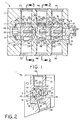
- a positive displacement pump 1 in accordance with this invention including three vane type pump units 2, 3 and 4 which share a common rotor shaft 5.
- the shaft 5 is mounted for rotation within a cylindrical bore 6 in a pump housing 7 as by means of a pair of sleeve bearings 8, 9 at opposite ends of the shaft.
- a retaining ring 10 At one end of the bore 6 is a retaining ring 10 to retain the various parts in assembled relation, whereas at the other end of the bore is a spring tension washer 11 that provides a desired preload on the various pump parts to maintain the desired fluid seal therebetween.
- Each of the pump units 2 through 4 includes its own set of vanes or blades 15, 16; 17, 18 and 19, 20 which extend through respective slots 21, 22; 23, 24 and 25, 26 in longitudinally spaced barrel portions 27, 28 and 29 of the rotor shaft 5.
- Surrounding the barrel portions 27, 28 and 29 are respective liners 30, 31 and 32.
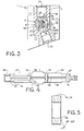
- the respective slots 21 through 26 and barrel portions 27 through 29 can best be seen in Fig. 4, which is a longitudinal section showing the rotor shaft 5 by itself.
- Each liner 30, 31 and 32 may be retained within the housing bore 6 as by means of a set screw 33 extending through a bore 34 in the housing wall 35 into an external recess 36 in each of the liners as schematically shown in Figs. 2 and 3.
- each pair of blades 15, 16; 17, 18 and 19, 20 may be formed as a single unit in a generally C-shape, with each pair facing in opposite directions in the respective slots as shown, or formed separately as desired.
- the size of the middle pump unit 3 is desirably selected using a conventional single pump unit per shaft design and standard journal size for that particular pump unit .
- the liner 31 for the middle pump unit 3 has an eccentric bore 40 whose axis is parallel to but offset with respect to the axis of the rotor shaft 5 as shown in Fig. 2, with the rotor barrel portion 28 as nearly tangent to the liner bore 40 as is practicable. Any clearance that does exist between the rotor barrel portion 28 and liner bore 40 is due to machining tolerances on the rotor shaft 5 and liner 31.
- the blade tips 41 for the middle pump unit 3 engage the liner bore 40 to define pockets 42 through 45 which expand and contract as the rotor shaft 5 rotates.
- the pockets move past the liner passages 46, 47 and associated ports 48, 49 in the pump housing 7, fluid is drawn in from one port and expelled out through the other port.
- the rotor shaft 5 is rotated in a clockwise direction as viewed in Fig. 2, the fluid will enter pump unit 3 through the port 48 and associated liner passage 46 and will be discharged from the pump under pressure through the liner passage 47 and associated housing port 49. Rotation of the rotor shaft 5 in the opposite direction will cause a reverse flow of fluid through the pump 3.
- Each of the other pump units 2, 4 operates in a similar manner.
- the rotor slots 21 through 26 for the respective pump units 2 through 4 are axially longer than the respective blades 15 through 20 which are substantially the same length as the respective liners 30 through 32.
- the middle pump unit 3 is separated from the two end pump units 3, 4 by spacers 54, 55 which are mounted on the rotor shaft 5 adjacent opposite ends of the barrel portion 28 of the middle pump unit 3 preferably using the standard journal size for that particular pump unit.
- the outer diameters of the journals 56, 57 for the two spacers 54, 55 are somewhat less than the outer diameter of the middle pump unit barrel portion 28 whereby the opposed end faces 58, 59 of the spacers 54, 55 radially overlap opposite ends of both the liner 31 and barrel portion 28, thus serving to position the blades 17, 18 axially within the slots 23, 24 even when the blades 17, 18 are in their radial innermost retracted positions.
- the blades 15, 16 and 19, 20 of the respective end pump units 2, 4 are positioned axially within the respective slots 21, 22 and 25, 26 (which are longer than the blades) by the spacers 54, 55 at one end and the end bearings 8, 9 at the opposite end.
- the barrel diameters 27, 29 for the two end pump units 2, 4 are made to correspond to the journal diameters 56, 57 for the middle pump unit 3.
- the liners 30, 32 for the two end pump units 2, 4 are sized such that the running clearance between the respective barrel portions 27, 29 and liner bores 60, 61 is substantially the same as for current conventional single pump unit per shaft designs, whereby the efficiency of the two end pump units 2, 4, like that of the middle pump unit 3, may be substantially the same as for current conventional single pump unit per shaft designs.
- the travel of the blades 15, 16 and 19, 20 in the respective liner bores 60, 61 of the two end pump units 2, 4, which are substantially identical, is such that the innermost retracted position of the blade tips 62 of the end pump units is very close to the inner diameter of the spacers 54, 55 (see Figs. 1 and 3).
- the blades 15, 16 and 19, 20 will protrude into the spacer inner diameters, causing interference.
- chamfers 65 are desirably provided on the inner diameters of the spacers 54, 55 on the ends facing the end pump units 2, 4 to guide the blade tips 61 out smoothly during outward movement of the blades 15, 16 and 19, 20 beyond their innermost retracted positions.
- the chamfers 65 on the spacers 54, 55 need only be provided in the regions of the innermost retracted positions of the blades 15, 16 and 19, 20 for the end pump units 2, 4.
- the chamfers 65 desirably extend all the way around the spacers at an angle of approximately 18 to 20° as measured from the end face of the spacers (see Fig. 5).
- the height of the chamfers 65 is desirably kept to a minimum size of between approximately 0.5 mm (0.020 inch) and 1.5 mm (0.060 inch) to restrict internal leakage.
- the diameter of the journals 66, 67 for the two end bearings 8, 9 is also preferably sized using the standard journal size for the two end pump units 2, 4, which is somewhat less than the barrel 27, 29 diameter for the two end pump units 2, 4 so that the end bearings 8, 9 serve to position the adjacent ends of the blades 15, 16 and 19, 20 within the slots 21, 22 and 25, 26 even when the blades are in the radial innermost retracted positions.
- the opposed ends of the end bearings 8, 9 as well as that of the spacers 54, 55 may be chamfered to accommodate inside corner radius on the rotor shaft 5.
- the two end pump units 2, 4 operate in substantially the same manner as the middle pump unit 3. That is, assuming as before that the shaft 5 is rotated in a clockwise direction as viewed in Fig. 3, fluid will enter pump unit 2 through housing port 70 and associated liner passage 71 and will be discharged from the pump under pressure through liner passage 72 and housing port 73. At the same time, fluid will enter pump unit 4 through housing port 74 and associated liner passage 75 and will be discharged from the pump under pressure through liner passage 76 and housing port 77 (see Fig. 1). Rotation of the shaft 5 in the opposite direction will cause a reverse flow through the two end pump units 2, 4.
Landscapes
- Engineering & Computer Science (AREA)
- Mechanical Engineering (AREA)
- General Engineering & Computer Science (AREA)
- Rotary Pumps (AREA)
- Reciprocating Pumps (AREA)
Claims (12)
- Pompe à déplacement positif à palettes comprenant un boîtier (7), un arbre (5) monté de sorte qu'il tourne dans ledit boîtier, une unité de pompe intermédiaire (3) à palettes et deux unités de pompe d'extrémité (2, 4) à palettes montées sur ledit arbre et espacées axialement par rapport à ladite unité de pompe intermédiaire placée en position intermédiaire entre lesdites unités de pompe d'extrémité, chaque dite unité de pompe (2, 3, 4) incluant une cavité (40, 60, 61) qui est placée dans ledit boîtier et qui a un axe parallèle à, et décalé de, l'axe dudit arbre et un jeu de palettes (15, 16, 17, 18, 19, 20) monté sur ledit arbre et coulissant radialement par rapport à celui-ci, lesdites palettes s'engageant avec les parois desdites cavités lorsque ledit arbre est en rotation, et un moyen de positionnement pour positionner axialement lesdites palettes dans lesdites cavités, ledit moyen de positionnement incluant des moyens d'espacement (54, 55) entre lesdites unités de pompe intermédiaire et d'extrémité, caractérisée en ce que ledit arbre (5) a des parties de tourillons (56, 57) de diamètre réduit adjacentes aux extrémités opposées de ladite cavité (40) pour ladite unité de pompe intermédiaire (3) et sur lesquelles sont montés lesdits moyens d'espacement (54, 55) pour positionner axialement lesdites palettes (17, 18) de ladite unité de pompe intermédiaire placée entre elles.
- La pompe de la revendication 1, dans laquelle ledit arbre (5) a une partie de cylindre (28) de plus grand diamètre placé entre lesdites parties de tourillons (56, 57) de diamètre réduit et entourée par une garniture (31) contenant ladite cavité (40) pour ladite unité de pompe de pompe (3), et chacun desdits moyens d'espacement (54, 55) chevauche radialement ladite partie de cylindre (28) de plus grand diamètre et ladite garniture (31) pour ladite unité de pompe intermédiaire.
- La pompe de la revendication 2, dans laquelle lesdites palettes (17, 18) pour ladite unité de pompe intermédiaire (3) sont admises dans des fentes longitudinales (23, 24) situées dans ladite partie de cylindre (28) de plus grand diamètre, et lesdites fentes (23, 24) sont plus longues que ladite partie de cylindre de plus grand diamètre et que lesdites palettes contenues dans lesdites fentes grâce à quoi lesdits moyens d'espacement (54, 55) servent à positionner lesdites palettes axialement à l'intérieur desdites fentes.
- La pompe d'une quelconque des revendications 1 à 3, où ledit arbre (5) inclut des parties de cylindres (27, 29) de diamètre réduit pour lesdites unités de pompe d'extrémité (2, 4) et dont le diamètre correspond au diamètre desdites parties de tourillons (56, 57) pour lesdits moyens d'espacement (54, 55).
- La pompe de la revendication 4, où lesdits moyens d'espacement (54, 55) positionnent également axialement lesdites palettes (15, 16, 19, 20) pour lesdites unités de pompe d'extrémité (2, 4) à une extrémité de chacune des dites cavités (60, 61) pour lesdites unités de pompe d'extrémité, et ledit moyen de positionnement inclut des paliers d'extrémité (8, 9) adjacents aux autres extrémités desdites cavités pour lesdites unités de pompe d'extrémité pour positionner axialement lesdites palettes (15, 16, 19, 20) pour lesdites unités de pompe d'extrémité auxdites autres extrémités.
- La pompe de la revendication 5, où ledit arbre (5) inclut des parties de tourillons supplémentaires (66, 67) adjacentes auxdites autres extrémités desdites cavités (60, 61) pour lesdites unités de pompe d'extrémité (2, 4) et sur lesquelles sont montés lesdits paliers d'extrémité (8, 9), et le diamètre extérieur desdites parties de tourillons supplémentaires (66, 67) est inférieur au diamètre extérieur desdites parties de cylindres (27, 29) pour lesdites pompes d'extrémité (2, 4).
- La pompe de la revendication 6, où lesdites parties de cylindres (27, 29) pour lesdites unités de pompe d'extrémité (2, 4) sont entourées de garnitures (30, 32) contenant lesdites cavités (60, 61) pour lesdites unités de pompe d'extrémité (2, 4), et lesdits paliers d'extrémité (8, 9) chevauchent radialement lesdites parties de cylindres (27, 29) et les garnitures (30, 32) pour lesdites unités de pompe d'extrémité.
- La pompe de la revendication 7, où lesdites palettes (15, 16, 19, 20) pour lesdites unités de pompe d'extrémité (2, 4) sont admises dans des fentes longitudinales (21, 22, 25, 26) qui (i) sont placées dans lesdites parties de cylindres (27, 29) pour lesdites unités de pompe d'extrémité et (ii) sont plus longues que lesdites palettes pour lesdites unités de pompe d'extrémité grâce à quoi lesdits moyens d'espacement (54, 55) et lesdits paliers d'extrémité (8, 9) servent à positionner lesdites palettes pour lesdites unités de pompe d'extrémité axialement à l'intérieur desdites fentes pour lesdites unités de pompe d'extrémité.
- La pompe d'une quelconque des revendications 4 à 8, où lesdites parties de cylindres (27, 29) pour lesdites unités de pompe d'extrémité (2, 4) sont montées sensiblement tangentiellement aux parois desdites cavités (60, 61) pour lesdites unités de pompe d'extrémité, et les diamètres intérieurs desdits moyens d'espacement (54, 55) ont des moyens de biseaux (65) sur les extrémités faisant face auxdites unités de pompe d'extrémité pour guider lesdites palettes (15, 16, 19, 20) pour lesdites unités de pompe d'extrémité doucement vers l'extérieur à partir de l'intérieur desdits diamètres intérieurs desdits moyens d'espacement pendant le mouvement vers l'extérieur desdites palettes pour lesdites unités de pompe d'extrémité au cas où lesdites palettes pour lesdites unités de pompe d'extrémité feraient saillie dans lesdits diamètres intérieurs desdits moyens d'espacement lorsqu'elles sont dans leur position la plus rétractée vers l'intérieur.
- La pompe de la revendication 9, où lesdits moyens de biseaux (65) s'étendent tout autour des diamètres intérieurs desdits moyens d'espacement (54, 55).
- La pompe de la revendication 9 ou 10, où lesdits moyens de biseaux (65) s'étendent en faisant un angle d'environ 18 à 20° mesuré à partir desdites extrémités desdits moyens d'espacement faisant face auxdites unités de pompe d'extrémité (2, 4) et ont une hauteur comprise entre 0,020 pouce et 0,060 pouce environ pour imiter la perte interne.
- La pompe d'une quelconque des revendications 9 à 11, où les diamètres intérieurs des autres extrémités desdits moyens d'espacement (54, 55) ont des moyens de biseaux supplémentaires pour faciliter le montage desdits moyens d'espacement sur ledit arbre (5).
Applications Claiming Priority (2)
| Application Number | Priority Date | Filing Date | Title |
|---|---|---|---|
| US07/467,786 US5037283A (en) | 1990-01-19 | 1990-01-19 | Vane type positive displacement pump having multiple pump units |
| US467786 | 1999-12-20 |
Publications (3)
| Publication Number | Publication Date |
|---|---|
| EP0437919A2 EP0437919A2 (fr) | 1991-07-24 |
| EP0437919A3 EP0437919A3 (en) | 1992-01-22 |
| EP0437919B1 true EP0437919B1 (fr) | 1995-01-04 |
Family
ID=23857174
Family Applications (1)
| Application Number | Title | Priority Date | Filing Date |
|---|---|---|---|
| EP90311094A Expired - Lifetime EP0437919B1 (fr) | 1990-01-19 | 1990-10-10 | Pompe à déplacement positif à palettes |
Country Status (5)
| Country | Link |
|---|---|
| US (1) | US5037283A (fr) |
| EP (1) | EP0437919B1 (fr) |
| JP (1) | JP2856897B2 (fr) |
| DE (1) | DE69015795T2 (fr) |
| ES (1) | ES2066150T3 (fr) |
Families Citing this family (14)
| Publication number | Priority date | Publication date | Assignee | Title |
|---|---|---|---|---|
| DE4222644C2 (de) * | 1992-07-10 | 1998-10-29 | Wilhelm Hoevecke | Als Motor oder Pumpe betreibbare Rotationsscheibenmaschine |
| DE4309318C2 (de) * | 1993-03-23 | 1995-10-12 | Steinheil Optronik Gmbh | Hydrostatische Pumpe |
| US5567140A (en) * | 1995-04-24 | 1996-10-22 | Itt Corporation | Keyed insert plate for curved rotary lobe pump chamber walls |
| FR2740512B1 (fr) * | 1995-10-25 | 1997-12-05 | Hispano Suiza Sa | Pompe a palettes formee d'unites alignees a rotor commun |
| DE19645586A1 (de) * | 1996-11-05 | 1998-05-07 | Zunhammer Sebastian | Rotationskolbenmaschine |
| US6923628B1 (en) * | 1998-09-30 | 2005-08-02 | Luk, Automobitechnik Gmbh | Vacuum pump |
| WO2004064992A1 (fr) * | 2003-01-20 | 2004-08-05 | De Jong Engineering Elburg B.V. | Diviseuse |
| US7048525B2 (en) * | 2003-07-23 | 2006-05-23 | J. E. Grote Company | Flow divider |
| US7393192B2 (en) * | 2004-03-25 | 2008-07-01 | Gregory P Wood | Rotary vane pump |
| DE202009013467U1 (de) * | 2009-10-06 | 2011-02-24 | Vemag Maschinenbau Gmbh | Füllstromteiler |
| US9057372B2 (en) | 2010-12-06 | 2015-06-16 | Hamilton Sundstrand Corporation | Gear root geometry for increased carryover volume |
| US20120171337A1 (en) * | 2011-01-05 | 2012-07-05 | AMF Automation Technologies, LLC d/b/a AMF Bakery Systems | Dough Portioner |
| US8807972B2 (en) | 2011-04-15 | 2014-08-19 | Hydro-Aire Inc. | Housingless positive displacement pump assembly |
| CA2890682A1 (fr) | 2012-11-16 | 2014-05-22 | Moog Inc. | Pompes a palettes et leurs procedes de commande |
Family Cites Families (7)
| Publication number | Priority date | Publication date | Assignee | Title |
|---|---|---|---|---|
| US949638A (en) * | 1909-02-10 | 1910-02-15 | Harry S Stormer | Motor for tube-cleaners. |
| US1165852A (en) * | 1914-10-28 | 1915-12-28 | Philip J Darlington | Rotary motor. |
| FR552792A (fr) * | 1922-06-13 | 1923-05-07 | Machine rotative universelle à palettes mobiles | |
| US2293119A (en) * | 1939-11-03 | 1942-08-18 | Walwin L Davis | Rotary pump |
| US2676545A (en) * | 1950-12-26 | 1954-04-27 | Lear Inc | Rotary pump having a viscositycontrolled by-pass |
| DE1203611B (de) * | 1957-04-15 | 1965-10-21 | Brakeshoe Internat S A | Regelbare Drehkolbenpumpe mit drei Rotoren |
| US4619594A (en) * | 1985-05-13 | 1986-10-28 | Lear Siegler, Inc. | Stackable rotary vane pump with improved volumetric efficiency |
-
1990
- 1990-01-19 US US07/467,786 patent/US5037283A/en not_active Expired - Lifetime
- 1990-10-10 DE DE69015795T patent/DE69015795T2/de not_active Expired - Fee Related
- 1990-10-10 ES ES90311094T patent/ES2066150T3/es not_active Expired - Lifetime
- 1990-10-10 EP EP90311094A patent/EP0437919B1/fr not_active Expired - Lifetime
- 1990-11-30 JP JP2330899A patent/JP2856897B2/ja not_active Expired - Fee Related
Also Published As
| Publication number | Publication date |
|---|---|
| EP0437919A3 (en) | 1992-01-22 |
| US5037283A (en) | 1991-08-06 |
| DE69015795T2 (de) | 1995-05-11 |
| JPH03217674A (ja) | 1991-09-25 |
| ES2066150T3 (es) | 1995-03-01 |
| JP2856897B2 (ja) | 1999-02-10 |
| EP0437919A2 (fr) | 1991-07-24 |
| DE69015795D1 (de) | 1995-02-16 |
Similar Documents
| Publication | Publication Date | Title |
|---|---|---|
| EP0437919B1 (fr) | Pompe à déplacement positif à palettes | |
| US6174151B1 (en) | Fluid energy transfer device | |
| US9732771B2 (en) | Hydraulic rotary actuator | |
| US6314642B1 (en) | Method of making an internal gear pump | |
| CN103842655A (zh) | 流体能量传递装置 | |
| US5507625A (en) | Liquid ring pumps | |
| EP0202816B1 (fr) | Pompe rotative à palettes, empilable à rendement volumétrique | |
| CA2807402A1 (fr) | Ensemble plateau d'equilibrage destine a un dispositif a fluide | |
| EP0542759B1 (fr) | Machine rotative a fluides pourvue de lobes a chambres multiples a etancheite parfaite obtenue par joints glissants | |
| US20230313793A1 (en) | Hydraulic machine | |
| SE0003075D0 (sv) | Vacuum pump | |
| EP0492348A1 (fr) | Méthode d'entraînement pour la soupape de distribution d'un moteur du type gerotor | |
| US20050042126A1 (en) | Vane type rotary machine | |
| US3444819A (en) | Hydraulic motors and pumps | |
| KR930007767B1 (ko) | 로터리 액츄에이터 | |
| US4875826A (en) | Pitot pump assembly for a rotating fluid management device | |
| US11519268B2 (en) | Rotary piston and cylinder device with flared curved rotor surface | |
| US3999903A (en) | Combination thrust and journal bearing | |
| JP3906318B2 (ja) | 容積形液圧機械 | |
| JPH1030730A (ja) | 非接触軸封装置 | |
| US4459091A (en) | Rotary vane pump | |
| IT9020911A1 (it) | Struttura di cuscinetto per supportare l'albero motore di un compressore centrifugo | |
| JPH0118868Y2 (fr) | ||
| US4948352A (en) | Rotor unit with peripheral projections and clearances for centrifugal deflection | |
| GB2118259A (en) | Alignment of bearing surfaces in two-part casings |
Legal Events
| Date | Code | Title | Description |
|---|---|---|---|
| PUAI | Public reference made under article 153(3) epc to a published international application that has entered the european phase |
Free format text: ORIGINAL CODE: 0009012 |
|
| AK | Designated contracting states |
Kind code of ref document: A2 Designated state(s): BE DE ES FR GB IT |
|
| PUAL | Search report despatched |
Free format text: ORIGINAL CODE: 0009013 |
|
| AK | Designated contracting states |
Kind code of ref document: A3 Designated state(s): BE DE ES FR GB IT |
|
| 17P | Request for examination filed |
Effective date: 19920624 |
|
| 17Q | First examination report despatched |
Effective date: 19930706 |
|
| GRAA | (expected) grant |
Free format text: ORIGINAL CODE: 0009210 |
|
| AK | Designated contracting states |
Kind code of ref document: B1 Designated state(s): BE DE ES FR GB IT |
|
| REF | Corresponds to: |
Ref document number: 69015795 Country of ref document: DE Date of ref document: 19950216 |
|
| ET | Fr: translation filed | ||
| REG | Reference to a national code |
Ref country code: ES Ref legal event code: FG2A Ref document number: 2066150 Country of ref document: ES Kind code of ref document: T3 |
|
| ITF | It: translation for a ep patent filed | ||
| PLBE | No opposition filed within time limit |
Free format text: ORIGINAL CODE: 0009261 |
|
| STAA | Information on the status of an ep patent application or granted ep patent |
Free format text: STATUS: NO OPPOSITION FILED WITHIN TIME LIMIT |
|
| 26N | No opposition filed | ||
| REG | Reference to a national code |
Ref country code: GB Ref legal event code: IF02 |
|
| PGFP | Annual fee paid to national office [announced via postgrant information from national office to epo] |
Ref country code: FR Payment date: 20020906 Year of fee payment: 13 |
|
| PGFP | Annual fee paid to national office [announced via postgrant information from national office to epo] |
Ref country code: GB Payment date: 20020916 Year of fee payment: 13 |
|
| PGFP | Annual fee paid to national office [announced via postgrant information from national office to epo] |
Ref country code: DE Payment date: 20020924 Year of fee payment: 13 |
|
| PGFP | Annual fee paid to national office [announced via postgrant information from national office to epo] |
Ref country code: ES Payment date: 20021007 Year of fee payment: 13 |
|
| PGFP | Annual fee paid to national office [announced via postgrant information from national office to epo] |
Ref country code: BE Payment date: 20021016 Year of fee payment: 13 |
|
| PG25 | Lapsed in a contracting state [announced via postgrant information from national office to epo] |
Ref country code: GB Free format text: LAPSE BECAUSE OF NON-PAYMENT OF DUE FEES Effective date: 20031010 |
|
| PG25 | Lapsed in a contracting state [announced via postgrant information from national office to epo] |
Ref country code: ES Free format text: LAPSE BECAUSE OF NON-PAYMENT OF DUE FEES Effective date: 20031011 |
|
| PG25 | Lapsed in a contracting state [announced via postgrant information from national office to epo] |
Ref country code: BE Free format text: LAPSE BECAUSE OF NON-PAYMENT OF DUE FEES Effective date: 20031031 |
|
| BERE | Be: lapsed |
Owner name: *LEAR ROMEC CORP. Effective date: 20031031 |
|
| PG25 | Lapsed in a contracting state [announced via postgrant information from national office to epo] |
Ref country code: DE Free format text: LAPSE BECAUSE OF NON-PAYMENT OF DUE FEES Effective date: 20040501 |
|
| GBPC | Gb: european patent ceased through non-payment of renewal fee |
Effective date: 20031010 |
|
| PG25 | Lapsed in a contracting state [announced via postgrant information from national office to epo] |
Ref country code: FR Free format text: LAPSE BECAUSE OF NON-PAYMENT OF DUE FEES Effective date: 20040630 |
|
| REG | Reference to a national code |
Ref country code: FR Ref legal event code: ST |
|
| REG | Reference to a national code |
Ref country code: ES Ref legal event code: FD2A Effective date: 20031011 |
|
| PG25 | Lapsed in a contracting state [announced via postgrant information from national office to epo] |
Ref country code: IT Free format text: LAPSE BECAUSE OF NON-PAYMENT OF DUE FEES;WARNING: LAPSES OF ITALIAN PATENTS WITH EFFECTIVE DATE BEFORE 2007 MAY HAVE OCCURRED AT ANY TIME BEFORE 2007. THE CORRECT EFFECTIVE DATE MAY BE DIFFERENT FROM THE ONE RECORDED. Effective date: 20051010 |