EP0438067A2 - Stempel mit automatischer Einfärbvorrichtung - Google Patents
Stempel mit automatischer Einfärbvorrichtung Download PDFInfo
- Publication number
- EP0438067A2 EP0438067A2 EP91100183A EP91100183A EP0438067A2 EP 0438067 A2 EP0438067 A2 EP 0438067A2 EP 91100183 A EP91100183 A EP 91100183A EP 91100183 A EP91100183 A EP 91100183A EP 0438067 A2 EP0438067 A2 EP 0438067A2
- Authority
- EP
- European Patent Office
- Prior art keywords
- housing
- cap
- stamp
- ink pad
- spring means
- Prior art date
- Legal status (The legal status is an assumption and is not a legal conclusion. Google has not performed a legal analysis and makes no representation as to the accuracy of the status listed.)
- Granted
Links
Images

Classifications
-
- B—PERFORMING OPERATIONS; TRANSPORTING
- B41—PRINTING; LINING MACHINES; TYPEWRITERS; STAMPS
- B41K—STAMPS; STAMPING OR NUMBERING APPARATUS OR DEVICES
- B41K1/00—Portable hand-operated devices without means for supporting or locating the articles to be stamped, i.e. hand stamps; Inking devices or other accessories therefor
- B41K1/36—Details
- B41K1/38—Inking devices; Stamping surfaces
- B41K1/40—Inking devices operated by stamping movement
- B41K1/42—Inking devices operated by stamping movement with pads or rollers movable for inking
Definitions
- This invention relates to hand stamping devices for making ink impressions on documents, boxes or other surfaces where the printing die automatically moves from a position against an ink pad to a printing position when the stamp is pressed downward on to the surface to be imprinted. More specifically, a stamper is disclosed that can be more compact and which affords easy mess-free removal of the ink pad when replacement becomes necessary.
- Self-inking stamps are known in the prior art that operate by pressing an outer housing downward so it slides down and around an inner housing.
- the inner housing contains a rotatable printing die that moves from a rest position against an ink pad to an imprint position in response to the relative movement of the inner and outer housings.
- the inner and outer housing are spring biased apart so as to hold the die normally against the ink pad when the stamp is not being compressed.
- the outer housing includes a metal bridge that spans the housing and against which are mounted the springs that engage and bias the inner housing towards a rest position.
- the bias springs necessarily rest against the ink pad itself.
- a cap on the outer housing is removed to expose the metal bridge.
- the hand stamp is then compressed, and held that way, so as to bring the ink pad closer to the metal bridge whereby ink can be dispensed through holes in the bridge, and actually through the centers of the spring, into ink wells that communicate via small holes with actual ink pad.
- a slight misjudgment by the user can create messy ink spills throughout the complicated mechanism. Worse yet, if the compressed stamper is accidentally released, ink may splatter everywhere. A more efficient, easier to use, cleaner, and more compact design is contemplated by the present invention.
- the instant invention provides an improved design that avoids the need to introduce fluid ink into the hand stamper.
- a removable ink pad containing box is employed which when exhausted may be removed totally and replaced with a fresh ink pad box. There is no need to pour ink into the hand stamper itself.
- Another improvement in design is that the bias springs are mounted directly to the outer housing cap so that when the cap is removed, the springs go with it, thus exposing the removable ink pad box for easy removal. Special mounts are provided between the spring and cap, and also between the cap and outer housing so that the cap can be conveniently snapped on and off the housing and still contain the bias spring forces which forces are communicated from the inner housing to the outer housing by means of the cap alone.
- Springs mounted in this way make use of the full internal space in the outer housing, extending from the ink pad box all the way to the cap so as to provide additional synergistic benefits in the form of longer springs and more compact housings.
- Longer springs give smoother spring action and a more even and repeatable pressure of the printing die on the ink pad.
- the quality of the printed image is dependent on the correct pressure of the die on the ink pad.
- a more compact structure is desirable to save on materials and when smaller stampers are desired.
- a stamper is provided that has less parts, eliminating a metal spring supporting bridge, and which is cleaner in use, more compact, and more reliable. Providing fresh ink pads in easier, faster and less messy than in the prior art. Additional advantages, features, and improvements will become apparent upon consideration of the following detailed description and drawings.
- Figure 1 is a cross-sectional elevational view of the hand stamp of the present invention showing the essential operating components and the relationship of the inner and outer housings.
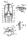
- Figure 2 is also a cross-sectional elevational view of the stamp, but taken from the side view relative to Figure 1.
- Figure 3 is a fragmentary detail view of the area of the cap where the bias springs are attached so as to be removable with the cap.
- Figure 4 and 5 show, respectively, two orthogonal views of a typical latch or mount to secure the cap to the outer housing and resist spring bias forces.
- Figure 6 shows the hand stamper with the inner housing in the extended rest position as assumed when the bias springs are fully extended.
- Figure 7 shows how the cap and bias springs may be detached as a unit and the inner housing positioned to permit easy clean removal of the replaceable ink pad box.
- an outer housing 10 which surrounds and partially contains within it a vertically slidable inner housing 12.
- both housings comprise generally rectangular and hollow members, open at the bottom, and similar in size.
- the outer housing 10 is grasped with the hand and pressed downward pushing the open lower end of inner housing 12 against the surface to be imprinted.
- This causes inner housing 12 to slide upward inside housing 10, against the action of a pair of biasing springs 14 and 16, and also causes a rotary die pad 18, and a die 20 mounted thereon, to both move downward relative to inner housing 12 and to rotate during that downward movement.
- die pad 18 is pivotally mounted about an axle 22 by means of two downwardly extending guides 26 and 28 through which axle 22 passes. Since axle 22 is mounted at its ends in holes 30 and 32 in outer housing 10, it moves downward with housing 10 and carries die pad 18 downward inside housing 12 as well. Slots in housing 12 allow the downward slide of axle 22.
- the rotary motion of die pad 18 is induced by a pair of slotted guide plates 34 and 36 which have pins 38 and 40 about which guides 26 and 28 pivot.
- the slotted guide plates themselves can swing about two other pins 35 which engage housing 12.
- the slotted guide plates 34 and 36 both contain a curved slot 42.
- guides 26 and 28 both contain a groove 44 that engages pins 38 and 40.
- axle 22 moves downward, it slides along curved slots 42 causing guides 26 and 28, and the attached die 20, to rotate about pins 38 and 40 so as to bring die 20 through a half turn whereby it emerges from the open lower end of inner housing 12 and imprints the surface upon which housing 12 is resting.
- This downward rotary movement of the impression die is similar to mechanisms in the art and not of particular concern in the instant disclosure.
- ink pad 46 ink pad 46 in contained in a removable ink pad box 48 that snaps in by a friction fit onto ledges 50 in housing 12.
- a pair of spring retaining cups 52 and 53 are formed on the top of ink pad box 48 to locate and axially restrain bias springs 14 and 16. Cup 53 is shown in section in Figure 1.
- Housing 10 includes a snap-on cap 54 to which the upper ends of springs 14 and 16 are firmly attached.
- Figure 3 shows a possible attaching structure wherein lugs 56 and 57 extend through the center and under the upper portions of the bias springs.
- Removable ink pad 48 may now be easily snapped out and replaced.
- Spring cups 53 and 52 afford convenient gripping surfaces to facilitate this replacement. The whole ink pad may be discarded and a new one inserted with no messy ink bottles to handle, and no obstructing bias spring mechanism to block the way.
- FIG. 4 and 5 show suitable mounting structures wherein a hook shaped lug 60 on cap 54 snaps under and engages a strap or loop 62 formed as a part of housing 10.
- the combination of this lug and strap comprises a mount assembly 64 shown only schematically in Figure 2. Four such assemblies 64 are contemplated in the preferred embodiment, although, of course, many variations are possible.
Landscapes
- Ink Jet (AREA)
- Pens And Brushes (AREA)
- Closures For Containers (AREA)
Applications Claiming Priority (2)
| Application Number | Priority Date | Filing Date | Title |
|---|---|---|---|
| US462724 | 1983-01-31 | ||
| US07/462,724 US4970954A (en) | 1990-01-09 | 1990-01-09 | Self inking hand stamp |
Publications (3)
| Publication Number | Publication Date |
|---|---|
| EP0438067A2 true EP0438067A2 (de) | 1991-07-24 |
| EP0438067A3 EP0438067A3 (en) | 1991-09-11 |
| EP0438067B1 EP0438067B1 (de) | 1995-10-18 |
Family
ID=23837535
Family Applications (1)
| Application Number | Title | Priority Date | Filing Date |
|---|---|---|---|
| EP91100183A Expired - Lifetime EP0438067B1 (de) | 1990-01-09 | 1991-01-08 | Stempel mit automatischer Einfärbvorrichtung |
Country Status (3)
| Country | Link |
|---|---|
| US (1) | US4970954A (de) |
| EP (1) | EP0438067B1 (de) |
| DE (1) | DE69113820T2 (de) |
Cited By (4)
| Publication number | Priority date | Publication date | Assignee | Title |
|---|---|---|---|---|
| US6058840A (en) * | 1995-12-18 | 2000-05-09 | Zaklad Mechaniczny "Wagraf" | Stamp mounting |
| WO2004082949A1 (de) | 2003-03-18 | 2004-09-30 | Colop Stempelerzeugung Skopek Gesellschaft M.B.H. & Co. Kg. | Selbstfärbestempel mit oberschlagfärbung und farbkissen-behälter hiefür |
| WO2004082950A1 (de) | 2003-03-18 | 2004-09-30 | Colop Stempelerzeugung Skopek Gesellschaft M.B.H. & Co. Kg. | Selbstfärbestempel mit oberschlagfärbung sowie farbkissen-behälter hiefür |
| RU2237580C2 (ru) * | 2000-05-11 | 2004-10-10 | Тродат Гмбх | Самоокрашивающийся штемпель |
Families Citing this family (42)
| Publication number | Priority date | Publication date | Assignee | Title |
|---|---|---|---|---|
| USD323527S (en) | 1990-01-09 | 1992-01-28 | Porelon, Inc. | Self-inking hand stamp |
| USD333675S (en) | 1990-05-14 | 1993-03-02 | Chiovitti Angelo M | Printing head |
| US5517916A (en) * | 1994-09-14 | 1996-05-21 | M&R Marking Systems, Inc. | Self-inking stamp |
| USD367290S (en) | 1994-10-24 | 1996-02-20 | M&R Marking Systems, Inc. | Self-inking stamp |
| US5623875A (en) * | 1996-03-28 | 1997-04-29 | Perets; Mishel | Multi-color and easy to assemble automatic rubber stamp |
| US5768992A (en) * | 1996-05-24 | 1998-06-23 | M&R Marking Systems, Inc. | Hand stamp and method of assembling same |
| US6948257B1 (en) * | 1998-02-27 | 2005-09-27 | Barr Jr William A | Marking device with self-hinged contact plate and marking members |
| US7334342B1 (en) | 1998-02-27 | 2008-02-26 | William Ack Barr | Marking device having marking members |
| AT409742B (de) * | 2001-01-25 | 2002-10-25 | Trodat Gmbh | Farbkissen für einen selbstfärbestempel |
| AT409741B (de) * | 2001-01-25 | 2002-10-25 | Trodat Gmbh | Selbstfärbestempel |
| USD492957S1 (en) | 2003-09-23 | 2004-07-13 | Sun Coast Merchandise Corp. | Hand stamp |
| US6931990B2 (en) * | 2003-09-26 | 2005-08-23 | Sun Coast Merchandise Corp. | Stamper |
| EP1762259B2 (de) * | 2005-09-12 | 2025-01-01 | Unomedical A/S | Einfürungssystem für ein Infusionsset mit einem ersten und zweiten Federeinheit |
| PL1962925T3 (pl) | 2005-12-23 | 2009-10-30 | Unomedical As | Urządzenie do podawania |
| CA2642415A1 (en) | 2006-02-28 | 2007-09-07 | Unomedical A/S | Inserter for infusion part and infusion part provided with needle protector |
| WO2007140785A1 (en) | 2006-06-09 | 2007-12-13 | Unomedical A/S | Mounting pad |
| CA2658577A1 (en) * | 2006-08-02 | 2008-02-07 | Unomedical A/S | Cannula and delivery device |
| US20100004597A1 (en) * | 2006-08-02 | 2010-01-07 | Unomedical A/S | Insertion Device |
| WO2008092782A1 (en) * | 2007-02-02 | 2008-08-07 | Unomedical A/S | Injection site for injecting medication |
| AU2008266382B2 (en) | 2007-06-20 | 2013-06-27 | Unomedical A/S | A catheter and a method and an apparatus for making such catheter |
| JP2010531692A (ja) * | 2007-07-03 | 2010-09-30 | ウノメディカル アクティーゼルスカブ | 双安定均衡状態を持つ挿入器 |
| JP2011509097A (ja) | 2007-07-10 | 2011-03-24 | ウノメディカル アクティーゼルスカブ | 2つのスプリングを備えた挿入器 |
| CA2694952A1 (en) * | 2007-07-18 | 2009-01-22 | Unomedical A/S | Insertion device with pivoting action |
| US20110098652A1 (en) * | 2008-02-13 | 2011-04-28 | Unomedical A/S | Moulded Connection between Cannula and Delivery Part |
| PL2252349T3 (pl) | 2008-02-13 | 2012-01-31 | Unomedical As | Uszczelnienie między częścią kaniulową a drogą przepływu płynu |
| CA2715667A1 (en) | 2008-02-20 | 2009-08-27 | Unomedical A/S | Insertion device with horizontally moving part |
| US20110168294A1 (en) * | 2008-05-30 | 2011-07-14 | Claus Jakobsen | Reservoir filling device |
| CN102256657A (zh) | 2008-12-22 | 2011-11-23 | 犹诺医药有限公司 | 包括粘合垫的医疗器械 |
| AU2010277755A1 (en) | 2009-07-30 | 2012-02-02 | Unomedical A/S | Inserter device with horizontal moving part |
| MX2012000778A (es) | 2009-08-07 | 2012-07-30 | Unomedical As | Dispositivo de suministro con sensor y una o mas canulas. |
| MX2012011085A (es) | 2010-03-30 | 2012-10-10 | Unomedical As | Dispositivo medico. |
| EP2433663A1 (de) | 2010-09-27 | 2012-03-28 | Unomedical A/S | Einführsystem |
| EP2436412A1 (de) | 2010-10-04 | 2012-04-04 | Unomedical A/S | Sprinklerkanüle |
| WO2013050277A1 (en) | 2011-10-05 | 2013-04-11 | Unomedical A/S | Inserter for simultaneous insertion of multiple transcutaneous parts |
| EP2583715A1 (de) | 2011-10-19 | 2013-04-24 | Unomedical A/S | Infusionsschlauchsystem und Herstellungsverfahren |
| US9440051B2 (en) | 2011-10-27 | 2016-09-13 | Unomedical A/S | Inserter for a multiplicity of subcutaneous parts |
| USD732106S1 (en) * | 2013-01-24 | 2015-06-16 | Colop Stempelerzeugung Skopek Gmbh & Co. Kg. | Self-inking stamp |
| JP1519095S (de) * | 2014-09-16 | 2015-03-16 | ||
| US11324948B2 (en) * | 2015-07-21 | 2022-05-10 | Koninklijke Philips N.V. | Device for radio-frequency skin treatment |
| CN105485105B (zh) * | 2016-01-22 | 2018-02-02 | 深圳利亚德光电有限公司 | 连接结构及具有其的led显示装置 |
| JP6870319B2 (ja) * | 2016-12-26 | 2021-05-12 | シヤチハタ株式会社 | 反転式印判 |
| KR102413170B1 (ko) * | 2020-07-29 | 2022-06-23 | 서광석 | 볼트 마킹용 스탬프 |
Family Cites Families (4)
| Publication number | Priority date | Publication date | Assignee | Title |
|---|---|---|---|---|
| US3033112A (en) * | 1960-01-08 | 1962-05-08 | Bill D Cleveland | Dispensing handle |
| US3364856A (en) * | 1965-11-22 | 1968-01-23 | Cubic Corp | Marking device having a pad inker and tumbler bed |
| US4432281A (en) * | 1982-03-10 | 1984-02-21 | M & R Seal Press Co., Inc. | Self-inking stamping device |
| US4852489A (en) * | 1987-11-18 | 1989-08-01 | M&R Marking Systems, Inc. | Self-inking stamping device |
-
1990
- 1990-01-09 US US07/462,724 patent/US4970954A/en not_active Expired - Lifetime
-
1991
- 1991-01-08 DE DE69113820T patent/DE69113820T2/de not_active Expired - Fee Related
- 1991-01-08 EP EP91100183A patent/EP0438067B1/de not_active Expired - Lifetime
Cited By (7)
| Publication number | Priority date | Publication date | Assignee | Title |
|---|---|---|---|---|
| US6058840A (en) * | 1995-12-18 | 2000-05-09 | Zaklad Mechaniczny "Wagraf" | Stamp mounting |
| RU2237580C2 (ru) * | 2000-05-11 | 2004-10-10 | Тродат Гмбх | Самоокрашивающийся штемпель |
| WO2004082949A1 (de) | 2003-03-18 | 2004-09-30 | Colop Stempelerzeugung Skopek Gesellschaft M.B.H. & Co. Kg. | Selbstfärbestempel mit oberschlagfärbung und farbkissen-behälter hiefür |
| WO2004082950A1 (de) | 2003-03-18 | 2004-09-30 | Colop Stempelerzeugung Skopek Gesellschaft M.B.H. & Co. Kg. | Selbstfärbestempel mit oberschlagfärbung sowie farbkissen-behälter hiefür |
| US7380497B2 (en) | 2003-03-18 | 2008-06-03 | Colop Stempelerzeugung Skopek Gesellschaft m.b.H. & Co. KG | Self-inking stamp with ink pad container having snap-in engagement with stamp housing |
| US7389727B2 (en) | 2003-03-18 | 2008-06-24 | Colop Stempelerzeugung Skopek Gesellschaft m.b.H. & Co. KG | Self-inking stamp having ink pad container with recesses engaging guiding and centering projections on housing sidewalls |
| US7677172B2 (en) | 2003-03-18 | 2010-03-16 | Colop Stempelerzeugung Skopek Gesellschaft M.B.H. & Co. Kg. | Ink pad container for a self-inking stamp |
Also Published As
| Publication number | Publication date |
|---|---|
| EP0438067B1 (de) | 1995-10-18 |
| US4970954A (en) | 1990-11-20 |
| EP0438067A3 (en) | 1991-09-11 |
| DE69113820D1 (de) | 1995-11-23 |
| DE69113820T2 (de) | 1996-03-21 |
Similar Documents
| Publication | Publication Date | Title |
|---|---|---|
| US4970954A (en) | Self inking hand stamp | |
| CA1138712A (en) | Rubber stamp | |
| US3832947A (en) | Simplified, self-inking hand stamp | |
| US2819668A (en) | Hand stamp | |
| US4432281A (en) | Self-inking stamping device | |
| US5649485A (en) | Self-inking stamp | |
| US4852489A (en) | Self-inking stamping device | |
| EP1322477B1 (de) | Handstempel und verfahren zum zusammenbau des handstempels | |
| US5111745A (en) | Ink stamps | |
| HRP950582A2 (en) | Stamping device | |
| CN100478187C (zh) | 手动印章及用于手动印章的顶帽 | |
| US5014617A (en) | Self-storing and inking stamp | |
| US4579057A (en) | Stamper with rotatable cover | |
| US4152984A (en) | Inking mechanism for printing apparatus | |
| EP0803372B1 (de) | Selbstfärbestempel | |
| CA1158095A (en) | Product name stamping device of label printers | |
| PL358208A1 (en) | Self-inking stamp | |
| JP2003505283A (ja) | ハンドスタンプ | |
| US5048414A (en) | Automatic stamper | |
| EP1948449A1 (de) | Stempelkissenhalter für selbstfärbestempel | |
| US4411196A (en) | Imprinter with locking and releasing device | |
| GB2236981A (en) | Adjustable ink stamp | |
| JP2578125Y2 (ja) | 捺印具 | |
| GB2157626A (en) | Die stamping assemblies | |
| JPH0719813Y2 (ja) | 押 印 |
Legal Events
| Date | Code | Title | Description |
|---|---|---|---|
| PUAI | Public reference made under article 153(3) epc to a published international application that has entered the european phase |
Free format text: ORIGINAL CODE: 0009012 |
|
| PUAL | Search report despatched |
Free format text: ORIGINAL CODE: 0009013 |
|
| 17P | Request for examination filed |
Effective date: 19910128 |
|
| AK | Designated contracting states |
Kind code of ref document: A2 Designated state(s): DE FR GB |
|
| AK | Designated contracting states |
Kind code of ref document: A3 Designated state(s): DE FR GB |
|
| 17Q | First examination report despatched |
Effective date: 19931105 |
|
| GRAA | (expected) grant |
Free format text: ORIGINAL CODE: 0009210 |
|
| AK | Designated contracting states |
Kind code of ref document: B1 Designated state(s): DE FR GB |
|
| REF | Corresponds to: |
Ref document number: 69113820 Country of ref document: DE Date of ref document: 19951123 |
|
| ET | Fr: translation filed | ||
| PG25 | Lapsed in a contracting state [announced via postgrant information from national office to epo] |
Ref country code: GB Effective date: 19960118 |
|
| PLBE | No opposition filed within time limit |
Free format text: ORIGINAL CODE: 0009261 |
|
| STAA | Information on the status of an ep patent application or granted ep patent |
Free format text: STATUS: NO OPPOSITION FILED WITHIN TIME LIMIT |
|
| GBPC | Gb: european patent ceased through non-payment of renewal fee |
Effective date: 19960118 |
|
| PG25 | Lapsed in a contracting state [announced via postgrant information from national office to epo] |
Ref country code: FR Effective date: 19960930 |
|
| PG25 | Lapsed in a contracting state [announced via postgrant information from national office to epo] |
Ref country code: DE Effective date: 19961001 |
|
| 26N | No opposition filed | ||
| REG | Reference to a national code |
Ref country code: FR Ref legal event code: ST |