EP0438175A2 - Collecteur de bulles rempli de matériau granulaire - Google Patents
Collecteur de bulles rempli de matériau granulaire Download PDFInfo
- Publication number
- EP0438175A2 EP0438175A2 EP91100593A EP91100593A EP0438175A2 EP 0438175 A2 EP0438175 A2 EP 0438175A2 EP 91100593 A EP91100593 A EP 91100593A EP 91100593 A EP91100593 A EP 91100593A EP 0438175 A2 EP0438175 A2 EP 0438175A2
- Authority
- EP
- European Patent Office
- Prior art keywords
- container
- projectile
- trap according
- projectile trap
- projectiles
- Prior art date
- Legal status (The legal status is an assumption and is not a legal conclusion. Google has not performed a legal analysis and makes no representation as to the accuracy of the status listed.)
- Withdrawn
Links
Images


Classifications
-
- F—MECHANICAL ENGINEERING; LIGHTING; HEATING; WEAPONS; BLASTING
- F41—WEAPONS
- F41J—TARGETS; TARGET RANGES; BULLET CATCHERS
- F41J13/00—Bullet catchers
Definitions
- the invention relates to a bullet trap according to the preamble of claim 1.
- DE-PS 31 31 228.4 shows a bullet trap in which, behind a target surface, a plurality of vertically arranged plates are spaced apart in two rows in a row such that zigzag channels are formed between the plates of the two rows where the incoming projectiles swing back and forth until they are braked so far that they fall down onto the floor under the bullet trap.
- DE-OS 32 12 781 another bullet trap emerges, in which a granulate bound by a binding agent to form a lump-like structure is arranged, the task of which is also to slow down the projectiles discharged into the granulate.
- a problem with the known granular projectile catch is that disposal of the projectile catch is problematic is because the projectiles released into the bound granulate are held in it, that is to say are part of the bound granulate. This means that disposal can only take place by disposing of the bound granules together with the projectiles contained therein. This means that the amount of disposal incurred per operating period of projectile capture is relatively large. In addition, a separation of the bound granulate and the floors contained therein is hardly possible or only with extremely complex steps.
- the object of the present invention is therefore to improve a bullet trap of the type mentioned in such a way that a much easier and better disposal is made possible.
- the main advantage of the projectile trap according to the invention is that simple disposal of the projectile trap is possible.
- the granulate and the braked projectiles contained therein are extremely simple and effective Are separable from each other. This has the consequence that the projectiles or projectile particles braked in the projectile trap can simply be recovered and disposed of or further processed, and at the same time the granules in the projectile trap can be used as a braking medium.
- the operating costs of the bullet trap according to the invention are reduced to a very substantial extent because the granulate used as the braking medium can be reused and because only small amounts of disposal, namely the bullets braked in the bullet trap, are incurred.
- projectile catch can be designed for any type of ammunition.
- only the length of the bullet catch in the weft direction is adapted to the type of caliber used.
- a length of approximately 400 mm is selected for handguns, while a projectile catch suitable for long weapons is approximately 800 mm long.
- the bullet trap according to the invention can advantageously can be built in any size depending on the application.
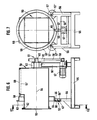
- the present granular projectile trap essentially has a preferably box-shaped container 1, which is on one, behind one Side arranged target surface has a recess 11 which is closed by a preferably disc-shaped medium 2 through which the projectiles fired at the target surface can pass.
- the medium 2 is preferably a rubber plate. Due to the elasticity of the rubber material, the holes formed in the rubber sheet 2 when the projectiles penetrate close again automatically when the projectiles have passed through the rubber sheet 2.
- the rubber plate 2 is preferably stretched in front of the recess 11 so that it closes the recess 11 like a wall.
- the granulate 3 which is generally a granular, free-flowing soft material that is capable of closing the length L (FIG. 2) of the container 1 released into the container 1 by the rubber plate 2 slow down.
- the granulate 3 preferably consists of granular rubber material, the grain size of which is, for example, about 6 mm and which is available on the market as a waste product.
- the container 1 can have a removal opening, for example the tubular opening 4 in FIG. 1, and a filling opening (not shown in more detail), for example in the upper container wall.
- the removed granules containing the projectile particles can be freed from the projectiles or projectile particles in a simple manner known per se. Procedures for this will be explained in more detail later.
- the container is box-shaped, wherein the rubber plate 2 forms the front wall of the container 1 'and closes the opening 11' formed by the side walls, the upper wall and the lower wall.
- the container On the side facing away from the rubber plate 2, the container is closed by a rear wall.
- the lower wall of the container extends obliquely downwards from the lower end of the rear wall in the direction of the rubber plate 2, so that the lowest point of the container is approximately where the lower wall and the rubber plate 2 meet. In this area there is preferably a removal opening 4 'for the granulate.
- a removal opening 4 "is preferably arranged there. 1 and 2 is also box-shaped, the lower wall of the container 1 being in the form of a funnel, the upper opening of which is molded onto the walls of the container and the lower end of which forms the outlet opening 4.
- the outlet openings 4, 4 'or 4 are preferably each formed by a pipe socket attached to the container 1, 1', 1", which can be closed by a cover or the like.
- the rubber plate 2 of the container 1, 1 ', 1 can be arranged behind a target surface or can even form the target surface.
- the outer surface of the rubber plate 2 can be coated with a white material, so that it can serve as a projection surface for stationary or moving target images generated with the aid of a suitable projector.
- the granules are removed from the container 1, 1 ', 1 "for disposal of the bombarded granules and carried out at a location separate from the projectile trap.
- the removal opening 4 is connected via a valve 5 to the inlet 6 of a separating device 7, which has a first outlet, which is connected to a line 9, and a second outlet 8.
- the granular granules 3 are separated from the projectile particles, the projectile particles being discharged via the outlet 8 and the granules being returned to the container 1 via the return line 9 and an opening 10 in a wall of the container 1.
- the separating device 7 is such that it can suck the granules and the bullet trapping parts out of the container 1 via the opened valve 5, a separation being carried out in the separating device 7 due to the different weights of the granules 3 and the projectile particles such that the comparatively heavy projectile particles are fed to the outlet 8 and the comparatively light granules to the return line 9.
- the separating device 7 can be a centrifuge device or a vacuum separator in which the parts sucked in via the opened valve 5 by a vacuum generated are separated in such a way that the heavier particles are fed to the outlet 8 and the lighter particles are sucked back via line 9 to container 1.
- the corresponding vacuum pump can be provided either in the separating device 7 or at the opening 10 of the return line 9 in the container 1 or in the return line 9. However, it is also conceivable to reintroduce the granulate parts separated from the projectile particles in the separating device 7 into the container 1 under pressure via the return line 9.
- the separation in the separation device 7 can also be carried out by the jet of a fan, which feeds the light particles to the return line 9 and allows the heavy particles to pass to the outlet 8. It is conceivable to use sensors that control the beam depending on the type of particles detected (granules or projectiles or projectile particles).
- a large projectile area which may for example comprise 4x8 m, is formed by a container 1 "', the access opening or recess 11"' of which corresponds to the size of the projectile area.
- a container 1 "' the access opening or recess 11"' of which corresponds to the size of the projectile area.
- Each extraction point is connected via a valve 41, 42, 43 to a collecting line 9 ′′ for the removed granulate, which contains the projectiles and projectile particles.
- the collecting line 9 ′ is connected to a separating device 7 ′, which has an outlet 8 ′ for the projectiles and projectile particles and a further outlet which is connected to a return line 9 'which is led into the interior of the container 1 "'. Since the provision of a rubber plate covering the large recess 11 "'is relatively complex, the recess 11"' is preferably covered by a plurality of rubber plates 2 'arranged next to one another, which either adjoin one another or can overlap in the manner shown.
- Disposal of this projectile catch can advantageously be individually adapted to the areas of the projectile catch used more or less during a predetermined operating time, since the individual valves 41, 42, 43 are opened separately from one another depending on the respective load on the areas of the granules 3 assigned to them with projectile catch particles can be.
- the walls of the container 1, 1 ', 1'',1''' are preferably made of steel. However, it is also conceivable that these walls at least partially by z. B. existing concrete walls are formed.
- FIGS. 6 and 7 show a further development of the invention, in which the container 50 of the projectile catch can be set in motion by a device 51 in such a way that the contents of the container 50, that is to say the bombarded granulate, are set in motion to avoid clumping of the granules and to ensure that the bullets released into the granules are moved out of the main bullet area, so that collisions between bullets which have already slowed down in the granules and newly penetrating bullets are avoided.
- the container 50 of the projectile catch can be set in motion by a device 51 in such a way that the contents of the container 50, that is to say the bombarded granulate, are set in motion to avoid clumping of the granules and to ensure that the bullets released into the granules are moved out of the main bullet area, so that collisions between bullets which have already slowed down in the granules and newly penetrating bullets are avoided.
- the device 51 is designed such that it can rotate the container 50 about its longitudinal axis 54. During these rotations, clumping of the granules 51 'is prevented and, in addition, the projectiles or projectile particles located in the granules 51' are led out of the injection area located behind the injection opening 52.
- the bullet opening 52 is closed by a penetrable medium 53, for example by a rubber plate.
- the rotation of the container 50 about the longitudinal axis 54 is effected in that the container 50 in a frame, which preferably consists of a base plate 55 and a plurality of them projecting vertically upwards Stand parts 56 ', 56 "is formed so as to be rotatable about the longitudinal axis 54.
- two spaced stand parts 56" are provided on one side of the base plate 55, the free ends of which each have a roller 57 which is rotatable about an axis 57' is.
- the rollers 57 engage on a race 58, in which the container 50 is preferably fastened in that the race 58 rests firmly on the four outer edges of the square-shaped container 50 (see FIG. 7).
- the container 50 is rotated in that a drive motor 57, which is attached to the base plate 55 or to a stand part 56, which is located on the other side of the base plate 55, is preferably via a toothed belt 58 which is connected to an output gear 59 of the Drive motor 57 and a drive gear 60 of the container 50 is guided, the drive gear 60 rotates.
- This drive gear 60 is rotatably fastened on a drive shaft 61 which runs coaxially to the longitudinal axis 54 of the container 50 and is mounted on the container 50 in a rotationally fixed manner.
- the drive shaft 51 is rotatably mounted in a bearing 62 which is mounted on the stand part 56 '.
- the race 58 preferably has at its one end an outwardly facing annular flange 63 in which there is a Opening 64 is located, into which a locking pin 65 can be snapped, which is located, for example, on a hinge plate 66, the end of which faces away from the locking pin 65 can be rotated about an axis 67 running transversely to the longitudinal extent of the locking pin 65.
- the container 50 can have on one side a bulge 68 which projects outwards over the circumference of the container 50 and which enables the interior of the container 50 to be filled with granules beyond the level of the container wall 69 from which it extends . This ensures that the entire shot area behind the shot opening 52 is actually filled with granules.
- the container 50 can have, in a container wall, for example in the region of the bulge 68, a screw-off cover wall 69 through which the bombarded granules can be removed from the interior of the container and the container 50 can be filled. For this purpose, for example, the container 50 is rotated for emptying so that the cover wall 69 is at the lowest point.
- the container 50 is rotated at a speed of approximately 2 rpm. rotated, the granules being unclumped and the projectiles or projectile particles in the granules being guided outwards in the direction of the inner surfaces of the container walls, so that the bullet area is kept free of projectiles or projectile particles.
- the plate 66 which is preferably part of a hinge, is preferably fastened rotatably about the axis 67 to a crossbeam 56 "which runs between the stand parts 56. It is also conceivable to have two spaced-apart rollers on each side of the container 50 in this way of the rollers 57, 57, which are held on the frame and of which at least one roller can be driven to rotate the container 50.
- the container can have two races (such as the race 58) or at least have a circular cross section in the region of each pair of rollers .
- FIGS. 8 to 10 A further embodiment of the invention is explained below in connection with FIGS. 8 to 10, in which an agitator 72 formed by a worm 75 is formed in the container 70, which is similar to the container already explained in connection with FIG. 4 is arranged in front of the rear wall 76 of the container.
- the screw 75 is located in a housing 77 which has an opening 78 in its lower region, so that the granulate in the lower region of the housing 70 can be fed through this opening 78 to the effective range of the screw 75.
- the granulate introduced through the opening 78 into the housing 77 is moved upwards in the direction of the arrow 75 ', and at the upper end of the housing 77 of the agitator 72 in the direction of the arrows. 79 through openings 80 again, so that a constant flow of the granules is produced.
- the rubber plate covering the entry opening is designated 70 "'.
- a drive motor 73 is provided which sets the worm 75 in rotation via a gear 74.
- the drive motor is preferably mounted on the top wall 70 'of the container 70.
- Extension tubes 80 ' can be attached to the openings 80, as is shown schematically in FIG. 8 by the dotted lines, which cause the granules to be discharged radially away from the axis of the screw 75.
- a vibrator device 81 In order to achieve a movement of the projectiles or projectile particles located in the granulate to the bottom wall 70 ′′, a vibrator device 81 according to FIG. 9 can be provided.
- This vibrator device 81 sets the bottom wall 70 ′′ in vibrations which are transmitted to the granulate transferred in the container 70 and transfer the projectile particles contained therein. Due to the greater weight of the projectiles and projectile particles, these are guided downward more quickly than the granules by the transmitted vibrations, so that they collect in the area of the base plate 70 ". Since this is formed obliquely, the projectiles or projectile particles collect at the lowest point of the Base plate 70 ".
- the vibrator device 81 is shown schematically in FIG. 9. It has, for example, a drive 82 which vibrates a vibrator plate 83, preferably via an eccentric (not shown) contained in the drive 82.
- the vibrator plate 83 is mounted on the base plate 70 ′′ with the aid of flexible edge strips 84 such that it is relative to the latter Can perform vibration vibrations, which are received in the flexible edge strips 84, which enclose the edge regions of the vibration plate 83, for example in a C-shape and are made of rubber, one side of the C-shaped edge strips is fastened to the base plate 70 ′′.
- FIGS. 11 to 13 A further embodiment is explained in connection with FIGS. 11 to 13, in which in a container 90, which preferably has the shape already explained in connection with FIG. 4 and whose entry opening 91 is covered, for example by a rubber plate 92, as the granulate a conveyor chain device 93 is provided for moving the device.
- This essentially consists of four deflecting roller devices 94, 95, 96 and 97, which are arranged from the rear wall 93 "of the container 93 in such a way that they are located approximately behind each corner of the entry opening 91.
- these deflecting roller devices on the rear wall 93" attached.
- each revolving roller device 94 to 97 has two deflecting rollers 99, 100 which are mounted on an axis 98 and which are spaced apart from one another in the manner which can be seen in particular from FIG. 11.
- the deflection rollers 99, 100 are each gear wheels over which the chains 101 are guided are.
- the arrangement of the deflecting roller devices 94 to 95 in each case approximately in the corners of the entry opening 91 ensures that the chains 101 do not run through the main entry area and therefore cannot be damaged during operation of the bullet trap.
- the deflecting roller devices 94 are preferably protected in that they are covered by protective steel plates 102 (see in particular FIG. 1) located in front of them in the firing direction.
- One of the axes 98 is optionally set in rotation by a drive device. At least on this axis (FIG. 11, top right), the gear wheels 99, 100 are arranged in a rotationally fixed manner.
- the spaced-apart endless chains 101, 101 are connected to one another at predetermined, preferably regular intervals by transverse parts 103, which can each have the shape of angled conveyor plates as shown in FIG. 12.
- transverse parts 103 which can each have the shape of angled conveyor plates as shown in FIG. 12.
- the protective plates 102 can be angled such that they form sliding ramps for projectiles that hit them and guide them away from the deflecting roller devices 94 to 97 to be protected and into the interior of the container 90.
- a corresponding conveyor chain device can also be provided at the location of the conveyor device 93 provided with two chains, in which only one chain is provided which can have projecting conveyor plates or the like.
- FIGS. 14 and 15 A development is explained below in connection with FIGS. 14 and 15, in which the container 130 has on its lower wall 130 ′ the vibrator device already described in connection with FIG. 9. Details of this vibrator device, which have already been explained in connection with FIG. 9, are therefore designated in the corresponding manner.
- the lower wall 130 'of the container 130 is arranged obliquely, preferably in such a way that the deepest point 130''of the container 130 formed thereby lies on the front side thereof, ie on the weft side.
- the bullet opening of the container 130 is covered by a penetrable medium 132, preferably in the form of at least one rubber plate, through which the projectiles emitted enter the container 130.
- a penetrable medium 132 preferably in the form of at least one rubber plate
- the entry opening can be formed by a plurality of laterally overlapping media or rubber plates 132.
- the at least one rubber plate 132 or the provided overlapping several rubber plates 132 have openings 133 spaced apart from one another, through which, when the vibrator device 81 is actuated, granulate 3 emerges from the container 130 into the space 134 ′′ in front of the openings 133.
- the openings 133 are preceded by the wall 134 provided in FIG. 14, which extends from the or the rubber plates 132 is spaced from the side facing away from the container 130 and preferably runs parallel to the rubber plate 132.
- the height of the wall 134 is dimensioned such that it at least covers the openings 133.
- An advantage of the wall 134 which is preferably also made of a material that can penetrate the fired projectiles, is that the wall 134 and the granules 3 located behind it in the space 134 '' provide protection for the lower steel structure (lower wall 130 ' , Frame parts, etc.), since the floors penetrating the wall 134 in the room 134 '' are at least braked before reaching any steel elements to such an extent that they cannot leave the room 134 '' after reflection on the steel elements mentioned.
- the granules 3 mixed with the projectile particles and / or projectiles in room 134 '' can be used with the aid of the in particular in connection with Figures 1 and 5 described suction and separation devices. More specifically, the granules 3 with the projectile particles can be removed from the space 134 ′′, preferably by suction, and fed to a separating device 155 in which the projectile particles are separated from the granules 3. After the separating device, the disposed granulate 3 can be introduced again into the container 130, preferably through the upper wall thereof, via the line 156.
- the vibrator device 81 It is sufficient to carry out the vibrator device 81 and to remove the granules 3 from the space 134 ′′ for disposal of the projectile particles after a predetermined operating time, for example several times a day with heavily bombarded projectile catches.
- the contaminated granulate can also be removed from the space 134 ′′ after predetermined operating times and disposed of in a suitable manner at a location remote from the container 130.
- FIG. 16 is particularly suitable for braking tracer bullets. Details of FIG. 16, which have already been explained in connection with FIGS. 6 and 7, are designated in the corresponding manner.
- a quenching liquid for example water, is preferably supplied to the container 50 via an angular swivel joint. More specifically, the drive shaft 61 is provided with an inner bore 61 'through which the liquid is introduced in the direction of the arrow 140.
- the free end of the axis 61 is preceded by an angle rotary joint 141, which establishes a connection between the rotating drive shaft 61 and a feed line 142 into which the liquid is introduced.
- angle swivel joints are known, for example they are fastened to the rotatable drive shaft 61 with a union nut 143 in the manner shown in FIG.
- the union nut 143 is rotatably held tightly on a pipe 144.
- the pipe 144 which is held in a rotationally fixed manner, is connected to the feed line 142 via an opening 145.
- a collecting container 150 shown schematically in FIG. 16 by dash-dotted lines, which advantageously has the shape of a trough arranged below the container 50, can be provided.
- This trough 150 can catch the liquid dripping through the penetrated medium 53 in particular.
- This liquid can be removed from the tub 150 and the container via a return line 152 and a pump 151 50 can be fed again via the feed line 142.
- a pump 151 is preferably used which has a storage container so that the liquid can be dispensed into the container 50 via the supply line 142 and the bore 61 'at regular intervals when this storage container is filled.
Landscapes
- Engineering & Computer Science (AREA)
- General Engineering & Computer Science (AREA)
- Combined Means For Separation Of Solids (AREA)
- Processing And Handling Of Plastics And Other Materials For Molding In General (AREA)
- Processing Of Solid Wastes (AREA)
Applications Claiming Priority (6)
| Application Number | Priority Date | Filing Date | Title |
|---|---|---|---|
| DE4001527 | 1990-01-19 | ||
| DE4001527 | 1990-01-19 | ||
| DE4003837 | 1990-02-08 | ||
| DE4003837 | 1990-02-08 | ||
| DE19904013652 DE4013652A1 (de) | 1990-01-19 | 1990-04-27 | Granulat-geschossfang |
| DE4013652 | 1990-04-27 |
Publications (2)
| Publication Number | Publication Date |
|---|---|
| EP0438175A2 true EP0438175A2 (fr) | 1991-07-24 |
| EP0438175A3 EP0438175A3 (en) | 1993-10-20 |
Family
ID=27200731
Family Applications (1)
| Application Number | Title | Priority Date | Filing Date |
|---|---|---|---|
| EP19910100593 Withdrawn EP0438175A3 (en) | 1990-01-19 | 1991-01-18 | Bullet catcher filled with granular material |
Country Status (2)
| Country | Link |
|---|---|
| US (2) | US5171020A (fr) |
| EP (1) | EP0438175A3 (fr) |
Cited By (4)
| Publication number | Priority date | Publication date | Assignee | Title |
|---|---|---|---|---|
| WO1994027111A1 (fr) * | 1993-05-18 | 1994-11-24 | Scovati Italia S.R.L. | Piege a projectiles |
| CH691409A5 (de) * | 1996-12-13 | 2001-07-13 | Schweizerische Unternehmung Fu | Kugelfang und Entsorgungseinrichtung für einen Kugelfang. |
| WO2004076958A3 (fr) * | 2003-02-28 | 2005-02-03 | Allan Stefan Wojcinski | Dispositif pour charger, decharger et regler une arme et cabine de protection pour ledit dispositif |
| WO2017190836A1 (fr) * | 2016-05-03 | 2017-11-09 | Schlayer, Marlene | Collecteur de balles |
Families Citing this family (24)
| Publication number | Priority date | Publication date | Assignee | Title |
|---|---|---|---|---|
| EP0438175A3 (en) * | 1990-01-19 | 1993-10-20 | Wojcinski Allan Stefan Dipl In | Bullet catcher filled with granular material |
| US5435571A (en) * | 1990-01-19 | 1995-07-25 | Caswell International Corporation | Granulate backstop assembly |
| US5607163A (en) * | 1990-01-19 | 1997-03-04 | Caswell International Corporation | Granulate backstop assembly |
| US5848794A (en) * | 1991-01-18 | 1998-12-15 | Caswell International Corporation | Granulate backstop assembly |
| GB2290370A (en) * | 1994-06-14 | 1995-12-20 | John Alan Vertanness | 'Encapsulator' dual-system bullet catcher for use in lead-free indoor ranges |
| US5618044A (en) * | 1994-09-30 | 1997-04-08 | Bateman; Kyle E. | Bullet trap and containment cavity |
| US5686688A (en) * | 1996-02-20 | 1997-11-11 | Wright Malta Corporation | Noise abatement system for large caliber gun |
| US6173956B1 (en) | 1996-09-27 | 2001-01-16 | O.M.F. Inc. | Projectile backstop assembly |
| US5901960A (en) * | 1998-01-13 | 1999-05-11 | Caswell International Corporation | Granulate-backstop assembly |
| US6378870B1 (en) | 1999-12-24 | 2002-04-30 | Action Target, Inc. | Apparatus and method for decelerating projectiles |
| US6533280B1 (en) | 2000-03-03 | 2003-03-18 | H. Addison Sovine | Bullet backstop assembly |
| US6808178B1 (en) | 2000-08-28 | 2004-10-26 | Action Target, Inc. | Clearing trap |
| US7194944B2 (en) * | 2001-12-12 | 2007-03-27 | Action Target, Inc. | Bullet trap |
| US7775526B1 (en) | 2001-12-12 | 2010-08-17 | Action Target Inc. | Bullet trap |
| US7621209B2 (en) | 2002-07-12 | 2009-11-24 | Action Target Acquisition Crop. | Modular ballistic wall |
| US20050034594A1 (en) * | 2002-09-17 | 2005-02-17 | Parks Jimmy A. | Projectile retrieval system |
| US20060107985A1 (en) * | 2004-04-13 | 2006-05-25 | Sovine H A | Modular shoot house facility |
| US8469364B2 (en) | 2006-05-08 | 2013-06-25 | Action Target Inc. | Movable bullet trap |
| US20110233869A1 (en) * | 2010-03-25 | 2011-09-29 | John Ernest M | Ballistic paneling for bullet traps |
| US8827273B2 (en) | 2010-08-02 | 2014-09-09 | Action Target Inc. | Clearing trap |
| JP5785519B2 (ja) * | 2012-05-01 | 2015-09-30 | 株式会社野村総合研究所 | 停弾装置 |
| JP5990630B2 (ja) * | 2015-06-17 | 2016-09-14 | 株式会社野村総合研究所 | 停弾装置 |
| US10371489B2 (en) | 2016-01-15 | 2019-08-06 | Action Target Inc. | Bullet deceleration tray damping mechanism |
| WO2023281472A1 (fr) * | 2021-07-09 | 2023-01-12 | 1054610 Bc Ltd. | Systèmes et procédés pour séparer des balles d'un matériau de barrière d'arrêt |
Family Cites Families (15)
| Publication number | Priority date | Publication date | Assignee | Title |
|---|---|---|---|---|
| US941642A (en) * | 1909-01-07 | 1909-11-30 | Maxim Silent Firearms Company | Sand-box for rifle practice. |
| CH590447A5 (en) * | 1975-04-03 | 1977-08-15 | Steiner Silidur Ag | Bullet collecting bollard behind firing target - has rubber front wall on frame for cubic, bullet-collecting housing |
| US4113700A (en) * | 1977-01-10 | 1978-09-12 | Monsanto Company | Process for preparing high ortho novolac resins |
| US4294452A (en) * | 1979-11-29 | 1981-10-13 | Champion International Corporation | Target backstop |
| DE3131228C2 (de) * | 1981-08-06 | 1986-08-07 | Allan Stefan 4000 Düsseldorf Wojcinski | Geschoßfang |
| DE3212781A1 (de) * | 1982-04-06 | 1983-10-06 | Gfl Sportstaettenbau Gmbh | Kugelfang, insbesondere fuer solche schiessanlagen, die in geschlossenen raeumen angelegt sind |
| US4846043A (en) * | 1983-11-14 | 1989-07-11 | Stuart Langsam | Bullet trap and a method of using it |
| EG16973A (en) * | 1984-06-01 | 1993-12-30 | Impressa Construzioni Soc Fra | Ballistic projectile arrester, having a generation and or recovery system for the impact material swited to fires with small arms or others, in particular in indoors firing grounds |
| US4819946A (en) * | 1987-10-07 | 1989-04-11 | Kahler James E | Bullet trap |
| IT1211950B (it) * | 1987-12-03 | 1989-11-08 | Icos Impresa Constr | In particolare tiri in galleria perfezionamento nei fermapalle balistici ad autorigenerazione idonei a tiri con armi portatili e simili, |
| US4787289A (en) * | 1988-01-15 | 1988-11-29 | Duer Morris J | Bullet trap |
| USD329680S (en) | 1989-08-14 | 1992-09-22 | Burn David J | Firearm target backstop |
| EP0438175A3 (en) * | 1990-01-19 | 1993-10-20 | Wojcinski Allan Stefan Dipl In | Bullet catcher filled with granular material |
| US5070763A (en) * | 1990-12-14 | 1991-12-10 | Passive Bullet Traps Limited | Bullet trap |
| US5121671A (en) * | 1990-12-14 | 1992-06-16 | Passive Bullet Traps Limited | Bullet trap |
-
1991
- 1991-01-18 EP EP19910100593 patent/EP0438175A3/de not_active Withdrawn
- 1991-01-18 US US07/643,539 patent/US5171020A/en not_active Expired - Lifetime
-
1992
- 1992-10-23 US US07/965,749 patent/US5340117A/en not_active Expired - Lifetime
Cited By (4)
| Publication number | Priority date | Publication date | Assignee | Title |
|---|---|---|---|---|
| WO1994027111A1 (fr) * | 1993-05-18 | 1994-11-24 | Scovati Italia S.R.L. | Piege a projectiles |
| CH691409A5 (de) * | 1996-12-13 | 2001-07-13 | Schweizerische Unternehmung Fu | Kugelfang und Entsorgungseinrichtung für einen Kugelfang. |
| WO2004076958A3 (fr) * | 2003-02-28 | 2005-02-03 | Allan Stefan Wojcinski | Dispositif pour charger, decharger et regler une arme et cabine de protection pour ledit dispositif |
| WO2017190836A1 (fr) * | 2016-05-03 | 2017-11-09 | Schlayer, Marlene | Collecteur de balles |
Also Published As
| Publication number | Publication date |
|---|---|
| US5171020A (en) | 1992-12-15 |
| EP0438175A3 (en) | 1993-10-20 |
| US5340117A (en) | 1994-08-23 |
Similar Documents
| Publication | Publication Date | Title |
|---|---|---|
| EP0438175A2 (fr) | Collecteur de bulles rempli de matériau granulaire | |
| DE3644146C2 (de) | Siebvorrichtung zum Aussieben von Komposterde aus verrottetem, organischen Material | |
| DE2018684B2 (de) | Vorrichtung zum Abtrennen einer Flüssigkeit aus einem Brei, Schlamm o.dgl | |
| WO2015071353A1 (fr) | Procédé et dispositif pour le transport d'un matériau en vrac | |
| DE102012208385A1 (de) | Vorrichtung zum Entleeren eines mit Stückgut beladenen Ladungsträgers | |
| DE1427689B2 (de) | Vorrichtung zum reinigen, abstrahlen oder spritzen eines laenglichen gegenstandes | |
| DE3206544C2 (fr) | ||
| DE69312986T2 (de) | Stalldungstreuer | |
| EP0040425A2 (fr) | Dispositif pour évacuer des matériaux flottants et débris d'un égout, notamment d'une installation d'épuration | |
| EP2996968A1 (fr) | Element et dispositif de transport de matiere en vrac | |
| WO2012139811A1 (fr) | Dispositif de contrôle de produits pharmaceutiques, en particulier de capsules de gélatine dure | |
| DE19851793B4 (de) | Verfahren und Vorrichtung zum Trocknen pastöser Massen | |
| DE69122309T2 (de) | Vorrichtung und Verfahren zur Bodenbehandlung | |
| WO2014183811A1 (fr) | Element et dispositif de transport de matiere en vrac | |
| EP3858766B1 (fr) | Dispositif d'alimentation ainsi que procédé de fabrication et procédé de fonctionnement pour le dispositif d'alimentation | |
| DE202011105225U1 (de) | Fördervorrichtung | |
| DE4239481A1 (fr) | ||
| CH666341A5 (en) | Drying hot water-shrunk plastics foil-packed cuts of heat - involves air blow nozzles facing moving packs and rotating about vertical axes with outlets at obtuse angle w.r.t axes | |
| DE2448092A1 (de) | Zerkleinerer zum aufbereiten von duennwandigem schrott | |
| EP3552993A1 (fr) | Machine de séparation | |
| DE3321173C2 (fr) | ||
| DE4013652A1 (de) | Granulat-geschossfang | |
| DE102016103385B4 (de) | Abwasseraufbereitungsanlagenausrüstung | |
| DE2105469A1 (de) | Verfahren und Maschine zum Schiel fen und Polieren von Werkstucken | |
| DE2603127C2 (de) | Vibrationsgleitschleifmaschine |
Legal Events
| Date | Code | Title | Description |
|---|---|---|---|
| PUAI | Public reference made under article 153(3) epc to a published international application that has entered the european phase |
Free format text: ORIGINAL CODE: 0009012 |
|
| AK | Designated contracting states |
Kind code of ref document: A2 Designated state(s): DE ES FR |
|
| PUAL | Search report despatched |
Free format text: ORIGINAL CODE: 0009013 |
|
| AK | Designated contracting states |
Kind code of ref document: A3 Designated state(s): DE ES FR |
|
| STAA | Information on the status of an ep patent application or granted ep patent |
Free format text: STATUS: THE APPLICATION IS DEEMED TO BE WITHDRAWN |
|
| 18D | Application deemed to be withdrawn |
Effective date: 19940429 |