EP0438204B1 - Appareil de soudage par résistance - Google Patents
Appareil de soudage par résistance Download PDFInfo
- Publication number
- EP0438204B1 EP0438204B1 EP91200567A EP91200567A EP0438204B1 EP 0438204 B1 EP0438204 B1 EP 0438204B1 EP 91200567 A EP91200567 A EP 91200567A EP 91200567 A EP91200567 A EP 91200567A EP 0438204 B1 EP0438204 B1 EP 0438204B1
- Authority
- EP
- European Patent Office
- Prior art keywords
- wheels
- electrode
- output signal
- wheel
- electrode wheels
- Prior art date
- Legal status (The legal status is an assumption and is not a legal conclusion. Google has not performed a legal analysis and makes no representation as to the accuracy of the status listed.)
- Expired - Lifetime
Links
Images






Classifications
-
- B—PERFORMING OPERATIONS; TRANSPORTING
- B23—MACHINE TOOLS; METAL-WORKING NOT OTHERWISE PROVIDED FOR
- B23K—SOLDERING OR UNSOLDERING; WELDING; CLADDING OR PLATING BY SOLDERING OR WELDING; CUTTING BY APPLYING HEAT LOCALLY, e.g. FLAME CUTTING; WORKING BY LASER BEAM
- B23K11/00—Resistance welding; Severing by resistance heating
- B23K11/24—Electric supply or control circuits therefor
- B23K11/25—Monitoring devices
- B23K11/252—Monitoring devices using digital means
-
- B—PERFORMING OPERATIONS; TRANSPORTING
- B23—MACHINE TOOLS; METAL-WORKING NOT OTHERWISE PROVIDED FOR
- B23K—SOLDERING OR UNSOLDERING; WELDING; CLADDING OR PLATING BY SOLDERING OR WELDING; CUTTING BY APPLYING HEAT LOCALLY, e.g. FLAME CUTTING; WORKING BY LASER BEAM
- B23K11/00—Resistance welding; Severing by resistance heating
- B23K11/06—Resistance welding; Severing by resistance heating using roller electrodes
- B23K11/061—Resistance welding; Severing by resistance heating using roller electrodes for welding rectilinear seams
- B23K11/062—Resistance welding; Severing by resistance heating using roller electrodes for welding rectilinear seams for welding longitudinal seams of tubes
- B23K11/063—Lap welding
Definitions
- This invention relates to resistance welding apparatus comprising first and second electrode wheels arranged to cooperate to form resistance welds in a series of workpieces and is concerned with monitoring the operation of such apparatus.
- This invention is particularly, but not exclusively, concerned with apparatus for welding longitudinal seams in the bodies of containers such as are conventionally used for packaging food and aerosol products.
- weld thickness can indicate weld quality and also errors in the welding process or settings in the welding apparatus.
- a resistance welding apparatus comprising first and second electrode wheels arranged to cooperate to form welds in a series of workpieces, the first and second electrode wheels being mounted for displacement relative to each other, means for sensing relative movement between the first and second electrode wheels, said sensing means being arranged to produce an output signal, and means for processing the output signal from the sensing means, characterised in that the apparatus includes a detecting means for detecting the rotational position of one of said electrode wheels, said sensing means is arranged to sense the relative displacement between the first and second electrode wheel, the output signal from the sensing means representing the relative displacement between the first and second electrode wheels with time as the electrode wheels rotate, the processing means has stored therein a profile trace representative of the surface profile of said one electrode wheel, and the processing means is arranged to subtract said profile trace from the output signal of the displacement sensing means in phase with the rotational position of said one electrode wheel to produce a partially corrected output signal which represents the relative displacement between the electrode wheels as a function of rotation of the wheels.
- a method of monitoring resistance welding apparatus having first and second electrode wheels mounted for displacement relative to each other and arranged to form welds in workpieces, sensing relative movement between the first and second electrode wheels to produce an output signal and processing the output signal, characterised in that the relative displacement between the first and second electrode wheels is sensed to produce said output signal, said output signal representing the relative displacement between the first and second electrode wheels with time as the electrode wheels rotate, and the method includes the further steps of detecting the rotational position of one of said electrode wheels, storing a profile trace representative of the surface profile of said one electrode wheel, and subtracting said profile trace from the output signal in phase with the rotational position of said one electrode wheel to produce a partially corrected output signal which represents the relative displacement between the electrode wheels as a function of rotation of the wheels.
- the apparatus is basically a welding machine manufactured by Soudronic AG, Switzerland, under their series designation FBB, but modified in accordance with the present invention. (The present invention may also be used with other welding machines which use electrode wheels).
- the apparatus comprises a lower electrode wheel 10 and an upper electrode wheel 12 mounted, respectively, for rotation about a pair of horizontal axes 14,16.
- the wheel 10 is mounted for rotation on the free end of a rigid but cantilevered arm indicated by reference numeral 18.
- the wheel 12 is mounted for rotation on one end of an arm 20, the other end of which is mounted to swing about a fixed axis 22. Thus, the wheel 12 can be displaced bodily towards and away from the wheel 10.
- the arm 20 is biased in a clockwise directon by a pin 42 and a spring 44.
- the upper end of spring 44 is held by a cap, not shown, whose position may be adjusted to control the biasing force applied to arm 20.
- the lower end of spring 44 bears on pin 42 and the lower end of pin 42 bears on arm 20 to apply the biasing force.
- a scale is formed on pin 42 and the position of the top of the cap on this scale provides a visual indication of the biasing force. It is to be noted that pin 42 follows the movement of axis 16.
- the wheel 12 is itself driven by a motor, not shown.
- a sacrificial electrode in the form of a copper wire passes through the apparatus following a complex path, this path including passage around each of the wheels 10,12. As the wire passes around the wheel 10, it applies a torque which ensures that this wheel rotates.
- a series of current pulses are passed between the wheels 10,12.
- the apparatus shown in Figure 1 is designed for welding longitudinal seams in metal container bodies. Rectangular metal blanks are supplied to a position to the left of wheel 10 and are bent into a tubular form so as to encircle arm 18. In this tubular form, the longitudinally extending margins of each blank are overlapped with each other. The tubular blanks are fed to the right along the axis of arm 18 so that the overlapping margins are fed into the nip betwen wheels 10,12. A tubular blank in this position is indicated by reference numeral 24. As the overlapping margins pass through the nip between wheels 10,12, a weld 26 is formed, thereby producing a container body having a welded longitudinal seam. An example of such a body is indicated by reference numeral 28.
- each container body passes through the machine in series with a small gap betwen each adjacent pair.
- a synchronizing pulse is generated.
- small variations occur in the displacement between the axes 14,16, these variations in displacement corresponding to small variations in weld thickness.
- the gap between them causes a temporary slight displacement of the axes 14,16 towards each other.
- Figure 3 there is shown a train of synchronizing pulses, each pulse being indicated by reference numeral 30.
- Figure 3 also shows a graph 32 indicating the variation in displacement between axes 14,16 as welding proceeds, this displacement providing an approximate indication of weld thickness.
- the displacements caused by the gaps between successive container bodies are indicated by reference numeral 34.
- each container body has a length L and there is a gap g between successive bodies.
- the apparatus includes a Sangamo type AG 2.5 linear displacement transducer 40.
- the transducer 40 senses displacement of the pin 42 and hence displacement of axis 16.
- the apparatus also includes a pair of pick-ups 46,48 which respetively detect the passage of markers 50,52 located on the peripheries of wheel 12,10. Thus, pick-ups 50,52 detect the rotational positions of wheels 12,10.
- the output of transducer 40 is supplied to the input of a Sangamo type C31 signal conditioning circuit 54.
- the output of circuit 54 is supplied to the input of an analog to digital converter 56.
- the synchronizing pulses 30 shown in Figure 3 are supplied on a line 57 to the input of an opto-isolator 58, the output of which is connected to the input of a Schmitt trigger circuit 59.
- the outputs of pick-ups 46 and 48 are supplied on lines 60 and 61 to the inputs of two further opto-isolators 62,63, the outputs of which are supplied to the inputs of two further Schmitt trigger circuits 64,65.
- the outputs of analog to digital converter 56 and Schmitt trigger circuits 59,64,65 are supplied to respective inputs of a computer 68.
- Computer 68 has associated therewith a display 70, a reader 72 for storage devices such as floppy discs, and a printer 74.
- each of the wheels 10,12 will be mounted with a small degree of eccentricity relative to its associated axis 14,16 and there will be irregulaities in their surfaces.
- the wheels 10,12 are normally machined to reduce their surface irregularities.
- These eccentricities and irregularities prevent the output of transducer 40 being used directly to measure accurately weld thickness.
- a method will now be described for measuring the eccentricity and surface irregularities of each of the wheels 10,12. Two methods will then be described for removing from the output signal of transducer 40 the components which are due to these eccentricities and surface irregularities.
- the apparatus In order to measure the eccentricities and surface irregularities of the wheels 10,12, the apparatus is operated without feeding metal blanks to the nip between the wheels.
- the resulting output signal from transducer 40 is divided in computer 68 in two two series of individual traces.
- each individual trace represents the variation in displacement between axes 14,16 for a single rotation of wheel 10.
- the individual traces of the first series are then averaged to produce a first averaged trace.
- the lower and upper wheels 10,12 have different circumferences. Consequently, the components in the output signal caused by the surface irregularities and ecentricity of the wheel 12 will be largely removed by the averaging operation. Therefore, the first averaged trace is a trace of the profile, and hence of the eccentricity and surface irrgularities, of the wheel 10.
- each individual trace represents the variation in displacement between axes 14,16 for a single rotation of wheel 12.
- the individual traces of the second series are averaged to produce a second averaged trace and this second averaged trace represnts the profile of wheel 12.
- the two averaged traces may be displayed on display 70.
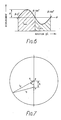
- the two averaged traces are shown as polar plots. Examples of such polar plots for wheels 12 and 10 are shown respectively in Figures 4 and 5.
- the centre of the axis is shown as point O
- the centre of the wheel is shown as point E
- the surface profile is shown by curve P.
- the distance between points O and E is the eccentricity of the wheel.
- the eccentricity and surface profile are shown on a greatly enlarged scale but nearly the whole of the radius of the wheel is omitted.
- the profile curve P is contracted towards point E.
- the irregularities in the surface profile may be seen in each of these figures.
- surface damage is indicated by arrow 76.
- the computer 68 subtracts the trace of the profile of wheel 12 from the output of transducer 40. This subtraction is performed in real time and reference signals from pick-up 46 are used to ensure that the subtraction is performed in phase with the actual position of wheel 12. As a result of the subtration, there is produced a partially corrected output signal.
- the trace of the profile of wheel 10 is hen subtrated from the partially corrected output signal. This subtraction is performed in phase with the actual position of wheel 10 using reference signals from pick-up 48. As a result of this subtraction, there is produced a fully corrected output signal.
- FIG 8 there is shown the output signal of transducer 40 in its uncorreted form.
- the output signal In the left hand half of Figure 4 there is shown the output signal with both wheels 10,12 rotating but before the first container reaches the nip between the two wheels.
- the output signal In the right hand half of Figure 4, there is shown the output signal as a series of containers pass between the wheels. The substantial displacement which occurs as the first container body enters the nip between the two wheels is shown by the vertical line 80. The length of a single container body is indicated by arrow L.
- there is considerable random variation in the output signal and, as has been explained, this is due largely to irregularities in the profiles of the two wheels 10,12 and their eccentricities.
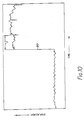
- FIG. 9 there is shown a graph of the output signal after it has been partially corrected by subtracting the profile of wheel 12.
- the left hand side shows the output signal before the first container body reaches the wheels 10,12
- the right hand half shows the output signal as a series of container bodies pass betwen the wheels
- the transition between the two is indicated by reference numral 80.
- the random variations in the output signal are much less than in Figure 8.
- the partially corrected output signal as illustrated in Figure 9 may provide a satisfactory indiation of weld thickness and thereby avoid the need of performing the second subtraction.
- FIG 10 there is shown a graph of the output signal after it has been fully corrected by substracting the profile of wheel 10. As may be seen particularly in the left hand side of Figure 10, the residual random variations in the fully corrected output signal are minimal. The variations which can be seen in the right hand half of Figure 10 largely represent actual variations in weld thickness.
- the results obtained may be displayed graphically, thus providing the operator of the welding apparatus with information on the welds being produced. Values for the average weld thickness along the whole can length or the thickness at a particular position may be also displayed. If the thickness falls outside acceptable limits, a warning may be given or operation of the welding apparatus may be stopped automatically. Since data is produced for each individual can body, this method may be used to detect welding faults in individual can bodies.
- Figure 11 is a graph of weld thickness plotted against the amount of overlap between the margins in each container body prior to welding. This overlap, in turn, is controlled by settings in the welding apparatus. The data for graph 11 were obtained by using a variety of machine settings. An overlap in the range 0.4 to 0.6 mm is regarded as acceptable. As may be seen, the thickness correlates closely with the overlap. Consequently, if the average thickness of the welds in container bodies departs from a desired value, this may be readily corrected by changing the setting so as to vary the overlap in the required direction.
- each container body passes through the nip between the electrode wheels 10,12, the whole of the outer surface is engaged by a set of support wheels.
- These support wheels are mounted on a carrier, the longitudinal position of which may be varied to obtain a correct setting. If its position departs from the correct setting, then errors occur in the welds.
- FIG 12 there is shown a series of traces 91 to 94 obtained by the second method. Between each pair of traces, the carrier holding the support wheels was moved a short distance downstream. In Figure 12, the length of a single can is indicated by arrow L. In trace 91, the weld exhibits a slight, but acceptable, thickening at the beginning and end of the container body. This thickening is caused by the carrier being located slightly too far upstream. The variations in thickness indicated by traces 92 and 93 are satisfactory and these traces represent optimum positions for the carrier. In trace 94, the weld has insufficient thickness at the beginning and end of the container body and this is caused by locating the carrier too far downstream. Thus, the present invention can be used to set the carrier to an optimum position.
Landscapes
- Engineering & Computer Science (AREA)
- Mechanical Engineering (AREA)
- Length Measuring Devices With Unspecified Measuring Means (AREA)
- Lining Or Joining Of Plastics Or The Like (AREA)
- Apparatuses And Processes For Manufacturing Resistors (AREA)
- Electrical Discharge Machining, Electrochemical Machining, And Combined Machining (AREA)
- Details Of Resistors (AREA)
- Extrusion Moulding Of Plastics Or The Like (AREA)
- Butt Welding And Welding Of Specific Article (AREA)
- Measurement Of Length, Angles, Or The Like Using Electric Or Magnetic Means (AREA)
Claims (7)
- Appareil de soudage électrique par résistance comprenant une première (12) et une deuxième (10) molettes formant électrodes de soudage agencées de manière à coopérer pour former des soudures dans une série de pièces à traiter (24, 28), la première (12) et la deuxième (10) molettes de soudage étant montées en vue d'un déplacement relatif l'une par rapport à l'autre, un moyen capteur (40) servant à capter le déplacement relatif entre la première (12) et la deuxième (10) molettes de soudage, ledit moyen capteur (40) étant agencé de manière à produire un signal de sortie, et un moyen de traitement (68) du signal de sortie du moyen capteur (40), caractérisé en ce que l'appareil inclut un moyen détecteur (46) servant à détecter la position de rotation de l'une (12) desdites molettes de soudage, ledit moyen capteur (40) étant agencé pour capter le déplacement relatif entre la première (12) et la deuxième (10) molettes de soudage, le signal de sortie du moyen capteur (40) représentant le déplacement relatif entre la première (12) et la deuxième (10) molettes de soudage en fonction du temps au fur et à mesure que les molettes de soudage (12, 10) tournent, et en ce que le moyen de traitement (68) inclut un tracé de profil, qui y est mémorisé, représentatif du profil de surface de ladite première molette de soudage (12), et le moyen de traitement (68) est agencé pour soustraire du signal de sortie du moyen capteur (40) de déplacement ledit tracé de profil en phase avec la position de rotation de ladite première molette de soudage (12), afin de produire un signal de sortie partiellement corrigé qui représente le déplacement relatif entre les molettes de soudage (12,10) en fonction de la rotation des molettes (12,10).
- Appareil de soudage électrique par résistance selon la revendication 1, caractérisé en ce que l'appareil inclut un deuxième moyen détecteur (48) servant à détecter la position de rotation de la deuxième molette de soudage (10), en ce que le moyen de traitement (68) est sensible à la sortie du deuxième moyen détecteur (48), et ce moyen de traitement (68) comprend un deuxième tracé de profil, qui y est mémorisé, représentatif du profil de surface de la deuxième molette de soudage (10), et en ce que ledit moyen de traitement (68) est agencé de manière à soustraire du signal de sortie partiellement corrigé le deuxième tracé de profil, afin de produire un signal de sortie complètement corrigé qui représente le déplacement relatif entre les molettes de soudage (12, 10), en fonction de la rotation des molettes (12,10).
- Appareil de soudage électrique par résistance selon la revendication 2, caractérisé en ce que le moyen de traitement (68) est agencé de manière à produire une série de tracés individuels qui représentent chacun la variation de déplacement entre la première et la deuxième molettes de soudage (10, 12) pendant une rotation unique d'une molette choisie parmi lesdites molettes de soudage, et ledit moyen de traitement (68) est agencé de manière à calculer une moyenne de plusieurs tracés individuels afin de produire un tracé moyen, représentatif du profil de surface de ladite molette de soudage choisie.
- Appareil de soudage électrique par résistance selon l'une quelconque des revendications précédentes, caractérisé en ce que l'une (10) des molettes de soudage est montée à rotation autour d'un axe fixe (14), tandis que l'autre (12) des molettes de soudage est montée à rotation autour d'un axe mobile (16), et le moyen capteur (40) est agencé de manière à capter le déplacement de ce deuxième axe (16).
- Procédé de surveillance d'un appareil de soudage électrique par résistance pourvu d'une première (12) et d'une deuxième (10) molettes formant électrodes de soudage montées en vue d'un déplacement relatif l'une par rapport à l'autre et agencées pour former des soudures dans des pièces à traiter (24, 28), consistant à capter un déplacement relatif entre la première (12) et la deuxième (10) molettes de soudage afin de produire un signal de sortie, et à traiter le signal de sortie, caractérisé en ce que le déplacement relatif entre la première (12) et la deuxième (10) molettes de soudage est capté afin de produire ledit signal de sortie, ledit signal de sortie représentant le déplacement relatif entre la première (12) et la deuxième (10) molettes de soudage en fonction du temps au fur et à mesure que les molettes de soudage (12, 10) tournent, et le procédé inclut les étapes additionnelles consistant à détecter la position de rotation de l'une (12) desdites molettes de soudage (12, 10), à mémoriser un tracé de profil représentatif du profil de surface de ladite première molette de soudage (12), et à soustraire du signal de sortie ledit tracé de profil en phase avec la position de rotation de ladite première molette de soudage (12), afin de produire un signal de sortie partiellement corrigé qui représente le déplacement relatif entre les molettes de soudage (12, 10) en fonction de la rotation des molettes (12, 10).
- Procédé de surveillance d'un appareil de soudage électrique par résistance selon la revendication 5, caractérisé par les étapes additionnelles consistant à détecter la position de rotation de la deuxième molette de soudage (10), mémoriser un tracé de profil représentatif du profil de surface de la deuxième molette de soudage (10), et soustraire du signal de sortie partiellement corrigé, le deuxième tracé de profil, afin de produire un signal complètement corrigé qui représente le déplacement relatif entre les molettes de soudage (12, 10) en fonction de la rotation des molettes de soudage (12, 10).
- Procédé selon la revendication 5 ou la revendication 6, caractérisé par les étapes additionnelles consistant à diviser le signal de sortie en une série de tracés qui représentent chacun la variation de déplacement entre la première (12) et la deuxième (10) molettes de soudage pendant une rotation unique de l'une desdites molettes (12, 10) choisie parmi les molettes de soudage, et à calculer une moyenne d'une série de tracés individuels afin de produire un tracé moyen, représentatif du profil de surface de ladite molette de soudage choisie.
Applications Claiming Priority (2)
| Application Number | Priority Date | Filing Date | Title |
|---|---|---|---|
| GB898902247A GB8902247D0 (en) | 1989-02-02 | 1989-02-02 | Resistance welding apparatus |
| GB8902247 | 1989-02-02 |
Related Parent Applications (1)
| Application Number | Title | Priority Date | Filing Date |
|---|---|---|---|
| EP90300134.5 Division | 1990-01-05 |
Publications (2)
| Publication Number | Publication Date |
|---|---|
| EP0438204A1 EP0438204A1 (fr) | 1991-07-24 |
| EP0438204B1 true EP0438204B1 (fr) | 1993-10-20 |
Family
ID=10650981
Family Applications (2)
| Application Number | Title | Priority Date | Filing Date |
|---|---|---|---|
| EP91200567A Expired - Lifetime EP0438204B1 (fr) | 1989-02-02 | 1990-01-05 | Appareil de soudage par résistance |
| EP90300134A Expired - Lifetime EP0381312B1 (fr) | 1989-02-02 | 1990-01-05 | Appareil de soudage par résistance |
Family Applications After (1)
| Application Number | Title | Priority Date | Filing Date |
|---|---|---|---|
| EP90300134A Expired - Lifetime EP0381312B1 (fr) | 1989-02-02 | 1990-01-05 | Appareil de soudage par résistance |
Country Status (8)
| Country | Link |
|---|---|
| US (1) | US5021626A (fr) |
| EP (2) | EP0438204B1 (fr) |
| AT (2) | ATE103517T1 (fr) |
| DE (2) | DE69004068T2 (fr) |
| DK (2) | DK0381312T3 (fr) |
| ES (2) | ES2050943T3 (fr) |
| GB (2) | GB8902247D0 (fr) |
| ZA (1) | ZA90409B (fr) |
Families Citing this family (12)
| Publication number | Priority date | Publication date | Assignee | Title |
|---|---|---|---|---|
| CH684467A5 (de) * | 1991-12-16 | 1994-09-30 | Elpatronic Ag | Verfahren zur Ueberwachung der Schweissqualität beim Quetschnahtschweissen. |
| EP0714723B1 (fr) * | 1994-11-28 | 1999-08-11 | Elpatronic Ag | Procédé de soudage par molettes, ainsi que le maintien de la tête ayant les dites molettes à une machine de soudage par résistance |
| WO1997043075A1 (fr) | 1996-05-14 | 1997-11-20 | Newcor, Inc. | Agencement de palier a faible inertie pour molette de machine de soudage continu |
| GB9626065D0 (en) * | 1996-12-16 | 1997-02-05 | Metal Box Plc | Measurement of welds |
| DE19917439C2 (de) * | 1999-04-17 | 2002-08-08 | Bosch Gmbh Robert | Integriert-optischer Sensor |
| US8803023B2 (en) * | 2007-11-29 | 2014-08-12 | Isg Technologies | Seam welding |
| JP5457090B2 (ja) * | 2009-06-30 | 2014-04-02 | 本田技研工業株式会社 | 排気管製造方法及び排気管製造装置 |
| NL2003351C2 (en) * | 2009-08-13 | 2011-02-15 | Univ Delft Tech | Method and instumentation for detection of rail top defects. |
| CN103240520B (zh) * | 2013-04-29 | 2015-05-13 | 翟佑华 | 自动查找卷钉机焊钉时机的方法及装置 |
| JP6258799B2 (ja) * | 2014-07-04 | 2018-01-10 | 本田技研工業株式会社 | シーム溶接装置及びシーム溶接方法 |
| GB201815121D0 (en) * | 2018-09-17 | 2018-10-31 | Crown Packaging Technology Inc | Welding of can bodies |
| JP7119025B2 (ja) * | 2020-06-03 | 2022-08-16 | 株式会社東芝 | 制御装置、制御システム、溶接システム、制御方法、接合体の製造方法、プログラム、及び記憶媒体 |
Family Cites Families (6)
| Publication number | Priority date | Publication date | Assignee | Title |
|---|---|---|---|---|
| US2818491A (en) * | 1955-07-13 | 1957-12-31 | Elox Corp Michigan | Electrode wear compensation |
| GB1177923A (en) * | 1966-02-21 | 1970-01-14 | Davy & United Eng Co Ltd | Rolling Mills |
| US4376883A (en) * | 1980-07-30 | 1983-03-15 | American Can Company | Monitoring weld quality via forging assembly dynamics |
| GB8613130D0 (en) * | 1986-05-30 | 1986-07-02 | Metal Box Plc | Resistance welding of can bodies |
| DE3711771A1 (de) * | 1987-04-08 | 1988-10-27 | Sts Systemtechnik Und Software | Verfahren und einrichtung fuer die prozessreglung beim punktschweissen |
| CH677891A5 (fr) * | 1988-12-16 | 1991-07-15 | Elpatronic Ag |
-
1989
- 1989-02-02 GB GB898902247A patent/GB8902247D0/en active Pending
-
1990
- 1990-01-05 DK DK90300134.5T patent/DK0381312T3/da active
- 1990-01-05 DE DE91200567T patent/DE69004068T2/de not_active Expired - Lifetime
- 1990-01-05 ES ES90300134T patent/ES2050943T3/es not_active Expired - Lifetime
- 1990-01-05 GB GB9000231A patent/GB2227963B/en not_active Expired - Lifetime
- 1990-01-05 DE DE69007646T patent/DE69007646T2/de not_active Expired - Lifetime
- 1990-01-05 EP EP91200567A patent/EP0438204B1/fr not_active Expired - Lifetime
- 1990-01-05 AT AT90300134T patent/ATE103517T1/de not_active IP Right Cessation
- 1990-01-05 ES ES199091200567T patent/ES2046842T3/es not_active Expired - Lifetime
- 1990-01-05 EP EP90300134A patent/EP0381312B1/fr not_active Expired - Lifetime
- 1990-01-16 US US07/466,463 patent/US5021626A/en not_active Expired - Lifetime
- 1990-01-19 ZA ZA90409A patent/ZA90409B/xx unknown
-
1991
- 1991-03-15 DK DK91200567.5T patent/DK0438204T3/da active
- 1991-03-15 AT AT91200567T patent/ATE96068T1/de not_active IP Right Cessation
Also Published As
| Publication number | Publication date |
|---|---|
| DE69007646D1 (de) | 1994-05-05 |
| EP0438204A1 (fr) | 1991-07-24 |
| DE69004068D1 (de) | 1993-11-25 |
| ZA90409B (en) | 1990-10-31 |
| DE69004068T2 (de) | 1994-03-03 |
| DE69007646T2 (de) | 1994-07-14 |
| EP0381312A1 (fr) | 1990-08-08 |
| GB2227963B (en) | 1993-02-03 |
| ES2046842T3 (es) | 1994-02-01 |
| GB9000231D0 (en) | 1990-03-07 |
| ES2050943T3 (es) | 1994-06-01 |
| EP0381312B1 (fr) | 1994-03-30 |
| US5021626A (en) | 1991-06-04 |
| DK0381312T3 (da) | 1994-07-18 |
| GB8902247D0 (en) | 1989-03-22 |
| GB2227963A (en) | 1990-08-15 |
| DK0438204T3 (da) | 1994-02-21 |
| ATE103517T1 (de) | 1994-04-15 |
| ATE96068T1 (de) | 1993-11-15 |
Similar Documents
| Publication | Publication Date | Title |
|---|---|---|
| EP0438204B1 (fr) | Appareil de soudage par résistance | |
| US4028522A (en) | Multi-mode structural weld monitor on a time base | |
| US5778549A (en) | Correcting measurement errors | |
| US4144766A (en) | Apparatus for the in-situ detection and location of flaws in welds | |
| Gedeon et al. | Measurement of dynamic electrical and mechanical properties of resistance spot welds | |
| CA2004311C (fr) | Montage permettant de surveiller la qualite des soudures electriques | |
| US5291423A (en) | Arrangement for monitoring the quality of electric welds | |
| US4734640A (en) | Welding current measuring apparatus | |
| JPH0316233B2 (fr) | ||
| JPH0466364A (ja) | 配管内走行ロボット | |
| JPH04279826A (ja) | 可変速回転系異常診断方法及びその装置 | |
| JP5030412B2 (ja) | 缶胴溶接部の溶接良否判別方法および装置 | |
| JPH11285824A (ja) | ステンレス薄板すみ肉tig溶接の溶接欠陥検知方法及び溶接診断機能付自動溶接装置 | |
| US4788405A (en) | Weld thickness monitoring in resistance welding apparatus | |
| US6184491B1 (en) | Method and apparatus for monitoring weld quality | |
| JP3620218B2 (ja) | 歯車検査装置及び方法 | |
| CN117029680A (zh) | 焊缝检测方法及焊接系统 | |
| JPH0625707B2 (ja) | 歯車の歯振れ測定装置 | |
| JP2010019738A (ja) | 缶胴溶接部の検査方法 | |
| JP4276714B2 (ja) | 測定装置 | |
| JPS6315538B2 (fr) | ||
| GB2160979A (en) | Automatic machine for checking the rims of disc wheels for motor vehicles | |
| JPH01181975A (ja) | 溶接ロボットの制御装置 | |
| JPH03226384A (ja) | 抵抗溶接機の溶接監視装置 | |
| JPS59229233A (ja) | 歪取り方法 |
Legal Events
| Date | Code | Title | Description |
|---|---|---|---|
| PUAI | Public reference made under article 153(3) epc to a published international application that has entered the european phase |
Free format text: ORIGINAL CODE: 0009012 |
|
| 17P | Request for examination filed |
Effective date: 19910315 |
|
| AC | Divisional application: reference to earlier application |
Ref document number: 381312 Country of ref document: EP |
|
| AK | Designated contracting states |
Kind code of ref document: A1 Designated state(s): AT BE CH DE DK ES FR GB GR IT LI LU NL SE |
|
| 17Q | First examination report despatched |
Effective date: 19920828 |
|
| RAP1 | Party data changed (applicant data changed or rights of an application transferred) |
Owner name: CARNAUDMETALBOX PLC |
|
| GRAA | (expected) grant |
Free format text: ORIGINAL CODE: 0009210 |
|
| AC | Divisional application: reference to earlier application |
Ref document number: 381312 Country of ref document: EP |
|
| AK | Designated contracting states |
Kind code of ref document: B1 Designated state(s): AT BE CH DE DK ES FR GB GR IT LI LU NL SE |
|
| REF | Corresponds to: |
Ref document number: 96068 Country of ref document: AT Date of ref document: 19931115 Kind code of ref document: T |
|
| REF | Corresponds to: |
Ref document number: 69004068 Country of ref document: DE Date of ref document: 19931125 |
|
| ITF | It: translation for a ep patent filed | ||
| EPTA | Lu: last paid annual fee | ||
| ET | Fr: translation filed | ||
| REG | Reference to a national code |
Ref country code: ES Ref legal event code: FG2A Ref document number: 2046842 Country of ref document: ES Kind code of ref document: T3 |
|
| REG | Reference to a national code |
Ref country code: DK Ref legal event code: T3 |
|
| REG | Reference to a national code |
Ref country code: GR Ref legal event code: FG4A Free format text: 3010411 |
|
| PLBE | No opposition filed within time limit |
Free format text: ORIGINAL CODE: 0009261 |
|
| STAA | Information on the status of an ep patent application or granted ep patent |
Free format text: STATUS: NO OPPOSITION FILED WITHIN TIME LIMIT |
|
| 26N | No opposition filed | ||
| EAL | Se: european patent in force in sweden |
Ref document number: 91200567.5 |
|
| PGFP | Annual fee paid to national office [announced via postgrant information from national office to epo] |
Ref country code: LU Payment date: 19990104 Year of fee payment: 10 |
|
| PG25 | Lapsed in a contracting state [announced via postgrant information from national office to epo] |
Ref country code: LU Free format text: LAPSE BECAUSE OF NON-PAYMENT OF DUE FEES Effective date: 20000105 |
|
| REG | Reference to a national code |
Ref country code: GB Ref legal event code: IF02 |
|
| PG25 | Lapsed in a contracting state [announced via postgrant information from national office to epo] |
Ref country code: IT Free format text: LAPSE BECAUSE OF NON-PAYMENT OF DUE FEES Effective date: 20050105 |
|
| PGFP | Annual fee paid to national office [announced via postgrant information from national office to epo] |
Ref country code: DK Payment date: 20090113 Year of fee payment: 20 Ref country code: ES Payment date: 20090122 Year of fee payment: 20 Ref country code: AT Payment date: 20090115 Year of fee payment: 20 |
|
| PGFP | Annual fee paid to national office [announced via postgrant information from national office to epo] |
Ref country code: DE Payment date: 20090122 Year of fee payment: 20 Ref country code: NL Payment date: 20090114 Year of fee payment: 20 |
|
| PGFP | Annual fee paid to national office [announced via postgrant information from national office to epo] |
Ref country code: GB Payment date: 20090122 Year of fee payment: 20 Ref country code: GR Payment date: 20090123 Year of fee payment: 20 Ref country code: CH Payment date: 20090115 Year of fee payment: 20 |
|
| PGFP | Annual fee paid to national office [announced via postgrant information from national office to epo] |
Ref country code: BE Payment date: 20090219 Year of fee payment: 20 |
|
| PGFP | Annual fee paid to national office [announced via postgrant information from national office to epo] |
Ref country code: SE Payment date: 20090114 Year of fee payment: 20 |
|
| PGFP | Annual fee paid to national office [announced via postgrant information from national office to epo] |
Ref country code: FR Payment date: 20090115 Year of fee payment: 20 |
|
| REG | Reference to a national code |
Ref country code: CH Ref legal event code: PL |
|
| REG | Reference to a national code |
Ref country code: DK Ref legal event code: EUP |
|
| REG | Reference to a national code |
Ref country code: GB Ref legal event code: PE20 Expiry date: 20100104 |
|
| BE20 | Be: patent expired |
Owner name: *CARNAUDMETALBOX P.L.C. Effective date: 20100105 |
|
| NLV7 | Nl: ceased due to reaching the maximum lifetime of a patent |
Effective date: 20100105 |
|
| EUG | Se: european patent has lapsed | ||
| REG | Reference to a national code |
Ref country code: ES Ref legal event code: FD2A Effective date: 20100107 |
|
| PG25 | Lapsed in a contracting state [announced via postgrant information from national office to epo] |
Ref country code: GB Free format text: LAPSE BECAUSE OF EXPIRATION OF PROTECTION Effective date: 20100104 Ref country code: ES Free format text: LAPSE BECAUSE OF EXPIRATION OF PROTECTION Effective date: 20100107 |
|
| PGFP | Annual fee paid to national office [announced via postgrant information from national office to epo] |
Ref country code: IT Payment date: 20090127 Year of fee payment: 20 |
|
| PGRI | Patent reinstated in contracting state [announced from national office to epo] |
Ref country code: IT Effective date: 20091201 |
|
| PG25 | Lapsed in a contracting state [announced via postgrant information from national office to epo] |
Ref country code: NL Free format text: LAPSE BECAUSE OF EXPIRATION OF PROTECTION Effective date: 20100105 |
|
| PG25 | Lapsed in a contracting state [announced via postgrant information from national office to epo] |
Ref country code: DE Free format text: LAPSE BECAUSE OF EXPIRATION OF PROTECTION Effective date: 20100105 |