EP0438325A1 - Fire wall for the body of a motor vehicle - Google Patents
Fire wall for the body of a motor vehicle Download PDFInfo
- Publication number
- EP0438325A1 EP0438325A1 EP91400002A EP91400002A EP0438325A1 EP 0438325 A1 EP0438325 A1 EP 0438325A1 EP 91400002 A EP91400002 A EP 91400002A EP 91400002 A EP91400002 A EP 91400002A EP 0438325 A1 EP0438325 A1 EP 0438325A1
- Authority
- EP
- European Patent Office
- Prior art keywords
- partition according
- marginal
- practically
- sides
- shaped
- Prior art date
- Legal status (The legal status is an assumption and is not a legal conclusion. Google has not performed a legal analysis and makes no representation as to the accuracy of the status listed.)
- Granted
Links
- 238000005192 partition Methods 0.000 claims description 33
- 230000002093 peripheral effect Effects 0.000 claims description 4
- 239000011248 coating agent Substances 0.000 claims description 2
- 238000000576 coating method Methods 0.000 claims description 2
- 239000006260 foam Substances 0.000 claims description 2
- 238000005304 joining Methods 0.000 claims description 2
- 238000010276 construction Methods 0.000 abstract description 2
- 239000000243 solution Substances 0.000 description 6
- 238000000034 method Methods 0.000 description 5
- 238000004378 air conditioning Methods 0.000 description 4
- 239000000463 material Substances 0.000 description 3
- 239000003677 Sheet moulding compound Substances 0.000 description 2
- 238000000429 assembly Methods 0.000 description 2
- 230000004888 barrier function Effects 0.000 description 2
- KXGFMDJXCMQABM-UHFFFAOYSA-N 2-methoxy-6-methylphenol Chemical compound [CH]OC1=CC=CC([CH])=C1O KXGFMDJXCMQABM-UHFFFAOYSA-N 0.000 description 1
- 230000000712 assembly Effects 0.000 description 1
- 230000006835 compression Effects 0.000 description 1
- 238000007906 compression Methods 0.000 description 1
- 238000001816 cooling Methods 0.000 description 1
- 238000009826 distribution Methods 0.000 description 1
- 239000000835 fiber Substances 0.000 description 1
- 239000000945 filler Substances 0.000 description 1
- 230000006870 function Effects 0.000 description 1
- 210000002816 gill Anatomy 0.000 description 1
- 238000001746 injection moulding Methods 0.000 description 1
- 238000004519 manufacturing process Methods 0.000 description 1
- 230000005226 mechanical processes and functions Effects 0.000 description 1
- 239000005011 phenolic resin Substances 0.000 description 1
- 229920001568 phenolic resin Polymers 0.000 description 1
- 229920001225 polyester resin Polymers 0.000 description 1
- 239000004645 polyester resin Substances 0.000 description 1
- 230000002787 reinforcement Effects 0.000 description 1
- 239000000725 suspension Substances 0.000 description 1
- 229920002994 synthetic fiber Polymers 0.000 description 1
- 229920001169 thermoplastic Polymers 0.000 description 1
- 239000004416 thermosoftening plastic Substances 0.000 description 1
Images

Classifications
-
- B—PERFORMING OPERATIONS; TRANSPORTING
- B62—LAND VEHICLES FOR TRAVELLING OTHERWISE THAN ON RAILS
- B62D—MOTOR VEHICLES; TRAILERS
- B62D25/00—Superstructure or monocoque structure sub-units; Parts or details thereof not otherwise provided for
- B62D25/08—Front or rear portions
- B62D25/14—Dashboards as superstructure sub-units
Definitions
- the present invention relates to motor vehicles and relates, more particularly, to a separating partition intended to be placed between a front compartment, preferably an engine compartment, and a passenger compartment of a structure or shell of a motor vehicle.
- This type of design allows a high degree of automation and allows the implementation of robots and programmable controllers. In addition to this advantage, this type of solution makes it possible to adapt a vehicle very quickly to changes in fashion aesthetics and user expectations.
- the front compartment, very often engine, of a vehicle structure is separated from the passenger compartment by a partition or apron.
- the previous entity which includes for example the powerplant and the wheel set with its suspension, is often also provided with a cross member which makes it possible to close the window of the windshield at the bottom of this one.
- the separating partition also receives, usually, directly or indirectly, in particular a steering column, which means that this partition must be able to withstand and transmit significant forces.
- the object of the invention is to remedy most of the drawbacks of known solutions by giving such a partition a configuration which enables it to withstand and / or transmit forces which were previously transmitted essentially, in particular by the lower cross member of the bay. windshield.
- the subject of the invention is an improved separating partition for a motor vehicle structure which is intended to be placed between a front engine compartment and a passenger compartment.
- This separating partition is characterized in that it comprises a practically rectangular panel whose four sides are provided with a peripheral rim and delimit a central bowl with a bottom and which is shaped to obtain at least two longitudinal beams which are practically parallel to the long sides, which are approximately U-shaped and open opposite this bottom, which are practically continuous from one of the short sides to the other, and which are one margin located near one of these long sides and the other median located near the middle of the bowl.
- the marginal beam is intended to constitute a box for an air conditioning system and the middle beam is intended to constitute a housing for a direction.
- a dividing wall perfected according to the invention is intended to equip a structure 10 of a motor vehicle to separate a front compartment, for example engine M from a living space H.
- this structure 10 only partially shown and schematically comprises an awning 11, a lower crossmember 12, a front spar 13, lateral uprights 14 and carries connectors not shown, for example flexible connectors, a steering column and pedal support 16 with a set of pedal pedals 17 and a steering column 18. All of this is conventional and , for example, disclosed in the aforementioned patent applications.
- a separating partition according to the invention comprises a panel 20, practically rectangular, the four sides of which, the large 201 and the small 202, are provided with a peripheral flange 203. These sides delimit a central bowl 204 with a bottom 205.
- this panel is shaped to obtain at least two beams, a marginal beam 21 and a median beam 22, both longitudinal and practically parallel to the long sides 201. It can be seen that these two beams 21 and 22 have a approximately U-shaped cross section and are open opposite this bottom 205. As can be seen, the two beams 21, 22 are practically continuous from one of the short sides 202 to the other. As can be seen, the marginal beam 21 is located near one of the long sides 201 while the middle beam 22 is located near the middle of the bowl 204.
- the marginal beam 21 comprises two wings 212 vis-à-vis practically parallel to the long sides 201, and a bridge 213 connecting the wings 212. From preferably, at least one hearing 211 locally pierces the beam 21, preferably the bridge 213. As can be observed, on either side of the marginal beam 21, outside the wings 212, the bottom 205 of the central bowl forms bases 110. These bases are more particularly intended to receive the canopy 11. In this way, it is understood that this beam, initially open, can then be closed and thus forms a box 210, very especially suitable for serving as a conduit. air for an air conditioning system not shown.
- the arrangement of the gills 211, their orientation and their distribution, possibly supplemented by illustrated side vents, makes it possible to distribute an air curtain towards the windshield or flows in the passenger compartment; this is well known and that is why we will not extend it further.
- the central beam 22 comprises two opposite wings 222, practically parallel to the long sides 201 and a bridge 223 connecting the wings 222. As can be observed, this central beam is pierced with a orifice 221 intended to be crossed by a shaft 181 of a steering column 18.
- the separating partition according to the invention comprises a panel 20 which is also shaped to obtain an intermediate beam 23 which is also practically parallel to the long sides 201.
- this intermediate beam 23 is located between the beams marginal 21 and median 22. It can also be noted that this beam is discontinuous, interrupted between the two short sides 202 by a depression 231.
- the intermediate beam 23 has an approximately U-shaped configuration and is open opposite the bottom 205. As we can observe it, the height above the bottom 205 of this intermediate beam 23 is greater than that of the marginal 21 and median beams 22.
- this intermediate beam is shaped to form an enclosure 230 intended to receive accessories.
- this intermediate beam 23 in the configuration of a flared U is delimited by two opposite sides 232 and by a facade 233 joining them. It can be noted that the depression 231 is delimited by cheeks 2310 opposite practically perpendicular to these flank 232 and facade 233. It will also be observed that this intermediate beam 23 is crossed by openings 2311 and clearances 2312 situated, preferably, on the facade 233.
- the bottom 205 is pierced with cutouts 206 for crossing the connectors and passages 207 for the pedals of a crankset 17.
- the pedals of the crankset 17 are carried by a support steering column-pedal 16 which is housed in depression 231.
- This bottom also forms supports 280 for receiving a brake assist system and a rack mounting of the steering column.
- the bottom 205 comprises, between the central beam 22 and the long side 201 opposite to that close to the marginal beam 21, supports 121 and seats 122 for receiving, respectively, the lower cross member 12 and spar before 13 of the framework 10 which was discussed previously.
- peripheral rim 203 carries, on its short sides 202, supports 114 intended to receive the lateral uprights 14 of the structure.
- the partition according to the invention serves as a service, a servant workshop for assembly since it can receive, on one side, a steering rack support and a brake assist system and, on the other side, a dashboard and a column support steering-crankset.
- Such a separating partition according to the invention can be manufactured with synthetic materials to which fillers and / or reinforcements are added in the form of suitable fibers, in order to give it the desired properties, in particular mechanical.
- synthetic materials to which fillers and / or reinforcements are added in the form of suitable fibers, in order to give it the desired properties, in particular mechanical.
- SMC Sheet Molding Compound
- TRE Reinforced Thermoplastic Estempable
- this partition according to the invention is provided with a coating 19 based on foam 191 carrying on its outer face a septum or film 192 to give it an attractive look and feel, like it is classic.
- this improved partition according to the invention also serves as a thermal barrier and also plays the role of fire barrier according to the standards applicable in the matter.
Landscapes
- Engineering & Computer Science (AREA)
- Chemical & Material Sciences (AREA)
- Combustion & Propulsion (AREA)
- Transportation (AREA)
- Mechanical Engineering (AREA)
- Body Structure For Vehicles (AREA)
- Vehicle Step Arrangements And Article Storage (AREA)
Abstract
Description
La présente invention concerne les véhicules automobiles et est relative, plus particulièrement, à une cloison séparatrice destinée à être placée entre un compartiment antérieur, de préférence moteur, et un habitacle d'une structure ou coque de véhicule automobile.The present invention relates to motor vehicles and relates, more particularly, to a separating partition intended to be placed between a front compartment, preferably an engine compartment, and a passenger compartment of a structure or shell of a motor vehicle.
La tendance contemporaine des techniques de fabrication des véhicules automobiles est de concevoir leur structure ou coque sous forme modulaire. Outre ce fait, ces structures modulaires sont préalablement équipées d'entités montées et assemblées, voire contrôlées, hors des lignes proprement dites d'assemblage. Ces entités prééquipées se composent souvent elles-mêmes d'ensembles et de sous-ensembles qui ont été préalablement construits et contrôlés avant d'être réunis pour constituer ces entités.The contemporary trend in motor vehicle manufacturing techniques is to design their structure or shell in modular form. In addition to this fact, these modular structures are previously equipped with assembled and assembled, or even controlled, entities outside of the actual assembly lines. These pre-equipped entities often themselves consist of assemblies and sub-assemblies which have been previously constructed and checked before being brought together to constitute these entities.
Ce type de conception permet un haut degré d'automatisation et autorise la mise en oeuvre de robots et d'automates programmables. Outre cet avantage, ce type de solution permet d'adapter très rapidement un véhicule aux changements d'esthétiques de la mode et aux attentes des utilisateurs.This type of design allows a high degree of automation and allows the implementation of robots and programmable controllers. In addition to this advantage, this type of solution makes it possible to adapt a vehicle very quickly to changes in fashion aesthetics and user expectations.
Ce type de solutions est, par exemple, illustré dans les demandes de brevets français 87-05 934, 87-06 734 et 88-10 627 de la Demanderesse.This type of solution is, for example, illustrated in French patent applications 87-05 934, 87-06 734 and 88-10 627 of the Applicant.
Quel que soit le type de solution pratiquement retenue, le compartiment antérieur, très souvent moteur, d'une structure de véhicule est séparé de l'habitacle par une cloison ou tablier. Dans le cas où le véhicule est construit sous forme modulaire, l'entité antérieure qui comprend par exemple le groupe mototracteur et le train de roues avec sa suspension, est souvent aussi munie d'une traverse qui permet de clore la baie du pare-brise à la partie inférieure de celle-ci.Whatever the type of solution practically adopted, the front compartment, very often engine, of a vehicle structure is separated from the passenger compartment by a partition or apron. In the case where the vehicle is built in modular form, the previous entity which includes for example the powerplant and the wheel set with its suspension, is often also provided with a cross member which makes it possible to close the window of the windshield at the bottom of this one.
La cloison séparatrice reçoit aussi, habituellement, directement ou indirectement, en particulier une colonne de direction ce qui fait que cette cloison doit pouvoir supporter et transmettre des efforts importants.The separating partition also receives, usually, directly or indirectly, in particular a steering column, which means that this partition must be able to withstand and transmit significant forces.
On comprend donc que pour ce type de solution modulaire, il est aussi primordial que cette cloison participe à la résistance mécanique de l'ossature, structure, coque ou caisse du véhicule.It is therefore understood that for this type of modular solution, it is also essential that this partition participates in the mechanical strength of the frame, structure, shell or body of the vehicle.
Il est classique d'équiper les véhicules d'un système de climatisation qui est habituellement réparti de part et d'autre de cette cloison entre le compartiment antérieur et l'habitacle.It is conventional to equip vehicles with an air conditioning system which is usually distributed on either side of this partition between the front compartment and the passenger compartment.
Le but de l'invention est de remédier à la plupart des inconvénients des solutions connues en donnant à une telle cloison une configuration qui lui permet de supporter et/ou de transmettre des efforts qui étaient précédemment transmis essentiellement notamment par la traverse inférieure de baie de pare-brise.The object of the invention is to remedy most of the drawbacks of known solutions by giving such a partition a configuration which enables it to withstand and / or transmit forces which were previously transmitted essentially, in particular by the lower cross member of the bay. windshield.
L'invention a pour objet une cloison séparatrice perfectionnée pour structure de véhicule automobile qui est destinée à être placée entre un compartiment antérieur moteur et un habitacle. Cette cloison séparatrice est caractérisée en ce qu'elle comprend un panneau pratiquement rectangulaire dont les quatre côtés sont munis d'un rebord périphérique et délimitent une cuvette centrale avec un fond et qui est conformé pour obtenir au moins deux poutres longitudinales qui sont pratiquement parallèles aux grands côtés, qui sont approximativement en U et ouvertes à l'opposé de ce fond, qui sont pratiquement continues d'un des petits côtés à l'autre, et qui sont l'une marginale située à proximité d'un de ces grands côtés et l'autre médiane située à proximité du milieu de la cuvette. De préférence, la poutre marginale est destinée à constituer un caisson pour un système de climatisation et la poutre médiane est destinée à constituer un logement pour une direction.The subject of the invention is an improved separating partition for a motor vehicle structure which is intended to be placed between a front engine compartment and a passenger compartment. This separating partition is characterized in that it comprises a practically rectangular panel whose four sides are provided with a peripheral rim and delimit a central bowl with a bottom and which is shaped to obtain at least two longitudinal beams which are practically parallel to the long sides, which are approximately U-shaped and open opposite this bottom, which are practically continuous from one of the short sides to the other, and which are one margin located near one of these long sides and the other median located near the middle of the bowl. Preferably, the marginal beam is intended to constitute a box for an air conditioning system and the middle beam is intended to constitute a housing for a direction.
D'autres caractéristiques de l'invention ressortiront de la lecture de la description et des revendications qui suivent et de l'examen du dessin annexé, donné seulement à titre d'exemple, où:
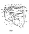
- la Figure 1 est une vue perspective schématique d'une des faces d'un mode de réalisation d'une cloison séparatrice selon l'invention;
- la Figure 2 est une vue perspective schématique de la face opposée de la cloison séparatrice de la Figure 1;
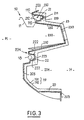
- la Figure 3 est une coupe transversale verticale de ce mode de réalisation des Figures 1 et 2 selon le plan 3-3 et;
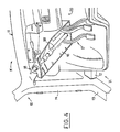
- la Figure 4 est une vue partielle, analogue à celle de la Figure 1, d'une cloison selon l'invention partiellement équipée et placée à proximité d'une structure seulement dessinée en partie.
- Figure 1 is a schematic perspective view of one of the faces of an embodiment of a separating partition according to the invention;
- Figure 2 is a schematic perspective view of the opposite face of the partition wall of Figure 1;
- Figure 3 is a vertical cross section of this embodiment of Figures 1 and 2 along the plane 3-3 and;
- Figure 4 is a partial view, similar to that of Figure 1, of a partition according to the invention partially equipped and placed near a structure only partially drawn.
Les techniques de construction en matière d'automobile étant bien connues, on ne décrira par la suite que ce qui se rapporte directement ou indirectement à l'invention. Pour le surplus, le spécialiste de la technique considérée puisera dans les solutions classiques courantes à sa disposition pour faire face aux problèmes particuliers auxquels il est confronté.Construction techniques in the automobile industry being well known, only that which relates directly or indirectly to the invention will be described below. For the rest, the specialist in the technique considered will draw on the current conventional solutions at his disposal to deal with the particular problems with which he is confronted.
Dans ce qui suit, un même numéro de référence identifie toujours un élément homologue quel que soit le mode de réalisation.In what follows, the same reference number always identifies a homologous element whatever the embodiment.
Une cloison séparatrice perfectionnée selon l'invention est destinée à équiper une structure 10 de véhicule automobile pour séparer un compartiment antérieur par exemple moteur M d'un habitable H. Comme il est classique, cette structure 10, seulement représentée partiellement et schématiquement comprend un auvent 11, une traverse inférieure 12, un longeron avant 13, des montants latéraux 14 et porte des connecteurs non illustrés par exemple flexibles, un support de colonne de direction et pédalier 16 avec un jeu de pédales de pédalier 17 et une colonne de direction 18. Tout ceci est classique et, par exemple, exposé dans les demandes de brevets précitées.A dividing wall perfected according to the invention is intended to equip a
Comme on le voit en observant les figures du dessin, une cloison séparatrice selon l'invention comprend un panneau 20, pratiquement rectangulaire dont les quatre côtés, les grands 201 et les petits 202, sont munis d'un rebord 203 périphérique. Ces côtés délimitent une cuvette 204 centrale avec un fond 205.As can be seen by observing the figures of the drawing, a separating partition according to the invention comprises a
Comme on peut l'observer, ce panneau est conformé pour obtenir au moins deux poutres, une poutre marginale 21 et une poutre médiane 22, toutes deux longitudinales et pratiquement parallèles aux grands côtés 201. On voit que ces deux poutres 21 et 22 ont une section droite approximativement en U et sont ouvertes à l'opposé de ce fond 205. Comme on peut le relever, les deux poutres 21, 22 sont pratiquement continues d'un des petits côtés 202 à l'autre. Comme on peut le voir, la poutre 21 marginale est située à proximité d'un des grands côtés 201 alors que la poutre médiane 22 est située à proximité du milieu de la cuvette 204.As can be observed, this panel is shaped to obtain at least two beams, a
La poutre marginale 21 comprend deux ailes 212 en vis-à-vis pratiquement parallèles aux grands côtés 201, et un pont 213 reliant les ailes 212. De préférence, au moins une ouie 211 transperce localement la poutre 21, de préférence le pont 213. Comme on peut l'observer, de part et d'autre de la poutre marginale 21, à l'extérieur des ailes 212, le fond 205 de la cuvette centrale forme des embases 110. Ces embases sont plus particulièrement destinées à recevoir l'auvent 11. De la sorte, on comprend que cette poutre initialement ouverte peut alors être close et forme ainsi un caisson 210, tout spécialement apte à servir de conduite d'air pour un système de climatisation non représenté. La disposition des ouies 211, leur orientation et leur répartition, éventuellement complétées par des évents latéraux illustrés, permet de distribuer un rideau d'air vers le pare-brise ou des flux dans l'habitacle; ceci est bien connu et c'est pourquoi on ne s'y étendra pas plus amplement.The
Comme on le voit, la poutre médiane 22 comprend deux ailes 222 en vis-à-vis, pratiquement parallèles aux grands côtés 201 et un pont 223 reliant les ailes 222. Comme on peut l'observer, cette poutre médiane est transpercée d'un orifice 221 destiné à être traversé par un arbre 181 d'une colonne de direction 18.As can be seen, the
La cloison séparatrice selon l'invention comprend un panneau 20 qui est aussi conformé pour obtenir une poutre 23 intermédiaire qui est, elle aussi, pratiquement parallèle aux grands côtés 201. Comme on peut l'observer, cette poutre intermédiaire 23 est située entre les poutres marginale 21 et médiane 22. On peut noter aussi que cette poutre est discontinue, interrompue entre les deux petits côtés 202 par une dépression 231. La poutre 23 intermédiaire à une configuration approximativement en U et est ouverte à l'opposé du fond 205. Comme on peut l'observer, la hauteur au-dessus du fond 205 de cette poutre intermédiaire 23 est supérieure à celle des poutres marginale 21 et médiane 22. De préférence, cette poutre intermédiaire est conformée pour constituer une enceinte 230 destinée à recevoir des accessoires. Comme on peut l'observer, cette poutre intermédiaire 23 en configuration de U évasé est délimitée par deux flancs 232 en regard et par une façade 233 les réunissant. On peut noter que la dépression 231 est délimitée par des joues 2310 opposées pratiquement perpendiculaires à ces flanc 232 et façade 233. On observera aussi que cette poutre intermédiaire 23 est traversée par des ouvertures 2311 et des dégagements 2312 situés, de préférence, sur la façade 233.The separating partition according to the invention comprises a
En examinant les figures du dessin, on voit aussi que le fond 205 est transpercé de découpes 206 pour la traversée des connecteurs et de passages 207 pour les pédales d'un pédalier 17. De préférence, les pédales du pédalier 17 sont portées par un support de colonne de direction-pédalier 16 qui est logé dans la dépression 231. Ce fond forme aussi des supports 280 pour recevoir un système d'assistance au freinage et une monture de la crémaillère de la colonne de direction.By examining the figures in the drawing, it can also be seen that the
Comme on peut l'observer, le fond 205 comprend, entre la poutre médiane 22 et le grand côté 201 opposé à celui proche de la poutre marginale 21, des appuis 121 et des assises 122 pour recevoir, respectivement, les traverse inférieure 12 et longeron avant 13 de l'ossature 10 dont il a été question précédemment.As can be observed, the
On observera aussi que le rebord périphérique 203 porte, sur ses petits côtés 202, des appuis 114 destinés à recevoir les montants latéraux 14 de la structure.It will also be observed that the
On comprend donc tout l'intérêt de la cloison séparatrice perfectionnée selon l'invention dont la conformation en poutre multiple lui confère une aptitude à résister et à transmettre et répartir des efforts et qui, outre, cette fonction structurelle permet d'incorporer une partie d'un système de climatisation qui pour le reste, notamment avec ses échangeurs et pulseurs, est de préférence porté par l'entité antérieure qui est équipée du groupe mototracteur avec les circuits de refroidissement appropriés.We therefore understand the advantage of the improved separating partition according to the invention whose conformation in multiple beam gives it an ability to resist and to transmit and distribute forces and which, in addition, this structural function makes it possible to incorporate a part d 'an air conditioning system which for the rest, in particular with its exchangers and blowers, is preferably carried by the previous unit which is equipped with the powerplant with the appropriate cooling circuits.
Outre cette fonction mécanique de participation à la structure, ossature ou coque ou caisse en résistant aux efforts de déformation et en supportant les efforts de la colonne de direction proprement dite et de sa crémaillère, la cloison selon l'invention sert de desserte, de servante d'atelier pour l'assemblage puisqu'elle peut recevoir, d'un côté, un support de crémaillère de la direction et un système d'assistance au freinage et, de l'autre côté, une planche de bord et un support de colonne de direction-pédalier.In addition to this mechanical function of participation in the structure, framework or hull or body by resisting the deformation efforts and by supporting the efforts of the steering column proper and of its rack, the partition according to the invention serves as a service, a servant workshop for assembly since it can receive, on one side, a steering rack support and a brake assist system and, on the other side, a dashboard and a column support steering-crankset.
Une telle cloison séparatrice selon l'invention peut être fabriquée avec des matériaux synthétiques auxquels sont ajoutés des charges et/ou des renforts sous forme de fibres appropriées, afin de lui conférer les propriétés, notamment mécaniques, recherchées. On utilise, par exemple, des matériaux désignés dans la technique sous la désignation SMC (Sheet Molding Compound) en résine polyester ou phénolique que l'on peut mettre en forme par compression ou bien d'autres matériaux désignés par les lettres TRE (Thermoplastique Renforcé Estempable). Cette pièce peut être aussi obtenue par moulage par injection.Such a separating partition according to the invention can be manufactured with synthetic materials to which fillers and / or reinforcements are added in the form of suitable fibers, in order to give it the desired properties, in particular mechanical. One uses, for example, materials designated in the technique under the designation SMC (Sheet Molding Compound) in polyester or phenolic resin which can be shaped by compression or other materials designated by the letters TRE (Reinforced Thermoplastic Estempable). This part can also be obtained by injection molding.
Avec cette technique, il est possible d'obtenir une cloison selon l'invention qui donne satisfaction et dont la masse dépasse à peine une dizaine de kilogrammes pour une surface totale voisine du mètre carré et cela avec une épaisseur moyennne de quatre millimètres environ et quelques surépaisseurs locales.With this technique, it is possible to obtain a partition according to the invention which is satisfactory and whose mass barely exceeds ten kilograms for a total surface area close to one square meter and this with an average thickness of about four millimeters and a few local extra thicknesses.
Pour améliorer le comportement sonore de cette cloison selon l'invention et, en particulier, améliorer l'insonorisation de l'habitacle, cette dernière est munie d'un revêtement 19 à base de mousse 191 portant sur sa face extérieure un septum ou pellicule 192 pour lui donner un aspect et un toucher attrayant, comme il est classique.To improve the sound behavior of this partition according to the invention and, in particular, to improve the soundproofing of the passenger compartment, the latter is provided with a
En choisissant convenablement les matériaux, on peut faire en sorte que cette cloison perfectionnée selon l'invention serve en outre de barrière thermique et joue aussi le rôle de barrière coupe-feu suivant les normes applicables en la matière.By appropriately choosing the materials, it is possible to ensure that this improved partition according to the invention also serves as a thermal barrier and also plays the role of fire barrier according to the standards applicable in the matter.
Ce qui précède permet d'apprécier les nombreux avantages procurés par une cloison selon l'invention comparativement aux cloisons antérieures classiques.The foregoing makes it possible to appreciate the numerous advantages provided by a partition according to the invention compared to conventional anterior partitions.
Claims (11)
Applications Claiming Priority (2)
| Application Number | Priority Date | Filing Date | Title |
|---|---|---|---|
| FR9000628A FR2657319B1 (en) | 1990-01-19 | 1990-01-19 | SEPARATING PARTITION FOR MOTOR VEHICLE HULL. |
| FR9000628 | 1990-01-19 |
Publications (2)
| Publication Number | Publication Date |
|---|---|
| EP0438325A1 true EP0438325A1 (en) | 1991-07-24 |
| EP0438325B1 EP0438325B1 (en) | 1992-07-15 |
Family
ID=9392952
Family Applications (1)
| Application Number | Title | Priority Date | Filing Date |
|---|---|---|---|
| EP19910400002 Expired - Lifetime EP0438325B1 (en) | 1990-01-19 | 1991-01-02 | Fire wall for the body of a motor vehicle |
Country Status (4)
| Country | Link |
|---|---|
| EP (1) | EP0438325B1 (en) |
| DE (1) | DE69100002T2 (en) |
| ES (1) | ES2033561T3 (en) |
| FR (1) | FR2657319B1 (en) |
Cited By (2)
| Publication number | Priority date | Publication date | Assignee | Title |
|---|---|---|---|---|
| DE4440973A1 (en) * | 1994-11-17 | 1996-05-30 | Daimler Benz Ag | Partition between engine and passenger space of vehicle |
| GB2348175A (en) * | 1999-03-26 | 2000-09-27 | Rover Group | Vehicle body having bulkhead secured by adhesive or sealant |
Families Citing this family (6)
| Publication number | Priority date | Publication date | Assignee | Title |
|---|---|---|---|---|
| DE4430920C1 (en) * | 1994-08-31 | 1996-03-07 | Daimler Benz Ag | Reinforcer for endface wall of passenger compartment of vehicle |
| DE19749294C1 (en) | 1997-11-07 | 1999-04-01 | Daimler Benz Ag | Bodywork bulkhead for motor vehicle |
| DE19925840B4 (en) * | 1999-06-01 | 2004-07-08 | Brose Fahrzeugteile Gmbh & Co. Kg, Coburg | Body part for motor vehicles and method for the production thereof |
| DE10260534B4 (en) * | 2002-12-21 | 2016-02-11 | Volkswagen Ag | Front end of a motor vehicle |
| DE102005047651B4 (en) * | 2005-10-05 | 2019-06-19 | Volkswagen Ag | Front wall insulation arrangement |
| DE102009006960A1 (en) * | 2009-01-31 | 2010-08-05 | Aksys Gmbh | Plastic-metal hybrid vehicle-dashboard-assembly support for motor vehicle, has cross member determined for absorbing side impact forces, where support is made from support structure and cross member by pressing and/or injection molding |
Citations (2)
| Publication number | Priority date | Publication date | Assignee | Title |
|---|---|---|---|---|
| FR2614257A1 (en) * | 1987-04-27 | 1988-10-28 | Peugeot Aciers Et Outillage | Structure component for motor vehicle and its application particularly to the automatic mounting of the latter |
| EP0291385A1 (en) * | 1987-05-13 | 1988-11-17 | Ecia - Equipements Et Composants Pour L'industrie Automobile | Modular structure for a vehicle, and its use in the automatic assembly thereof |
-
1990
- 1990-01-19 FR FR9000628A patent/FR2657319B1/en not_active Expired - Lifetime
-
1991
- 1991-01-02 DE DE1991600002 patent/DE69100002T2/en not_active Expired - Fee Related
- 1991-01-02 EP EP19910400002 patent/EP0438325B1/en not_active Expired - Lifetime
- 1991-01-02 ES ES91400002T patent/ES2033561T3/en not_active Expired - Lifetime
Patent Citations (2)
| Publication number | Priority date | Publication date | Assignee | Title |
|---|---|---|---|---|
| FR2614257A1 (en) * | 1987-04-27 | 1988-10-28 | Peugeot Aciers Et Outillage | Structure component for motor vehicle and its application particularly to the automatic mounting of the latter |
| EP0291385A1 (en) * | 1987-05-13 | 1988-11-17 | Ecia - Equipements Et Composants Pour L'industrie Automobile | Modular structure for a vehicle, and its use in the automatic assembly thereof |
Cited By (2)
| Publication number | Priority date | Publication date | Assignee | Title |
|---|---|---|---|---|
| DE4440973A1 (en) * | 1994-11-17 | 1996-05-30 | Daimler Benz Ag | Partition between engine and passenger space of vehicle |
| GB2348175A (en) * | 1999-03-26 | 2000-09-27 | Rover Group | Vehicle body having bulkhead secured by adhesive or sealant |
Also Published As
| Publication number | Publication date |
|---|---|
| ES2033561T3 (en) | 1993-03-16 |
| FR2657319B1 (en) | 1992-05-15 |
| DE69100002T2 (en) | 1993-03-04 |
| DE69100002D1 (en) | 1992-08-20 |
| FR2657319A1 (en) | 1991-07-26 |
| EP0438325B1 (en) | 1992-07-15 |
Similar Documents
| Publication | Publication Date | Title |
|---|---|---|
| EP0515287B1 (en) | Dashboard for automotive vehicle | |
| EP2852502B1 (en) | Windshield comprising a window provided with an in-built coupling inlay of a shape mated to that of the bodywork upright | |
| EP2448815B1 (en) | Frame structure for an opening in a fuselage shell | |
| EP0994006B1 (en) | Method of manufacturing of an motor car front end, and motor car front end manufactured by this method | |
| EP0291385B1 (en) | Modular structure for a vehicle, and its use in the automatic assembly thereof | |
| EP0438325B1 (en) | Fire wall for the body of a motor vehicle | |
| WO2018109295A1 (en) | Motor vehicle structure with sunroof, roof frame and corresponding roof | |
| EP3880541A1 (en) | Dashboard body with a lacunary structure and integrated fluid circulation ducts | |
| FR2616713A1 (en) | AXLE BODY OF A MOTOR VEHICLE | |
| EP1308374A1 (en) | Method for producing two dashboards using two ventilation hoses | |
| FR2668436A1 (en) | Vehicle frontage with at least partially incorporated bumper | |
| DE19534661A1 (en) | Vehicle door lining with shaped foam section and frame section | |
| EP3687845B1 (en) | Glass panel with polymeric edge, reinforcement frames and fastening frames | |
| FR2692541A1 (en) | Rail vehicle assembled from modular composite material elements - has chassis, with partial vertical sides, and a roof, which are joined together by side posts | |
| EP0431986B1 (en) | Improved structural part for a vehicle and its use for an automatic assemblage | |
| FR2619544A1 (en) | STRUCTURE PIECE FOR A VEHICLE INTENDED TO BE FIXED THEREFOR TO SERVE AT LEAST PARTIALLY A SEPARATOR APRON | |
| EP3501954A1 (en) | Single-piece floor structure made of a composite material | |
| EP3283354B1 (en) | Technical front face structure of a motor vehicle, made of a plastic material | |
| WO2016030589A1 (en) | Assembly of reinforcement inserts by means of a polymer material, in particular for a technical front face of a vehicle, said assembly being reinforced by the attachment of same to a structural element | |
| FR2643034A1 (en) | Method for constructing a motor vehicle and vehicle obtained by this method | |
| FR3155466A1 (en) | ASSEMBLED SYSTEM OF PARTS AND DISPLAY COMBINATION WITH INVISIBLE FIXING ELEMENTS AND REDUCED FLUSH | |
| FR2698426A1 (en) | Flexible support for vehicles - comprises mould interposed between side wall of external frame, and mass of elastic material adhered on side wall of internal frame | |
| EP1852338A1 (en) | Camper in which the driving compartment comprises a profile | |
| WO2009053199A1 (en) | Motor vehicle front end | |
| FR2803262A1 (en) | Automobile front comprises two symmetrical parts with complementary end connections formed by two half beams |
Legal Events
| Date | Code | Title | Description |
|---|---|---|---|
| PUAI | Public reference made under article 153(3) epc to a published international application that has entered the european phase |
Free format text: ORIGINAL CODE: 0009012 |
|
| AK | Designated contracting states |
Kind code of ref document: A1 Designated state(s): DE ES GB IT SE |
|
| 17P | Request for examination filed |
Effective date: 19910604 |
|
| 17Q | First examination report despatched |
Effective date: 19911217 |
|
| GRAA | (expected) grant |
Free format text: ORIGINAL CODE: 0009210 |
|
| ITF | It: translation for a ep patent filed | ||
| AK | Designated contracting states |
Kind code of ref document: B1 Designated state(s): DE ES GB IT SE |
|
| PG25 | Lapsed in a contracting state [announced via postgrant information from national office to epo] |
Ref country code: SE Effective date: 19920722 |
|
| REF | Corresponds to: |
Ref document number: 69100002 Country of ref document: DE Date of ref document: 19920820 |
|
| GBT | Gb: translation of ep patent filed (gb section 77(6)(a)/1977) | ||
| REG | Reference to a national code |
Ref country code: ES Ref legal event code: FG2A Ref document number: 2033561 Country of ref document: ES Kind code of ref document: T3 |
|
| PLBE | No opposition filed within time limit |
Free format text: ORIGINAL CODE: 0009261 |
|
| STAA | Information on the status of an ep patent application or granted ep patent |
Free format text: STATUS: NO OPPOSITION FILED WITHIN TIME LIMIT |
|
| 26N | No opposition filed | ||
| PGFP | Annual fee paid to national office [announced via postgrant information from national office to epo] |
Ref country code: GB Payment date: 19981229 Year of fee payment: 9 |
|
| PGFP | Annual fee paid to national office [announced via postgrant information from national office to epo] |
Ref country code: DE Payment date: 19990107 Year of fee payment: 9 |
|
| PGFP | Annual fee paid to national office [announced via postgrant information from national office to epo] |
Ref country code: ES Payment date: 19990118 Year of fee payment: 9 |
|
| PG25 | Lapsed in a contracting state [announced via postgrant information from national office to epo] |
Ref country code: GB Free format text: LAPSE BECAUSE OF NON-PAYMENT OF DUE FEES Effective date: 20000102 |
|
| PG25 | Lapsed in a contracting state [announced via postgrant information from national office to epo] |
Ref country code: ES Free format text: LAPSE BECAUSE OF NON-PAYMENT OF DUE FEES Effective date: 20000103 |
|
| GBPC | Gb: european patent ceased through non-payment of renewal fee |
Effective date: 20000102 |
|
| PG25 | Lapsed in a contracting state [announced via postgrant information from national office to epo] |
Ref country code: DE Free format text: LAPSE BECAUSE OF NON-PAYMENT OF DUE FEES Effective date: 20001101 |
|
| REG | Reference to a national code |
Ref country code: ES Ref legal event code: FD2A Effective date: 20011010 |
|
| PG25 | Lapsed in a contracting state [announced via postgrant information from national office to epo] |
Ref country code: IT Free format text: LAPSE BECAUSE OF NON-PAYMENT OF DUE FEES;WARNING: LAPSES OF ITALIAN PATENTS WITH EFFECTIVE DATE BEFORE 2007 MAY HAVE OCCURRED AT ANY TIME BEFORE 2007. THE CORRECT EFFECTIVE DATE MAY BE DIFFERENT FROM THE ONE RECORDED. Effective date: 20050102 |