EP0438343A2 - Penetratormunition für Ziele mit hohem mechanischem Widerstand - Google Patents
Penetratormunition für Ziele mit hohem mechanischem Widerstand Download PDFInfo
- Publication number
- EP0438343A2 EP0438343A2 EP91400072A EP91400072A EP0438343A2 EP 0438343 A2 EP0438343 A2 EP 0438343A2 EP 91400072 A EP91400072 A EP 91400072A EP 91400072 A EP91400072 A EP 91400072A EP 0438343 A2 EP0438343 A2 EP 0438343A2
- Authority
- EP
- European Patent Office
- Prior art keywords
- ammunition
- front part
- munition
- ammunition according
- propellant
- Prior art date
- Legal status (The legal status is an assumption and is not a legal conclusion. Google has not performed a legal analysis and makes no representation as to the accuracy of the status listed.)
- Granted
Links
Images


Classifications
-
- F—MECHANICAL ENGINEERING; LIGHTING; HEATING; WEAPONS; BLASTING
- F42—AMMUNITION; BLASTING
- F42B—EXPLOSIVE CHARGES, e.g. FOR BLASTING, FIREWORKS, AMMUNITION
- F42B12/00—Projectiles, missiles or mines characterised by the warhead, the intended effect, or the material
- F42B12/02—Projectiles, missiles or mines characterised by the warhead, the intended effect, or the material characterised by the warhead or the intended effect
- F42B12/20—Projectiles, missiles or mines characterised by the warhead, the intended effect, or the material characterised by the warhead or the intended effect of high-explosive type
- F42B12/201—Projectiles, missiles or mines characterised by the warhead, the intended effect, or the material characterised by the warhead or the intended effect of high-explosive type characterised by target class
- F42B12/204—Projectiles, missiles or mines characterised by the warhead, the intended effect, or the material characterised by the warhead or the intended effect of high-explosive type characterised by target class for attacking structures, e.g. specific buildings or fortifications, ships or vehicles
-
- F—MECHANICAL ENGINEERING; LIGHTING; HEATING; WEAPONS; BLASTING
- F42—AMMUNITION; BLASTING
- F42B—EXPLOSIVE CHARGES, e.g. FOR BLASTING, FIREWORKS, AMMUNITION
- F42B10/00—Means for influencing, e.g. improving, the aerodynamic properties of projectiles or missiles; Arrangements on projectiles or missiles for stabilising, steering, range-reducing, range-increasing or fall-retarding
- F42B10/02—Stabilising arrangements
- F42B10/22—Projectiles of cannelured type
-
- F—MECHANICAL ENGINEERING; LIGHTING; HEATING; WEAPONS; BLASTING
- F42—AMMUNITION; BLASTING
- F42B—EXPLOSIVE CHARGES, e.g. FOR BLASTING, FIREWORKS, AMMUNITION
- F42B10/00—Means for influencing, e.g. improving, the aerodynamic properties of projectiles or missiles; Arrangements on projectiles or missiles for stabilising, steering, range-reducing, range-increasing or fall-retarding
- F42B10/32—Range-reducing or range-increasing arrangements; Fall-retarding means
- F42B10/48—Range-reducing, destabilising or braking arrangements, e.g. impact-braking arrangements; Fall-retarding means, e.g. balloons, rockets for braking or fall-retarding
- F42B10/56—Range-reducing, destabilising or braking arrangements, e.g. impact-braking arrangements; Fall-retarding means, e.g. balloons, rockets for braking or fall-retarding of parachute or paraglider type
-
- F—MECHANICAL ENGINEERING; LIGHTING; HEATING; WEAPONS; BLASTING
- F42—AMMUNITION; BLASTING
- F42B—EXPLOSIVE CHARGES, e.g. FOR BLASTING, FIREWORKS, AMMUNITION
- F42B12/00—Projectiles, missiles or mines characterised by the warhead, the intended effect, or the material
- F42B12/02—Projectiles, missiles or mines characterised by the warhead, the intended effect, or the material characterised by the warhead or the intended effect
- F42B12/20—Projectiles, missiles or mines characterised by the warhead, the intended effect, or the material characterised by the warhead or the intended effect of high-explosive type
- F42B12/22—Projectiles, missiles or mines characterised by the warhead, the intended effect, or the material characterised by the warhead or the intended effect of high-explosive type with fragmentation-hull construction
- F42B12/24—Projectiles, missiles or mines characterised by the warhead, the intended effect, or the material characterised by the warhead or the intended effect of high-explosive type with fragmentation-hull construction with grooves, recesses or other wall weakenings
-
- F—MECHANICAL ENGINEERING; LIGHTING; HEATING; WEAPONS; BLASTING
- F42—AMMUNITION; BLASTING
- F42B—EXPLOSIVE CHARGES, e.g. FOR BLASTING, FIREWORKS, AMMUNITION
- F42B15/00—Self-propelled projectiles or missiles, e.g. rockets; Guided missiles
- F42B15/36—Means for interconnecting rocket-motor and body section; Multi-stage connectors; Disconnecting means
Definitions
- the invention relates to a perforating ammunition for targets with high mechanical resistance.
- the object of the invention is to remedy the aforementioned drawbacks by proposing a solution allowing the use of a braking system with acceptable dimensions.
- the subject of the invention is a piercing munition comprising a device for correcting the curvature of the trajectory, this ammunition being launched from an air vehicle with horizontal speed and attitude and intended to attack a horizontally developing target, and comprising a system of braking positioned at the rear of the ammunition, said braking system being equipped with a parachute which, when deployed, gives the ammunition a first impact as close as possible to the vertical, ammunition characterized in that it comprises a back-propelling means positioned on the ammunition so as to reduce the first incidence of the ammunition obtained by the parachute, in order to increase the efficiency of said ammunition.
- the subject of the invention is also a perforating munition comprising a front part formed by an envelope containing an explosive charge and a rear part, fixed to the front part by a fixing means and comprising a set of modules ensuring the operation of the ammunition, characterized in that at least one of the modules is placed annularly around a part of the front part of the ammunition to limit the size of the ammunition while ensuring its effectiveness.
- the present invention also relates to an ammunition for target with high mechanical strength, of the anti-track bomb type, which can penetrate sufficiently even in very thick slabs.
- the outer surface of the front part has longitudinal grooves which have the function, on the one hand, of reducing the frictional forces which oppose penetration into the track and, on the other hand, d '' increase the transverse stiffness of the ammunition so as to decrease, during an oblique impact, the risk of bending of the ammunition and ricochet thereof.
- the envelope of the front body is further produced so that the grooves form longitudinal hollow charges which pre-fracture, during the explosion, the concrete surrounding the front body.
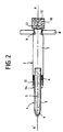
- FIG. 2 represents a first embodiment of the munition equipped with the device according to the invention.
- This munition has two parts: a front part 1 intended to damage a surface with high mechanical resistance, for example a concrete track, either by penetrating it preferably over its entire length, or by crossing it and exploding below it, and, a rear part 2 which may or may not be of diameter greater than that of the front part 1 and intended to provide a set of ballistic functions of the munition.
- a front part 1 intended to damage a surface with high mechanical resistance, for example a concrete track, either by penetrating it preferably over its entire length, or by crossing it and exploding below it
- a rear part 2 which may or may not be of diameter greater than that of the front part 1 and intended to provide a set of ballistic functions of the munition.
- the front part 1 is, for example, of cylindrical shape. It consists of an envelope 3, for example of steel, which ends at the front by a warhead 4, for example conical, and contains an explosive charge 5. Other elements can constitute the front part 1, for example a ballast allowing respectively to improve the penetrating power of the ammunition and to move the center of gravity of the ammunition or a priming rocket making it possible to trigger the explosion of the charge and which can be extended by a priming channel; these elements are not shown in Figure 1 and do not prevent the operation of the device according to the invention.
- the front part 1 of the ammunition extends, in the embodiment, inside the rear part 2 which thus covers it annularly.
- a fastening system 6 maintains the rear part 2 on the front part 1 so that the rear part 2 does not prevent the penetration of the front part 1 into the concrete track.
- the rear part 2 comprises, inter alia, a propellant 7 of which a part can engage in the annular space comprised between the front part 1 and the rear part 2, a tail made up of fins 8 fixed for example on the periphery of '' a nozzle 9 positioned at the rear of the propellant 7 and a braking system comprising, for example, a box 10 inside which is placed a parachute 11 and fixed to the nozzle 9 of the propellant 7, for example, by a unlockable mechanical fastening system 12.
- the thrust given by the retropulsor can be spread over a relatively long time with an earlier ignition date.
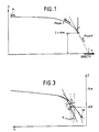
- FIG. 3 represents the comparison between the trajectory of a munition without back-propulsion SR and the trajectory of a munition with back-propulsion R.
- the device according to the invention applies to armor-piercing munitions for targets with high mechanical resistance, but it applies to all munitions having an almost vertical impact and whose minimum incidence is difficult to obtain by the sole use of a parachute.
- FIG. 4 represents the diagram of a first embodiment of the munition according to the invention.
- the munition has two parts: a front part 101 intended to damage a surface with high mechanical resistance, for example a concrete track, either by penetrating it preferably, over its entire length, or by crossing it and exploding in below and a rear portion 102 intended to provide a set of ballistic functions of the munition.
- This rear part 102 integral with the front part 101, before the impact of the ammunition on the target, is separated at the time of impact so as not to slow the penetration of the front part 101 into the target
- the front part 101 is, for example, of cylindrical shape. It consists of a casing 103, for example of steel, which ends at the front by a warhead 104, for example conical and at the rear, for example, by a priming rocket 105 placed behind an explosive charge 106 contained inside the envelope 103 and making it possible to trigger the explosion of the charge when the perforation is carried out, the initiation of the explosive charge being transmitted, for example to the front of the ammunition, by a channel d priming 150 to increase the destructive power of the ammunition.
- the outer surface of the envelope is, for example, smooth but it can be of any other shape, for example formed of grooves to, on the one hand, reduce the frictional forces during penetration and on the other hand increase the transverse stiffness of the ammunition to limit the flexion of the ammunition during the impact of the latter on the target.
- the front part 101 of the ammunition may include other elements. Indeed, in this figure 5, we find all the elements described in Figure 4 and constituting the ammunition. However, an additional element has been added to the front of the front part 101.
- This element constituting a ballast 107 is placed, for example, in the warhead 104 and on a part of the front part 101.
- This ballast 107 consisting of a dense material for example tungsten makes it possible, on the one hand, to improve the penetrating power of the front part 101 by increasing its mass, and, on the other hand, to reposition the center of gravity of the ammunition by moving it forward so as to reduce risks of rotation and bending of the ammunition at the time of impact on the target.
- the maximum diameter of the front part 101 has a value smaller than that of the rear part 102 so that the front part 101 extends inside the rear part 102. In this way the rear part 102 covers part of the part before 101 annularly.
- the penetration effect of the ammunition, in particular of the front part 101 being essentially due to the kinetic energy, it is essential to transmit the thrust force from the rear part 102 to the front part 101 during the first part of penetration.
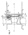
- the rear structure of the casing 103 of the front part 101 has, for example, a conical narrowing 108 on its periphery so that a fixing means, for example an asymmetrical fixing, for example a fixing ring 110 fixed to the rear part 102, for example, by laser welding after placing the propellant charge at a stop 113 of the fixing ring or by threading at this same stop, come into abutment on an oblique element 109 of the narrowing 108.
- a fixing means for example an asymmetrical fixing, for example a fixing ring 110 fixed to the rear part 102, for example, by laser welding after placing the propellant charge at a stop 113 of the fixing ring or by threading at this same stop, come into abutment on an oblique element 109 of the narrowing 108.
- This asymmetrical fixing makes it possible, on the one hand, to transmit the thrust from the rear part 102 of the ammunition to the front part 101 of the ammunition before the impact of the ammunition on the target, and, on the other hand to release, on impact of the ammunition on the target, the front part 101 of the rear part 102 to facilitate the penetration of the front part 101 of the ammunition in the target.
- This fixing ring 110 an embodiment of which is shown in detail in FIG. 6, makes it possible to secure the front part 101 of the rear part 102 by means of screws 111 positioned, for example, in holes 112, for example six in number, made in the ring 110.
- screws 111 penetrate inside the envelope 103 over a thickness E much less than the thickness of the envelope 103 to avoid any disturbance causing a deterioration of the front part 101.
- These screws 111 are, for example, shear screws which, when the munition penetrates the target, are sheared, thus allowing the front portion 101 to slide freely.
- the braking system 119 contains the parachute 124 not shown, the lines 125 of which are connected to one or more tie rods 126, for example, positioned at the internal periphery of the braking system 119; the tie rod (s) 126 are composed, for example, of a base 145 and a rod 128 so that, on the one hand, the rod 128 passes through the front 129 of the braking system 119 via , for example, a first cylindrical hole 130 positioned at the internal periphery of the braking system 119 and, on the other hand the base 145 rests on the front 129 of the braking system 119.
- a second cylindrical hole 131 has, for example, been machined on the rear 132 of the thruster 116 so that the tie rod 126 secures the braking system 119 on the divergent 122 of the propellant 116 by a nut 133 positioned on the threaded end of the rod 128; this nut 133 is supported for example on an element 134 for example solid, placed inside the second hole 131 whose diameter is different from the diameter of the first hole 130.
- the assembly 131, 133 and 134 is in one piece and is screwed into the base 145 by means of the threaded rod 128.
- the element 134 is held stationary in the rear 132 of the thruster 116 for example, by a ball 135 resting, for example, inside a groove 136 produced on the periphery of element 134; this ball 135 placed, for example, in a third cylindrical hole 137 perpendicular to a longitudinal axis X′X of the munition, is held pressed against the element 134, for example by a finger 138 placed in a fourth cylindrical hole parallel to the 'longitudinal axis XX ′ of the ammunition.
- This finger 138 is an element of a cover 139 for example circular, which ensures the closure of the divergent 122 of the rear 132 of the thruster 116; this cover 139 is held on the rear 132 of the thruster 116, for example, by four fingers 138 and also by shear screws 140, for example two in number, only one of which is shown in this figure. It is possible to use other fixing systems than the shear screws 140, for example clips or any other means.
- This cover 139 thus fixed on the rear 132 of the thruster 116 and secured to the fingers 138 preventing the escape of the balls 135 holding the tie rods 126 on which the lines 125 of the parachute 124 are fixed, is disconnected, at a determined moment, under the action of a pushing force which allows it to carry out a translational movement shearing on the one hand the screws 140 and driving the fingers 138 fixed to the latter which release the balls 135 unlocking the solid elements 134 and thus ensuring a translational movement along the axis X′X of the tie rods 126 which, once released, allow the separation or separation of the two modules consisting of a propellant 116 and a braking system.
- the translational movement of the cover 139 is produced, for example, along an axis substantially parallel to X′X.
- the thrust force separating the cover 139 is generated, for example, by gases coming, for example, from the propellant 116 when the latter is ignited.
- the use of this thruster 116 to give the necessary thrust force makes it possible to simplify the unlockable fixing system by using elements specific to the ammunition, in this case the gases of the thruster 116 having the initial function of giving the ammunition a speed determined to increase its efficiency, to trigger the separation of the elements.
- the box 123 of the braking system 119 has, for example, a square section to increase the available volume of the parachute necessary for obtaining a sufficiently low incidence of the ammunition; in the exemplary embodiment, the incidence is of the order of 30 °. To decrease this incidence, it would be necessary to increase the dimensions of the volume of the parachute which seems difficult taking into account the dimensions imposed for the ammunition.
- the square section of the box 123 also facilitates the storage of the ammunition inside the holds of an air vehicle which can for example be a stand-off cargo ship transporting the ammunition as shown in FIG. 8.
- This aerial vehicle 141 carries numerous munitions A, B, C comprising the various modules described above.
- Ammunition A comprises in its rear part the box 123 of square section containing the braking parachute not shown, the thruster whose casing 115 has for example a circular section and the tail unit comprising for example four fins 121 which, in the folded position , stay in the space between the envelope 115 and the square section prism of the box 123 and in its front part, the front part whose envelope 103 is cylindrical.
- the operation of the munition according to the invention, illustrated in FIG. 9, in an application intended for the deterioration of a horizontal target is as follows: the ammunition is dropped, for example, from an air vehicle on a concrete runway at soil 142 of thickness E and which must be deteriorated.
- This ammunition comprises the braking system 119 inside which is placed the parachute not shown, the tail 120 to ensure the balance of the ammunition.
- the triggering of the thruster 116 allows the release of the braking system 119 and the front part 101 extending into the thruster 116 and containing the explosive charge necessary for the deterioration of the target and not shown in this figure 9.
- phase II After a flight time in free fall, represented by phase I and where the ammunition is subjected to terrestrial gravitation, to air resistance and to the speed acquired during ejection, the braking parachute of the ammunition is deployed, in phase II , to influence the trajectory of the munition towards the target, in this case the concrete track 142.
- the braking system is separated from the munition according to phase III by means of the fixing device unlockable under the action of gases from propellant 116 which, on the other hand, make it possible to give the ammunition a speed necessary for the penetration of the front part 101 into the track at b Eton 142.
- phase IV during the impact of the front part 101 on the concrete track, the fixing ring, not shown, now maintaining the front part 101 to the rest of the ammunition, is detached leaving only the front part 101 of the ammunition in the concrete track, taking advantage of all the kinetic energy of the ammunition.
- the perforating power must be defined so that the penetration depth of the "center” of the explosion (in general the point of initiation of the explosive charge) is effectively at the "h” position.
- the arrangement of the modules in the ammunition according to the invention applies particularly to anti-track ammunition but can be used on any ammunition which must meet constraints of cost, carrying and employment and intended to perforate a target having a surface with high mechanical resistance before damaging it by explosion.
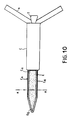
- FIG. 10 schematically represents another embodiment of the munition according to the invention.
- This munition essentially comprises two parts: a front body C A intended to perforate the material, for example concrete, forming the target, preferably penetrating it over its entire length, and a rear body C which may or may not be of diameter greater than that of the front body as shown in the figure.
- the rear body C comprises the various mechanical, electronic or pyrotechnic organs necessary for propelling, guiding, piloting or braking the ammunition; for this purpose it carries, for example, as shown in the figure, fins A forming a tail and a propulsion nozzle T.
- the front body C A is, in this embodiment, of substantially cylindrical shape and it is terminated at the front by a warhead O G , substantially conical.
- FIG. 11 represents a cross-section view, taken along an axis AA in the cylindrical part of the front body C A.
- the body C A is constituted by an envelope E of material having good mechanical resistance (steel, for example), enclosing an explosive charge C H.
- the outer surface of the envelope E, in its cylindrical part, has longitudinal grooves C N , preferably over its entire length.
- the grooves C N are represented in FIG. 2 as being of rectangular section but they can have other shapes, such as square, semi-circular, triangular, etc.
- the operation of the munition according to the invention is as follows.
- the kinetic energy imparted to the ammunition is such that it enables it to perforate the target concrete mass, typically an aerodrome runway, by sinking, preferably over the entire length of the body before C A.
- This perforation can in practice be a complete perforation of the thickness of concrete or, only, a semi-perforation.
- a priming rocket not shown for example contained in the rear body C, triggers the explosion of the charge C H.
- the splines C N produced in the body before C A have the effect in particular, on the one hand, of reducing the friction forces during the penetration of the body C A in the concrete and, on the other hand, to increase the transverse stiffness of the munition during the impact on the concrete, in order to reduce the risks of bending of the body before the engagement of the warhead.
- the parameters (dimensions, material) of the casing and of the grooves are chosen such that each of the grooves functions as a longitudinal hollow charge when the charge C H explodes, making thus a pre-fracturing of the concrete mass surrounding the body C A ; this allows the improvement of the mucking power of the amount of explosive charge contained in the ammunition and, consequently, the enlargement of the crater thus formed.
- Figure 12 shows a fractional cross-sectional view of an alternative embodiment of the grooved casing (E) of the front body (C A ) of the munition according to the invention.
- the inner surface of the envelope E also has longitudinal grooves, marked C I , alternated with the grooves C N.
- the dimensions of these grooves C I are chosen to promote the hollow load effect mentioned above.
- these extend over all or part of the warhead O G.
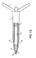
- FIG. 13 represents a diagram similar to that of FIG. 10, on which are illustrated various alternative embodiments of the munition according to the invention.
- the front body C A is formed by the casing E having splines C N and containing an explosive charge C H.
- the grooved front body C A which is recalled that it is intended to perforate the target concrete over its entire length, extends inside the rear body C, which thus covers it annularly.
- the attachment of the rear body C to the front body C A is then such that the body C does not appreciably oppose the penetration of the front body (C A ) into the target concrete.
- This variant has the advantage of increasing the length of the front body C A , for a given total length of ammunition, thereby notably increasing the amount of explosive charge C H or, conversely, of reducing the total length of the ammunition to length of body C A given: in fact, the annular space between the bodies C A and C can be used to arrange at least some of the elements which are contained in the body C.
- the rocket for initiating the load C H , marked F is placed in the front body C A , behind the load C H.
- the front part of the body C A namely the warhead O G and possibly a part of the cylindrical portion of the body C A
- a dense material L constituting a ballast.
- This material consists for example of tungsten.
- the presence of this ballast has the function, on the one hand, of improving the power of penetration of the body C A by increasing its mass, at given section, and, on the other hand, of displacing the center of gravity ammunition forward, which reduces the risk of tilting, bending and ricochet of the munition at the time of engagement of the warhead.
Landscapes
- Engineering & Computer Science (AREA)
- General Engineering & Computer Science (AREA)
- Physics & Mathematics (AREA)
- Fluid Mechanics (AREA)
- Chemical & Material Sciences (AREA)
- Combustion & Propulsion (AREA)
- Aviation & Aerospace Engineering (AREA)
- Aiming, Guidance, Guns With A Light Source, Armor, Camouflage, And Targets (AREA)
- Physical Vapour Deposition (AREA)
- Powder Metallurgy (AREA)
- Earth Drilling (AREA)
Applications Claiming Priority (6)
| Application Number | Priority Date | Filing Date | Title |
|---|---|---|---|
| FR9000431A FR2657158B1 (fr) | 1990-01-16 | 1990-01-16 | Munition perforante pour cible a haute resistance mecanique. |
| FR9000432A FR2657157B1 (fr) | 1990-01-16 | 1990-01-16 | Dispositif de correction de courbure d'un trajectoire d'une munition perforante pour des cibles a haute resistance mecanique. |
| FR9000430 | 1990-01-16 | ||
| FR9000430A FR2658283A1 (fr) | 1990-01-16 | 1990-01-16 | Munition perforante cannelee, notamment anti-beton. |
| FR9000431 | 1990-01-16 | ||
| FR9000432 | 1990-01-16 |
Publications (3)
| Publication Number | Publication Date |
|---|---|
| EP0438343A2 true EP0438343A2 (de) | 1991-07-24 |
| EP0438343A3 EP0438343A3 (en) | 1991-09-25 |
| EP0438343B1 EP0438343B1 (de) | 1998-07-22 |
Family
ID=27252118
Family Applications (1)
| Application Number | Title | Priority Date | Filing Date |
|---|---|---|---|
| EP91400072A Expired - Lifetime EP0438343B1 (de) | 1990-01-16 | 1991-01-15 | Penetratormunition für Ziele mit hohem mechanischem Widerstand |
Country Status (5)
| Country | Link |
|---|---|
| US (1) | US5189248A (de) |
| EP (1) | EP0438343B1 (de) |
| AT (1) | ATE168768T1 (de) |
| DE (1) | DE69129815T2 (de) |
| ES (1) | ES2118744T3 (de) |
Cited By (1)
| Publication number | Priority date | Publication date | Assignee | Title |
|---|---|---|---|---|
| FR2826441A1 (fr) * | 2001-06-22 | 2002-12-27 | Tdw Ges Fur Verteidigungstechn | Obus a fragmentations |
Families Citing this family (18)
| Publication number | Priority date | Publication date | Assignee | Title |
|---|---|---|---|---|
| DE4210113C1 (de) * | 1992-03-27 | 1998-11-05 | Athanassios Dr Ing Zacharias | Verfahren zum Leiten eines Flugkörpers und Flugkörper |
| DE19600167C1 (de) * | 1996-01-04 | 2003-07-17 | Diehl Stiftung & Co | Penetrator |
| RU2237856C2 (ru) * | 1999-03-25 | 2004-10-10 | Рафаел-Армамент Девелопмент Оторити Лтд. | Бронебойный реактивный снаряд |
| US6745696B1 (en) * | 1999-03-25 | 2004-06-08 | Rafael-Armament Development Authority Ltd. | Armor piercing projectile |
| US6276277B1 (en) | 1999-04-22 | 2001-08-21 | Lockheed Martin Corporation | Rocket-boosted guided hard target penetrator |
| US6494140B1 (en) | 1999-04-22 | 2002-12-17 | Lockheed Martin Corporation | Modular rocket boosted penetrating warhead |
| NO995142A (no) * | 1999-06-04 | 2000-10-16 | Nammo Raufoss As | Fremdriftsanordning for et prosjektil i et missil |
| NO995141A (no) | 1999-06-04 | 2000-10-16 | Nammo Raufoss As | Fremførings- og låsemekanisme i missil |
| EP1167914A1 (de) * | 2000-06-19 | 2002-01-02 | SM Schweizerische Munitionsunternehmung AG | Selbstangetriebenes Geschoss mit einem Durchschlagskern |
| FR2871226B1 (fr) * | 2004-06-08 | 2006-08-18 | Tda Armements Sas Soc Par Acti | Projectile, notamment bombe de penetration anti- infrastructure et procede de penetration d'un tel projectile a travers une paroi |
| RU2291375C1 (ru) * | 2005-07-08 | 2007-01-10 | Закрытое акционерное общество "Энергетика" | Кинетический артиллерийский снаряд |
| WO2008033170A2 (en) * | 2006-05-16 | 2008-03-20 | Textron Systems Corporation | Controlled dispense system for deployment of components into desired pattern and orientation |
| RU2352893C2 (ru) * | 2007-04-19 | 2009-04-20 | Николай Борисович Болотин | Автономный реактивный снаряд |
| RU2348895C2 (ru) * | 2007-05-03 | 2009-03-10 | Николай Борисович Болотин | Комбинированный реактивный снаряд |
| IL189612A (en) * | 2008-02-19 | 2012-10-31 | Rafael Advanced Defense Sys | Flammable arrowhead |
| RU2642197C2 (ru) * | 2016-07-01 | 2018-01-24 | Российская Федерация, от имени которой выступает Министерство промышленности и торговли Российской Федерации (Минпромторг России) | Высотный активно-реактивный снаряд и способ его функционирования |
| DE102016015042B4 (de) | 2016-12-16 | 2018-08-23 | Diehl Defence Gmbh & Co. Kg | Munitionsmodul, Gefechtskopf und Munition |
| SE2200029A1 (sv) * | 2022-03-15 | 2023-09-16 | Bae Systems Bofors Ab | Metod för samordnad brisad av projektiler |
Family Cites Families (19)
| Publication number | Priority date | Publication date | Assignee | Title |
|---|---|---|---|---|
| GB113975A (en) * | 1916-01-03 | 1918-03-21 | Robert Allen | Improvements in Explosive Shells or Projectiles. |
| GB329967A (en) * | 1929-02-27 | 1930-05-27 | Harry Bland Strang | Improvements in or relating to projectiles |
| US2356227A (en) * | 1940-08-27 | 1944-08-22 | Diehl Elias Stanley | Projectile |
| GB543950A (en) * | 1940-11-12 | 1942-03-20 | John William Flower | Improvements in or relating to aerial bombs |
| GB551515A (en) * | 1941-10-22 | 1943-02-25 | John Cook | Improvements in aerial bombs |
| US2539643A (en) * | 1946-05-08 | 1951-01-30 | William R Smythe | Apparatus for decelerating torpedoes |
| US2968244A (en) * | 1948-05-07 | 1961-01-17 | Jr Leo Maas | Jet accelerated missile |
| US2693327A (en) * | 1951-04-06 | 1954-11-02 | Mutual Corp | Aerial supply projectile brake mechanism |
| US3081704A (en) * | 1956-03-28 | 1963-03-19 | George T Boswell | Rod producing warhead |
| US3157123A (en) * | 1963-02-06 | 1964-11-17 | United Aircraft Corp | Retro-nozzle |
| DE1578089B1 (de) * | 1967-10-14 | 1975-07-03 | Messerschmitt Boelkow Blohm | Gefechtskopf fuer einen raketengetriebenen Flugkoerper oder ein Geschoss zur Bekaempfung von gepanzerten Zielen |
| US3438303A (en) * | 1966-11-30 | 1969-04-15 | Bombrini Parodi Delfino Spa | System including a tubular launching tube and a rocket provided with an outer auxiliary launching charge |
| GB1217465A (en) * | 1969-03-10 | 1970-12-31 | Israel State | Improvements in and relating to aerial flare bombs |
| FR2376300A1 (fr) * | 1976-12-28 | 1978-07-28 | Luchaire Sa | Dispositif pour la liaison entre deux etages d'un engin autopropulse |
| FR2479972A1 (fr) * | 1980-04-04 | 1981-10-09 | Pandelakis Jean Claude | Dispositif d'attaque d'objectifs destine a l'armement d'aeronefs et son procede d'utilisation |
| FR2517818A1 (fr) * | 1981-12-09 | 1983-06-10 | Thomson Brandt | Methode de guidage terminal et missile guide operant selon cette methode |
| US4573412A (en) * | 1984-04-27 | 1986-03-04 | The United States Of America As Represented By The Secretary Of The Army | Plug nozzle kinetic energy penetrator rocket |
| FR2619441B1 (fr) * | 1987-08-14 | 1993-05-07 | Thomson Brandt Armements | Bombe antipiste a haute perforation |
| US5080305A (en) * | 1990-04-16 | 1992-01-14 | Stencel Fred B | Low-altitude retro-rocket load landing system with wind drift counteraction |
-
1991
- 1991-01-15 ES ES91400072T patent/ES2118744T3/es not_active Expired - Lifetime
- 1991-01-15 DE DE69129815T patent/DE69129815T2/de not_active Expired - Fee Related
- 1991-01-15 EP EP91400072A patent/EP0438343B1/de not_active Expired - Lifetime
- 1991-01-15 AT AT91400072T patent/ATE168768T1/de not_active IP Right Cessation
- 1991-09-16 US US07/761,878 patent/US5189248A/en not_active Expired - Fee Related
Cited By (1)
| Publication number | Priority date | Publication date | Assignee | Title |
|---|---|---|---|---|
| FR2826441A1 (fr) * | 2001-06-22 | 2002-12-27 | Tdw Ges Fur Verteidigungstechn | Obus a fragmentations |
Also Published As
| Publication number | Publication date |
|---|---|
| EP0438343B1 (de) | 1998-07-22 |
| ES2118744T3 (es) | 1998-10-01 |
| US5189248A (en) | 1993-02-23 |
| DE69129815T2 (de) | 1998-12-03 |
| ATE168768T1 (de) | 1998-08-15 |
| DE69129815D1 (de) | 1998-08-27 |
| EP0438343A3 (en) | 1991-09-25 |
Similar Documents
| Publication | Publication Date | Title |
|---|---|---|
| EP0438343B1 (de) | Penetratormunition für Ziele mit hohem mechanischem Widerstand | |
| EP3102906B1 (de) | Hohlladung und verwendung zur trennung von zwei stockwerken eines luftfahrtfahrzeugs oder zur neutralisierung davon | |
| FR2526149A1 (fr) | Systeme d'arme et munition de survol | |
| FR2844348A1 (fr) | Munitions a bombe d'emploi universel et a cone de charge | |
| FR2535450A1 (fr) | Projectile perforant | |
| EP0457657B1 (de) | Durchdringendes Geschoss | |
| FR2609165A1 (fr) | Projectile comportant des sous-projectiles a zone d'efficacite predefinie | |
| EP0918205B1 (de) | Projektil mit radialer Wirkrichtung | |
| EP0799148B1 (de) | Aerodynamischer Bremsschild für Raumfahrzeug und damit ausgerüstete Satelliten | |
| EP1521053B1 (de) | Anti-Bunker Munition | |
| EP3589550B1 (de) | Verfahren und vorrichtung zum verbinden und linearen trennen zweier zusammengehaltener elemente | |
| EP0316216B1 (de) | Einrichtung zur Kreiselstabilisierung eines Geschoss-Steuerorgans | |
| FR2657158A1 (fr) | Munition perforante pour cible a haute resistance mecanique. | |
| EP1766323B1 (de) | Geschoss, insbesondere eine infrastruktur durchschlagende bombe und wanddurchschlagverfahren für das geschoss | |
| FR2657157A1 (fr) | Dispositif de correction de courbure d'un trajectoire d'une munition perforante pour des cibles a haute resistance mecanique. | |
| FR2769083A1 (fr) | Procede de guidage d'un missile et missile pour la mise en oeuvre du procede | |
| FR2669722A1 (fr) | Systeme d'arme agissant par attaque plongeante sur l'objectif. | |
| EP1000312B1 (de) | Munition für gegenmassnahmen | |
| FR2704052A1 (fr) | Charge formée multiamorçable. | |
| FR2712681A1 (fr) | Cone de charge de projectile. | |
| FR2601763A1 (fr) | Projectile sous-calibre de type fleche pour blindages actifs | |
| FR2650639A1 (fr) | Systeme de fixation deverrouillable pour deux elements notamment de munition | |
| EP1371935B1 (de) | Vorrichtung und Munition für den Schutz eines Fahrzeuges oder einer Plattform gegen Drohungen | |
| FR2508624A1 (fr) | Munition telle que grenade a main, en particulier pour la lutte contre les blindes | |
| EP0943887A1 (de) | Bausatz zum Umrüsten eines Sprenggeschosses auf ein Bentonstrukturen brechendes Geschoss, sowie ein derart umgerüstetes Geschoss |
Legal Events
| Date | Code | Title | Description |
|---|---|---|---|
| PUAI | Public reference made under article 153(3) epc to a published international application that has entered the european phase |
Free format text: ORIGINAL CODE: 0009012 |
|
| AK | Designated contracting states |
Kind code of ref document: A2 Designated state(s): AT BE CH DE ES FR GB GR IT LI LU NL SE |
|
| PUAL | Search report despatched |
Free format text: ORIGINAL CODE: 0009013 |
|
| AK | Designated contracting states |
Kind code of ref document: A3 Designated state(s): AT BE CH DE ES FR GB GR IT LI LU NL SE |
|
| 17P | Request for examination filed |
Effective date: 19920207 |
|
| 17Q | First examination report despatched |
Effective date: 19930611 |
|
| GRAG | Despatch of communication of intention to grant |
Free format text: ORIGINAL CODE: EPIDOS AGRA |
|
| GRAG | Despatch of communication of intention to grant |
Free format text: ORIGINAL CODE: EPIDOS AGRA |
|
| GRAG | Despatch of communication of intention to grant |
Free format text: ORIGINAL CODE: EPIDOS AGRA |
|
| GRAH | Despatch of communication of intention to grant a patent |
Free format text: ORIGINAL CODE: EPIDOS IGRA |
|
| RAP1 | Party data changed (applicant data changed or rights of an application transferred) |
Owner name: TDA ARMEMENTS S.A.S. |
|
| GRAH | Despatch of communication of intention to grant a patent |
Free format text: ORIGINAL CODE: EPIDOS IGRA |
|
| GRAA | (expected) grant |
Free format text: ORIGINAL CODE: 0009210 |
|
| AK | Designated contracting states |
Kind code of ref document: B1 Designated state(s): AT BE CH DE ES FR GB GR IT LI LU NL SE |
|
| PG25 | Lapsed in a contracting state [announced via postgrant information from national office to epo] |
Ref country code: NL Free format text: LAPSE BECAUSE OF FAILURE TO SUBMIT A TRANSLATION OF THE DESCRIPTION OR TO PAY THE FEE WITHIN THE PRESCRIBED TIME-LIMIT Effective date: 19980722 Ref country code: GR Free format text: LAPSE BECAUSE OF NON-PAYMENT OF DUE FEES Effective date: 19980722 Ref country code: AT Free format text: LAPSE BECAUSE OF FAILURE TO SUBMIT A TRANSLATION OF THE DESCRIPTION OR TO PAY THE FEE WITHIN THE PRESCRIBED TIME-LIMIT Effective date: 19980722 |
|
| REF | Corresponds to: |
Ref document number: 168768 Country of ref document: AT Date of ref document: 19980815 Kind code of ref document: T |
|
| ITF | It: translation for a ep patent filed | ||
| REG | Reference to a national code |
Ref country code: CH Ref legal event code: EP |
|
| REF | Corresponds to: |
Ref document number: 69129815 Country of ref document: DE Date of ref document: 19980827 |
|
| REG | Reference to a national code |
Ref country code: ES Ref legal event code: FG2A Ref document number: 2118744 Country of ref document: ES Kind code of ref document: T3 |
|
| GBT | Gb: translation of ep patent filed (gb section 77(6)(a)/1977) |
Effective date: 19980922 |
|
| NLV1 | Nl: lapsed or annulled due to failure to fulfill the requirements of art. 29p and 29m of the patents act | ||
| PG25 | Lapsed in a contracting state [announced via postgrant information from national office to epo] |
Ref country code: LU Free format text: LAPSE BECAUSE OF NON-PAYMENT OF DUE FEES Effective date: 19990115 |
|
| PG25 | Lapsed in a contracting state [announced via postgrant information from national office to epo] |
Ref country code: LI Free format text: LAPSE BECAUSE OF NON-PAYMENT OF DUE FEES Effective date: 19990131 Ref country code: CH Free format text: LAPSE BECAUSE OF NON-PAYMENT OF DUE FEES Effective date: 19990131 Ref country code: BE Free format text: LAPSE BECAUSE OF NON-PAYMENT OF DUE FEES Effective date: 19990131 |
|
| RAP4 | Party data changed (patent owner data changed or rights of a patent transferred) |
Owner name: TDA ARMEMENTS S.A.S. |
|
| PLBE | No opposition filed within time limit |
Free format text: ORIGINAL CODE: 0009261 |
|
| STAA | Information on the status of an ep patent application or granted ep patent |
Free format text: STATUS: NO OPPOSITION FILED WITHIN TIME LIMIT |
|
| 26N | No opposition filed | ||
| BERE | Be: lapsed |
Owner name: TDA ARMEMENTS S.A.S. Effective date: 19990131 |
|
| REG | Reference to a national code |
Ref country code: CH Ref legal event code: PL |
|
| PGFP | Annual fee paid to national office [announced via postgrant information from national office to epo] |
Ref country code: GB Payment date: 20001222 Year of fee payment: 11 |
|
| PGFP | Annual fee paid to national office [announced via postgrant information from national office to epo] |
Ref country code: DE Payment date: 20001227 Year of fee payment: 11 |
|
| PGFP | Annual fee paid to national office [announced via postgrant information from national office to epo] |
Ref country code: SE Payment date: 20001228 Year of fee payment: 11 |
|
| PGFP | Annual fee paid to national office [announced via postgrant information from national office to epo] |
Ref country code: ES Payment date: 20010117 Year of fee payment: 11 |
|
| PGFP | Annual fee paid to national office [announced via postgrant information from national office to epo] |
Ref country code: FR Payment date: 20010126 Year of fee payment: 11 |
|
| REG | Reference to a national code |
Ref country code: GB Ref legal event code: IF02 |
|
| PG25 | Lapsed in a contracting state [announced via postgrant information from national office to epo] |
Ref country code: GB Free format text: LAPSE BECAUSE OF NON-PAYMENT OF DUE FEES Effective date: 20020115 |
|
| PG25 | Lapsed in a contracting state [announced via postgrant information from national office to epo] |
Ref country code: SE Free format text: LAPSE BECAUSE OF NON-PAYMENT OF DUE FEES Effective date: 20020116 Ref country code: ES Free format text: LAPSE BECAUSE OF NON-PAYMENT OF DUE FEES Effective date: 20020116 |
|
| PG25 | Lapsed in a contracting state [announced via postgrant information from national office to epo] |
Ref country code: DE Free format text: LAPSE BECAUSE OF NON-PAYMENT OF DUE FEES Effective date: 20020801 |
|
| EUG | Se: european patent has lapsed |
Ref document number: 91400072.4 |
|
| GBPC | Gb: european patent ceased through non-payment of renewal fee |
Effective date: 20020115 |
|
| PG25 | Lapsed in a contracting state [announced via postgrant information from national office to epo] |
Ref country code: FR Free format text: LAPSE BECAUSE OF NON-PAYMENT OF DUE FEES Effective date: 20020930 |
|
| REG | Reference to a national code |
Ref country code: FR Ref legal event code: ST |
|
| REG | Reference to a national code |
Ref country code: ES Ref legal event code: FD2A Effective date: 20030211 |
|
| PG25 | Lapsed in a contracting state [announced via postgrant information from national office to epo] |
Ref country code: IT Free format text: LAPSE BECAUSE OF NON-PAYMENT OF DUE FEES;WARNING: LAPSES OF ITALIAN PATENTS WITH EFFECTIVE DATE BEFORE 2007 MAY HAVE OCCURRED AT ANY TIME BEFORE 2007. THE CORRECT EFFECTIVE DATE MAY BE DIFFERENT FROM THE ONE RECORDED. Effective date: 20050115 |