EP0438346A1 - Verbesserte spiralnutenförmig verlaufende gasgeschmierte Dichtung - Google Patents
Verbesserte spiralnutenförmig verlaufende gasgeschmierte Dichtung Download PDFInfo
- Publication number
- EP0438346A1 EP0438346A1 EP91400081A EP91400081A EP0438346A1 EP 0438346 A1 EP0438346 A1 EP 0438346A1 EP 91400081 A EP91400081 A EP 91400081A EP 91400081 A EP91400081 A EP 91400081A EP 0438346 A1 EP0438346 A1 EP 0438346A1
- Authority
- EP
- European Patent Office
- Prior art keywords
- seal ring
- rotary seal
- annular
- rotary
- Prior art date
- Legal status (The legal status is an assumption and is not a legal conclusion. Google has not performed a legal analysis and makes no representation as to the accuracy of the status listed.)
- Granted
Links
- 238000007789 sealing Methods 0.000 claims abstract description 56
- 239000000463 material Substances 0.000 claims description 4
- 230000037361 pathway Effects 0.000 claims 7
- 238000013022 venting Methods 0.000 claims 4
- 239000012530 fluid Substances 0.000 claims 2
- 239000007789 gas Substances 0.000 description 59
- 230000002706 hydrostatic effect Effects 0.000 description 12
- 229910052751 metal Inorganic materials 0.000 description 6
- 239000002184 metal Substances 0.000 description 6
- OKTJSMMVPCPJKN-UHFFFAOYSA-N Carbon Chemical compound [C] OKTJSMMVPCPJKN-UHFFFAOYSA-N 0.000 description 5
- 230000008901 benefit Effects 0.000 description 5
- 238000000034 method Methods 0.000 description 5
- 239000003921 oil Substances 0.000 description 5
- 238000005086 pumping Methods 0.000 description 5
- 230000009471 action Effects 0.000 description 4
- 238000013461 design Methods 0.000 description 4
- 230000006872 improvement Effects 0.000 description 4
- 238000000926 separation method Methods 0.000 description 4
- 239000010935 stainless steel Substances 0.000 description 4
- 229910001220 stainless steel Inorganic materials 0.000 description 4
- 229910052799 carbon Inorganic materials 0.000 description 3
- 238000001816 cooling Methods 0.000 description 3
- 229910001119 inconels 625 Inorganic materials 0.000 description 3
- 238000002955 isolation Methods 0.000 description 3
- 230000033001 locomotion Effects 0.000 description 3
- 230000008569 process Effects 0.000 description 3
- HBMJWWWQQXIZIP-UHFFFAOYSA-N silicon carbide Chemical compound [Si+]#[C-] HBMJWWWQQXIZIP-UHFFFAOYSA-N 0.000 description 3
- 229910010271 silicon carbide Inorganic materials 0.000 description 3
- 239000000969 carrier Substances 0.000 description 2
- 238000013016 damping Methods 0.000 description 2
- 230000000694 effects Effects 0.000 description 2
- 229910002804 graphite Inorganic materials 0.000 description 2
- 239000010439 graphite Substances 0.000 description 2
- 150000002739 metals Chemical class 0.000 description 2
- 230000008439 repair process Effects 0.000 description 2
- 229910000639 Spring steel Inorganic materials 0.000 description 1
- 230000002411 adverse Effects 0.000 description 1
- 229910045601 alloy Inorganic materials 0.000 description 1
- 239000000956 alloy Substances 0.000 description 1
- 238000000429 assembly Methods 0.000 description 1
- 230000000712 assembly Effects 0.000 description 1
- 230000009286 beneficial effect Effects 0.000 description 1
- 239000012876 carrier material Substances 0.000 description 1
- 230000008859 change Effects 0.000 description 1
- 238000004140 cleaning Methods 0.000 description 1
- 238000005094 computer simulation Methods 0.000 description 1
- 238000010276 construction Methods 0.000 description 1
- 230000007797 corrosion Effects 0.000 description 1
- 238000005260 corrosion Methods 0.000 description 1
- 238000005336 cracking Methods 0.000 description 1
- 238000002474 experimental method Methods 0.000 description 1
- 238000004880 explosion Methods 0.000 description 1
- 238000009434 installation Methods 0.000 description 1
- 239000000203 mixture Substances 0.000 description 1
- 238000012986 modification Methods 0.000 description 1
- 230000004048 modification Effects 0.000 description 1
- 238000005457 optimization Methods 0.000 description 1
- 230000010355 oscillation Effects 0.000 description 1
- 239000007787 solid Substances 0.000 description 1
- 238000012546 transfer Methods 0.000 description 1
- UONOETXJSWQNOL-UHFFFAOYSA-N tungsten carbide Chemical compound [W+]#[C-] UONOETXJSWQNOL-UHFFFAOYSA-N 0.000 description 1
Images


Classifications
-
- F—MECHANICAL ENGINEERING; LIGHTING; HEATING; WEAPONS; BLASTING
- F16—ENGINEERING ELEMENTS AND UNITS; GENERAL MEASURES FOR PRODUCING AND MAINTAINING EFFECTIVE FUNCTIONING OF MACHINES OR INSTALLATIONS; THERMAL INSULATION IN GENERAL
- F16J—PISTONS; CYLINDERS; SEALINGS
- F16J15/00—Sealings
- F16J15/16—Sealings between relatively-moving surfaces
- F16J15/34—Sealings between relatively-moving surfaces with slip-ring pressed against a more or less radial face on one member
- F16J15/3404—Sealings between relatively-moving surfaces with slip-ring pressed against a more or less radial face on one member and characterised by parts or details relating to lubrication, cooling or venting of the seal
- F16J15/3408—Sealings between relatively-moving surfaces with slip-ring pressed against a more or less radial face on one member and characterised by parts or details relating to lubrication, cooling or venting of the seal at least one ring having an uneven slipping surface
- F16J15/3412—Sealings between relatively-moving surfaces with slip-ring pressed against a more or less radial face on one member and characterised by parts or details relating to lubrication, cooling or venting of the seal at least one ring having an uneven slipping surface with cavities
Definitions
- the present invention relates to a gas seal, and more specifically, to a gas seal with spiral grooves.
- Dry-running gas lubricated seals provide significant economic benefits over the prior art oil seals which consume significantly more power due to the greater viscosity of oil as compared to gas. Furthermore gas seals do not require expensive apparatus for cleaning and cooling the oil.
- a "O" ring is placed between the stationary seal ring and the stationary seal ring carrier, and the seal ring is typically manufactured from materials having low thermal expansion coefficients, such as carbon graphite, silicon carbide and tungsten carbide.
- the ring carrier in such a conventional gas seal is fabricated from metal, such as stainless steel, Inconel 625 or another metal having good corrosion resistance, temperature resistance and the required strength. These metals from which the carriers are formed have coefficients of expansion approximately three times that of the typical seal ring materials.
- the seal rings are mounted within a stationary housing and mounted over a metal balance diameter which serves to center the seal ring with a clearance used to compensate for differential thermal growth between the seal ring and the balance diameter.
- a metal balance diameter which serves to center the seal ring with a clearance used to compensate for differential thermal growth between the seal ring and the balance diameter.
- a diametrical clearance of .015 to .019 inches would be common.
- the seal assembly becomes hot, with temperatures up to 350 to 400°F not uncommon. When the assembly heats, the balance diameter expands relative to the seal ring and then centers the seal ring.
- a further problem of dynamic tracking is associated with placement of the seal ring carrier on a high speed shaft.
- an alloy such as 4340 is used for the shaft itself which has a different thermal expansion coefficient than the rotary ring carrier.
- the loosening of the rotary seal ring carrier on the shaft is of greater concern due to the high speed of rotation.
- approximately .003 inches loosening at 400°F results from differential thermal expansion.
- a ten pound carrier creates centrifugal unbalanced force of 218 pounds.
- shrink fits have often been used to secure seal carriers on a rotating shaft in order to eliminate the loosening due to thermal and centrifugal effects.
- shrink fit makes installation and removal of seal assemblies very difficult in many cases.
- a final area of sub-optimal performance in current gas seal design relates to the safety problems present in conventional gas seals.
- a conventional seal holds the rotary seal ring with pins passing from the rotary seal ring carrier into the seal ring.
- the pins can cause significant stress concentration in the rotary seal ring and lead to fracture of the ring.
- the problem is accentuated in the conventional gas seal design by the lack of any retaining structure for the rotary seal ring should catastrophic failure occur.
- a fractured ring can cause significant damage to the machine in which it is operating as well as expensive down time in repair.
- An object of the invention is to provide an improved gas seal.
- a further object is to provide a seal operating on a thinner gas film and having less leakage.
- a still further object of the invention is to provide increased dynamic tracking capability of the sealing faces. It is still a further object of the invention to provide a superior and safer means for retaining the rotary seal ring.
- the invention comprises a dry running gas seal for sealing along a shaft within a machine body, the seal comprising: a stationary seal ring carrier attached to the machine body, the stationary seal ring carrier having an annular pocket having walls; a stationary seal ring held in the pocket of the stationary seal ring carrier; a rotary seal ring carrier fixedly attached to the shaft, the rotary ring carrier having an annular pocket having walls; a rotary seal ring held in the pocket of the rotary seal ring carrier, the rotary seal ring having sealing face held adjacent to the stationary seal ring; and grooves formed on the sealing face of the rotary seal ring, wherein the grooves have an average angle of 5 to 15 degrees.
- the seal further comprises: an annular notch formed in a portion of the stationary seal ring axially away from the rotary seal ring; an insert having an axially parallel portion and an axially orthogonal portion, the axially orthogonal portion extending into the notch; and an "O" ring disposed between the axially orthogonal portion and one of the walls of the pocket in the stationary seal ring carrier.
- the seal further comprises: an annular groove formed in a radially inner one of the walls of the rotary seal ring carrier; and a finger spring disposed in the groove.
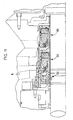
- Figure 1 is a partial cross-section of a gas seal according to the invention.
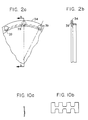
- Figure 2 (a) and (b) depict an "O" ring holder according to the invention.
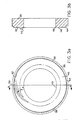
- Figure 3 (a) and (b) depict a rotary seal ring as used in the seal of Fig. 1.
- Figure 4 is a graphic representation of hydrostatic opening forces.
- Figure 5 is a graphic representation of hydrodynamic opening forces.
- Figure 6 is a typical force vs. clearance graph.
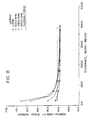
- Figure 7 is a force vs. clearance graph for a 7° spiral groove angle.
- Figure 8 is a force vs. clearance graph for a 15° spiral groove angle.
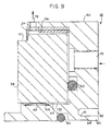
- Figure 9 is a detailed partial cross-sectional view of a rotary seal ring and carrier according to the invention.
- Figures 10 (a) and (b) depict a finger spring.
- Figure 11 is a partial cross sectional view of a tandem sealing system using two gas seals according to the invention.
- Figure 1 shows a dry-running gas seal shown generally as 10, including stationary seal ring assembly 12 attached to machine body 14 and rotary seal ring assembly 16 attached to the rotary shaft 18.
- the gas seal is used to seal a process gas (indicated as "Hp” in fig. 1) on the radially tward side of the seal from a low pressure area (indicated as "Lp” in fig. 1) on the radially inward side of the seal.
- Stationary seal ring assembly 12 includes stationary seal ring 20, which is usually made of carbon graphite.
- the stationary seal ring has annular notch 22 formed in the radially inner back portion.
- Stationary seal ring housing 24, which holds the stationary seal ring in annular pocket 26, is preferably made of Inconel 625 or stainless steel.
- the pocket may be formed by turning or other methods well known in the art.
- a series of holes 28 are bored into the bottom of pocket 26. Springs 30 fit into those bore holes and serve to engage sealing face 32 with the rotary seal ring assembly when the seal is not pressurized.
- an "O" ring holder is incorporated into the stationary seal ring assembly which minimizes the drag placed on the stationary seal ring by the "O" ring and thus enhances dynamic tracking capability.
- the assembly 12 includes “O” ring holder 34 and “O” ring 36.
- Figure 2 shows an enlarged view of the holder 34.
- the holder incorporates circular pockets 39 for the purpose of guiding springs 30 between the holes 28 of the stationary seal ring carrier 24 and the stationary seal ring 20.
- Holder 34 has a "T" shaped cross-section which enhances the stiffness of the holder and allows the thickness to be reduced.
- the "T" shaped "O" ring holder includes an axially orthogonal portion against which springs 30 act and an axially parallel portion which is perpendicular to the orthogonal portion and extends into the notch 22.
- the "T" shape allows the mass and momentum to be reduced and dynamic tracking improved.
- the "O" ring holder extends into notch 22 and allows the stationary seal ring 20 to axially overlap the "O" ring 36, thereby improving axial compactness of the assembly. Additionally, the “O” ring holder improves dynamic tracking.
- the "O” ring is radially squeezed between two metal sections having the same or approximately the same coefficients of thermal expansion.
- "O" ring holder 34 and seal ring housing 24 are made of the same or similar metals. The thermal expansion of the metallic pieces therefore does not create a change in the "O" ring radial squeeze. Therefore, a very light original radial squeeze, typically 4 to 7% of the "O" ring cross section, may be used. This reduces the axial drag forces imparted by the "O" ring holder to the stationary seal ring and thus enhances dynamic tracking capability.
- a small clearance is placed between the outer wall of the axially parallel portion of the "O" ring holder 34 and the wall of the notch 22 of the stationary seal ring 20 so that there is no friction between the surfaces and so that the holder cannot pull on the seal ring.
- the "O" ring 36 is radially squeezed between the holder 34 and the housing 24 and effectively holds the holder in place and keeps it spaced from the seal ring. Therefore, for any axial vibration or run out of the rotating ring assembly 16, the stationary seal ring is free to move forward and is not axially constrained by friction or by "O" ring forces, which are relatively high.
- the design for the new "O" ring holder provides another beneficial feature. If the stationary seal ring 20 moves forward in order to accommodate rotating seal ring assembly motion and thereby separates slightly from the “O” ring, gas will flow between the "O" ring holder and the back of the seal ring and briefly beyond the “O” ring. Associated with this gas flow would be a pressure drop, and thus, there would be a hydrostatic pressure differential, in the axial direction which would cause the "O" ring holder and the "O” ring to almost instantly move forward to follow the axial motion of the seal ring. The magnitude of this available force is such that there would be no significant separation between the stationary seal ring and the "O” ring for any appreciable period of time.
- the rotary seal assembly 16 has a rotary seal ring 38 and a rotary seal carrier 40 for holding the seal ring.
- the rotary seal ring is typically made of silicon carbide.
- the face of the rotary seal ring in the rotary seal ring assembly has spiral grooves 42 formed thereon.
- the grooves serve to provide both hydrostatic and hydrodynamic forces for separating the sealing faces. When exposed to a pressurized gas, the gas enters the grooves and provides an opening force. That opening force is balanced by the gas pressure acting on the back of the seal ring which tends to close the sealing faces.
- Figure 4 shows a representation of the hydrostatic forces on a non-rotating seal as a function of clearance between the sealing faces. Once the shaft begins to rotate, the grooves perform a pumping function which increases the pressure and pressure variation across the sealing faces, and thus increases the opening force as compared to the hydrostatic case.
- Figure 5 shows a typical hydrodynamic pressure profile for differing seal face clearances.
- the difference between the clearances is reduced by the optimization of the groove parameters.
- Maximum pumping action occurs when the average groove angle d, as shown in Figure 3, is at approximately 30°.
- the greater the pumping action the greater the additional hydrodynamic opening force as compared to hydrostatic opening force. It is therefore desirable to reduce the difference between the hydrodynamic and hydrostatic opening forces by selection of a spiral groove angle d which is not at the optimum pumping angle. Therefore, a low angle in the range of 5-15° or a high angle in the range of 60-85° is desirable.
- a high angle has the added benefit of improving the bi-directionality of the seal.
- the grooves extended from the outside diameter 44 of the seal face 46 56% of the way across the sealing face toward the inside diameter 48.
- the remainder of the sealing face constituted dam 50, shown in Figure 3.
- the groove depth was 300 micro inches, and the average groove angle 7°.
- the steady state clearance at 5,000 rpm was approximately 45 micro inches and at 16,000 rpm approximately 60 micro inches, as shown in Figure 7.
- the leakage at 5,000 rpm was approximately .4 scfm, and the leakage at 16,000 rpm was approximately .9 scfm.
- the average groove angle was 15°
- the grooves extended across 60% of the sealing face
- the groove depth was 350 micro inches.
- the seal faces have a clearance of approximately 90 micro inches at 5,000 rpm and approximately 140 micro inches at 16,000 rpm, as shown in figure 8.
- the leakage at 1300 psig and 5,000 rpm was approximately 1.5 scfm
- the leakage at 16,000 rpm was approximately 6.0 scfm.
- a device for holding the rotary seal ring in a rotary seal ring carrier is provided in the seal.
- the rotary seal ring carrier 40 of this invention is annular and has a pocket 52 with walls which surround the rotary seal ring 38.
- a cross-sectionally L-shaped annular spring clip press fits into the pocket, against the outer wall of the pocket and over the rotary seal ring.
- the L-shaped spring clip has radially inward protruding dents 56 formed therein which fit into grooves 58 (shown in Figure 3) formed in the rotary seal ring.
- a portion of the L-shaped clip extends over a notch 60 formed in the outer edge of the rotary seal ring.
- the clip serves to press the seal ring against the "O" ring 62 positioned at the back of pocket 52.
- Dents 56 provide a dent drive which prevents the rotary seal ring from rotating within the rotary seal ring carrier.
- the pocket and the L-shaped spring clip provide a method of retaining the rotary seal ring should catastrophic failure occur by preventing the rotary seal ring from escaping the pocket and damaging the machine. Thus, in the event of rotary seal ring failure, only replacement of the seal is required and not repair of machine components.
- an apparatus for centering the rotary seal ring within the rotary seal ring carrier. If the seal ring abutted the inner wall 64 of the pocket 52 (i.e., the balance diameter) with no clearance, differential thermal expansion between the rotary seal ring material, usually silicon carbide, and the rotary seal ring carrier material, usually stainless steel or Inconel 625, would cause cracking of the rotary seal ring. Therefore, in this invention, an annular groove 66 is formed in the inner wall of the pocket and a finger spring 68 is placed in that groove. The finger spring, which is discussed in greater detail below, ensures that the rotary seal ring is centered within the seal ring carrier and that rotary seal ring does not crack as the rotary seal ring carrier expands relative to it.
- the rotary seal assembly 15 also includes rotary seal ring carrier 40 having annular surface 70 extending from the carrier along shaft 18.
- the radially inner surface has a pair of annular pockets 72 formed at the front and rear of the annular surface 70.
- Finger springs 74 are located in those pockets.
- Figure 10 depicts a finger spring.
- the spring is preferably made of spring steel and should be designed to have the proper radial stiffness for the weight of the carrier at maximum operating speed.
- the stiffness is preferably four to ten times the centrifugal unbalance force, per unit radial deflection.
- the spring stiffness should be about 160 to 400 lbs. per .001 inch deflection.
- the means of maintaining fit of the rotary ring carrier may comprise a spring portion 80 of the rotary seal ring carrier 40, as shown in figure 9.
- the spring portion is formed by creating an annular undercut region 82 in the carrier. Lip 84 serves to press against the shaft and compress portion 80, thus providing a spring fit to the shaft.
- the spring portion 80 may be segmented in to multiple arc-like sections by a series of radial cuts 81. Since the majority of the mass of the rotary ring carrier is near the spring portion, no additional means for maintaining fit is required.
- an "O" ring 85 is used which is disposed in a groove in the inner surface of the rotary Seal ring carrier.
- the rotary seal ring carrier may be provided with improved thermal isolation from the shaft. Thermal isolation is accomplished by an annular undercut 86 in annular surface 70. The undercut allows an insulating layer of air to exist between shaft 18 and carrier 40, and additionally, reduces the contact area between the shaft and the carrier. Thereby, the heat transfer is reduced.
- an apparatus for cooling the rotary seal ring within its "cup type" retainer in order to reduce heat distortion of the sealing faces.
- a typical gas seal of the invention running at high speed and pressure could reach a temperature of approximately 400°F in the gas adjacent to the retainer.
- the actual seal ring could get even hotter as it is somewhat insulated by the retainer.
- the cooling apparatus consists of a series of holes 76 in the rotary seal ring carrier 40. These holes are slanted toward the direction of rotation at an angle of 35°to 45° from the plane of rotation. This orientation pumps gas into and around the back of the rotary seal ring and out vent holes 78 which are provided in the side of the rotary seal ring carrier.
- 6 to 8 holes are provide which are circular in cross-section with a 1/4 to 3/8 inch diameter.
- vent openings may be provided in the axially orthogonal part of the "L" shaped spring clip 54.
- Figure 11 shows a tandem gas seal with a pressure step down across the first seal to the second seal.
- first gas seal 88 may use a low groove angle such as 7°
- second seal 90 uses a slightly larger groove angle such as 15°.
- a ball check valve should be provided to insure that the gas pressure between the seals does not exceed the process gas pressure.
- a segmented carbon seal 92 is provided as a leakage control seal.
- a buffer gas may be injected between two gas seals in a face to face mounting arrangement.
- the buffer gas is particularly useful if the process gas is dirty or abrasive.
- a safety feature which may be incorporated into the design of a gas seal is a labyrinth seal 94 (shown in figure 1) which is included along the seal and near a vent to stack.
- the labyrinth seal provides a tortuous path for the gas to follow should a failure in the gas seal occur.
- the labyrinth seal should have a flow of one-tenth or less that of the vent stack through which the gas can be disposed. In a case of catastrophic failure of the gas seal, the hot gases can be vented rather than rushing through the seal into oil. Without a labyrinth seal, a mixture of oxygenated gas entering the oil can result in a sudden explosion.
Landscapes
- Engineering & Computer Science (AREA)
- General Engineering & Computer Science (AREA)
- Mechanical Engineering (AREA)
- Mechanical Sealing (AREA)
- Sealing Devices (AREA)
- Lubricants (AREA)
Applications Claiming Priority (2)
| Application Number | Priority Date | Filing Date | Title |
|---|---|---|---|
| US466656 | 1990-01-17 | ||
| US07/466,656 US5039113A (en) | 1990-01-17 | 1990-01-17 | Spiral groove gas lubricated seal |
Publications (2)
| Publication Number | Publication Date |
|---|---|
| EP0438346A1 true EP0438346A1 (de) | 1991-07-24 |
| EP0438346B1 EP0438346B1 (de) | 1995-12-20 |
Family
ID=23852608
Family Applications (1)
| Application Number | Title | Priority Date | Filing Date |
|---|---|---|---|
| EP91400081A Expired - Lifetime EP0438346B1 (de) | 1990-01-17 | 1991-01-15 | Verbesserte spiralnutenförmig verlaufende gasgeschmierte Dichtung |
Country Status (5)
| Country | Link |
|---|---|
| US (1) | US5039113A (de) |
| EP (1) | EP0438346B1 (de) |
| JP (1) | JPH0599345A (de) |
| AT (1) | ATE131916T1 (de) |
| DE (1) | DE69115510T2 (de) |
Cited By (7)
| Publication number | Priority date | Publication date | Assignee | Title |
|---|---|---|---|---|
| EP1079156A1 (de) * | 1999-08-16 | 2001-02-28 | Nippon Pillar Packing Co., Ltd. | Berührungsfreie, mechanische Dichtung |
| CN103438217A (zh) * | 2013-09-11 | 2013-12-11 | 山东天力干燥股份有限公司 | 一种万向旋转动密封装置及回转设备 |
| US8715835B2 (en) | 2009-02-26 | 2014-05-06 | John Crane Uk Limited | Tolerance strips |
| WO2015061132A1 (en) | 2013-10-22 | 2015-04-30 | United Technologies Corporation | Piloted retaining plate for a face seal arrangement |
| CN105143735A (zh) * | 2012-12-07 | 2015-12-09 | 彻斯特顿公司 | 具有轴向偏压组件的剖分式机械密封件 |
| US11608898B2 (en) | 2020-06-05 | 2023-03-21 | A.W. Chesterton Company | Externally energized secondary seals in split mechanical seals |
| US12152677B2 (en) | 2020-06-05 | 2024-11-26 | A.W. Chesterton Company | System and method for optimizing a fluid environment in split mechanical seals |
Families Citing this family (59)
| Publication number | Priority date | Publication date | Assignee | Title |
|---|---|---|---|---|
| JPH0756345B2 (ja) * | 1990-07-09 | 1995-06-14 | 株式会社荏原製作所 | 非接触端面シール |
| DE4303050B4 (de) * | 1992-02-26 | 2004-02-26 | Sedy, Josef, Mt. Prospect | Gleitringdichtung |
| US5722665A (en) * | 1992-02-26 | 1998-03-03 | Durametallic Corporation | Spiral groove face seal |
| DE69310245T2 (de) * | 1992-02-28 | 1997-08-14 | Sealol | Zentrierfeder für zwei ringförmige Körper |
| US5632435A (en) * | 1992-05-27 | 1997-05-27 | Sulzer-Escher Wyss Ag | Process for the production of a soldered joint |
| US5533739A (en) * | 1992-06-10 | 1996-07-09 | Durametallic Corporation | Non-contacting seal with centering spring mounted in dovetailed grooved |
| JP3318389B2 (ja) * | 1992-09-02 | 2002-08-26 | フロウサーヴ・マネジメント・カンパニー | メカニカルシール組立体 |
| US5370403A (en) * | 1992-12-16 | 1994-12-06 | Durametallic Corporation | Non-contacting face seal |
| US5388843A (en) * | 1993-02-16 | 1995-02-14 | Durametallic Corporation | Fluid film seal |
| CA2147739A1 (en) * | 1993-08-26 | 1995-03-02 | Josef Sedy | Face seal with double groove arrangement |
| US5498007A (en) * | 1994-02-01 | 1996-03-12 | Durametallic Corporation | Double gas barrier seal |
| US5551708A (en) * | 1994-06-29 | 1996-09-03 | Durametallic Corporation | Face ring retainer arrangement for mechanical seal |
| US5558342A (en) * | 1994-08-05 | 1996-09-24 | Durametallic Corporation | Mechanical seal with spring drive |
| AU4138796A (en) * | 1994-11-01 | 1996-05-23 | Russell Douglas Ide | Dampened dry running gas seal |
| US5639097A (en) * | 1994-12-09 | 1997-06-17 | Eg&G Sealol, Inc. | Gas seal "O" ring holder |
| US5538257A (en) * | 1994-12-30 | 1996-07-23 | Eg&G Sealol, Inc. | Spring device and method for holding a component on a shaft and pusher seal assembly using same |
| GB9508034D0 (en) * | 1995-04-20 | 1995-06-07 | Dresser Rand Co | A shaft seal |
| US5769604A (en) * | 1995-05-04 | 1998-06-23 | Eg&G Sealol, Inc. | Face seal device having high angular compliance |
| US5941532A (en) | 1996-06-20 | 1999-08-24 | Rexnord Corporation | Aerospace housing and shaft assembly with noncontacting seal |
| SE518871C2 (sv) * | 1996-11-14 | 2002-12-03 | Flygt Ab Itt | Plantätningsarrangemang |
| US6116609A (en) * | 1997-12-17 | 2000-09-12 | A. W. Chesterton Company | Fluidic feedback pressure regulation system for a mechanical seal |
| US6068263A (en) * | 1997-12-17 | 2000-05-30 | A.W. Chesterton Company | Split mechanical face seal with resilient pivoting member |
| US6068264A (en) * | 1997-12-17 | 2000-05-30 | A.W. Chesterton Company | Split mechanical face seal with negative pressure control system |
| US6076830A (en) * | 1997-12-17 | 2000-06-20 | A.W. Chesterton Company | Dual non-contacting mechanical face seal having concentric seal faces |
| US6131912A (en) * | 1997-12-17 | 2000-10-17 | A.W. Chesterton Company | Split mechanical face seal |
| US6059293A (en) * | 1997-12-17 | 2000-05-09 | A.W. Chesterton Company | Split mechanical face seal with seal face fluid introducing structure |
| US6357753B1 (en) * | 1999-03-16 | 2002-03-19 | Nippon Pillar Packing Co., Ltd. | Cartridge-type mechanical seal |
| DE20019879U1 (de) * | 2000-11-23 | 2001-03-15 | Burgmann Dichtungswerke GmbH & Co. KG, 82515 Wolfratshausen | Gleitringdichtungsanordnung für hohe Drehgeschwindigkeiten |
| US6565095B2 (en) * | 2001-07-12 | 2003-05-20 | Honeywell International, Inc. | Face seal with internal drain |
| US6789804B2 (en) * | 2001-07-23 | 2004-09-14 | Kaydon Corporation | Dry gas shutdown seal |
| GB0202468D0 (en) * | 2002-02-02 | 2002-03-20 | Crane John Uk Ltd | Seals |
| DE602004006656T2 (de) * | 2003-03-20 | 2008-01-31 | Aesseal Plc | Gleitringdichtung für drehende Maschinen |
| GB0423087D0 (en) * | 2004-10-18 | 2004-11-17 | Aes Eng Ltd | Close coupled mechanical seal |
| US20070194536A1 (en) * | 2005-10-31 | 2007-08-23 | Petroleo Brasileiro S.A. - Petrobras | Airtight magnetic seal for bearing casings |
| US8201830B2 (en) * | 2005-10-31 | 2012-06-19 | Petróleo Brasileiro S.A.—Petrobras | Airtight magnetic seal for bearing casings |
| US20080003099A1 (en) * | 2006-06-30 | 2008-01-03 | Honeywell International, Inc. | Closed bias air film riding seal in event of housing breach for shared engine lubrication accessory gearboxes |
| US7905495B2 (en) * | 2007-11-29 | 2011-03-15 | Rolls-Royce Corporation | Circumferential sealing arrangement |
| DE202008008158U1 (de) * | 2008-06-18 | 2008-08-28 | Burgmann Industries Gmbh & Co. Kg | Gleitringdichtungsanordnung mit integrierter Wärmeübertragungseinrichtung |
| US8820752B2 (en) | 2008-09-15 | 2014-09-02 | Stein Seal Company | Intershaft seal with centrifugal compensation |
| US8491277B2 (en) * | 2010-02-12 | 2013-07-23 | Ebara Corporation | Submersible motor pump, motor pump, and tandem mechanical seal |
| US20130223782A1 (en) * | 2010-07-26 | 2013-08-29 | Aktiebolaget Skf | Mechanical face seal assembly for bearings |
| EP2740975B1 (de) * | 2012-12-06 | 2018-10-24 | Rolls-Royce plc | Gleitringdichtung |
| US9091130B2 (en) * | 2013-02-13 | 2015-07-28 | Varel International, Ind., L.P. | Rock bit having a radially self-aligning metal faced seal |
| US20140265146A1 (en) * | 2013-03-15 | 2014-09-18 | Eaton Corporation | Composite dynamic seal mating ring or rotor |
| US20140265151A1 (en) * | 2013-03-15 | 2014-09-18 | Stein Seal Company | Circumferential Seal with Ceramic Runner |
| WO2015088635A2 (en) * | 2013-12-13 | 2015-06-18 | United Technologies Corporation | Oil slinger with convective cooling of radial surface |
| DE102013227208A1 (de) * | 2013-12-30 | 2015-07-02 | Siemens Aktiengesellschaft | Dichtsystem für eine Dampfturbine sowie Dampfturbine |
| US10753219B2 (en) | 2015-05-26 | 2020-08-25 | Pratt & Whitney Canada Corp. | Internally cooled seal runner and method of cooling seal runner of a gas turbine engine |
| US10174845B2 (en) | 2016-02-16 | 2019-01-08 | Rolls-Royce Corporation | Ceramic seal runner and mount for a rotating shaft |
| WO2017214542A1 (en) | 2016-06-10 | 2017-12-14 | John Crane Uk Ltd. | Dry gas seal with electronically controlled shutdown valve |
| WO2018213313A1 (en) | 2017-05-15 | 2018-11-22 | John Crane Uk Ltd. | Dry gas seal with electronically controlled carrier load |
| DE102018208519A1 (de) * | 2018-05-29 | 2019-12-05 | Eagleburgmann Germany Gmbh & Co. Kg | Gleitringdichtungsanordnung für Null-Emission |
| US11054039B2 (en) * | 2018-08-31 | 2021-07-06 | Rolls-Royce Corporation | Seal runner support |
| US20200248814A1 (en) * | 2019-02-01 | 2020-08-06 | Rolls-Royce Corporation | Seal assembly with spring retainer runner mount assembly |
| US10935142B2 (en) * | 2019-02-01 | 2021-03-02 | Rolls-Royce Corporation | Mounting assembly for a ceramic seal runner |
| CN115244320B (zh) * | 2020-04-07 | 2025-04-25 | 伊格尔工业股份有限公司 | 滑动部件 |
| DE102020127710A1 (de) * | 2020-10-21 | 2022-04-21 | Rolls-Royce Deutschland Ltd & Co Kg | Vorrichtung mit wenigstens zwei Bauteilen und Gasturbinentriebwerk mit einer solchen Vorrichtung |
| US11466584B1 (en) | 2021-07-29 | 2022-10-11 | Rolls-Royce Corporation | Ceramic runner seal assembly with compliant holder |
| CN116044998B (zh) * | 2023-02-02 | 2026-01-30 | 成都一通密封股份有限公司 | 一种采用高温碳环密封悬浮式轴套的密封结构 |
Citations (6)
| Publication number | Priority date | Publication date | Assignee | Title |
|---|---|---|---|---|
| US4212475A (en) * | 1979-01-15 | 1980-07-15 | Crane Packing Co. | Self aligning spiral groove face seal |
| DE3533829A1 (de) * | 1985-09-23 | 1987-04-02 | Aeg Kanis Turbinen | Dichtungsvorrichtung mit einer gasgeschmierten gleitringdichtung |
| US4768790A (en) * | 1987-05-22 | 1988-09-06 | John Crane-Houdaille, Inc. | Mechanical face seal having centering means |
| EP0298324A2 (de) * | 1987-07-06 | 1989-01-11 | Feodor Burgmann Dichtungswerke GmbH & Co. | Gleitringdichtung zur Abdichtung eines gasförmigen Mediums |
| GB2214243A (en) * | 1987-12-25 | 1989-08-31 | Eagle Ind Co Ltd | Seals for cylindrical surfaces |
| DE3901362A1 (de) * | 1989-01-18 | 1990-07-19 | Burgmann Dichtungswerk Feodor | Gleitringdichtung zur abdichtung eines gasfoermigen mediums |
Family Cites Families (16)
| Publication number | Priority date | Publication date | Assignee | Title |
|---|---|---|---|---|
| CA690413A (en) * | 1964-07-07 | A. W. Chesterton Company | Fluid seal for rotary shafts | |
| US3081745A (en) * | 1961-05-03 | 1963-03-19 | Curtiss Wright Corp | Gas seal for rotary mechanisms |
| GB933389A (en) * | 1961-07-06 | 1963-08-08 | Flexibox Ltd | Improvements relating to mechanical seals |
| US3575424A (en) * | 1969-11-28 | 1971-04-20 | Koppers Co Inc | Pressure balanced circumferential seal assembly |
| DE2408660C3 (de) * | 1974-02-22 | 1979-08-23 | Feodor Burgmann Dichtungswerk, 8190 Wolfratshausen | Doppelt wirkende Gleitringdichtung |
| US3953038A (en) * | 1975-02-19 | 1976-04-27 | The United States Of America As Represented By The United States National Aeronautics And Space Administration | Fluid seal for rotating shafts |
| US3989425A (en) * | 1975-05-01 | 1976-11-02 | Caterpillar Tractor Co. | Unitized seal biasing spring assembly for rotary mechanisms |
| US4423879A (en) * | 1977-04-12 | 1984-01-03 | Taiho Kogyo Co., Ltd. | Mechanical seal |
| GB2013288B (en) * | 1977-11-18 | 1982-03-31 | Cox J H | Shaft sealing assemblies |
| LU81706A1 (fr) * | 1978-09-22 | 1980-01-24 | Ass Eng Ltd | Joints d'etancheite interfaciaux a jeu positif |
| US4304408A (en) * | 1980-06-27 | 1981-12-08 | Eg&G Sealol, Inc. | Sealing ring retention device |
| SU1078164A1 (ru) * | 1981-06-26 | 1984-03-07 | Предприятие П/Я А-7615 | Комбинированное уплотнение вращающегос вала |
| FI70077C (fi) * | 1984-11-06 | 1986-09-12 | Safematic Ltd Oy | Glidringstaetning |
| DE3616689C1 (de) * | 1986-05-16 | 1987-11-19 | Mueller Heinz Konrad Prof Dr I | Dichtung |
| SU1401220A1 (ru) * | 1986-12-30 | 1988-06-07 | Дзержинский филиал Ленинградского научно-исследовательского и конструкторского института химического машиностроения | Торцовое уплотнение |
| US4889348A (en) * | 1987-06-10 | 1989-12-26 | John Crane-Houdaille, Inc. | Spiral groove seal system for high vapor-pressure liquids |
-
1990
- 1990-01-17 US US07/466,656 patent/US5039113A/en not_active Expired - Fee Related
-
1991
- 1991-01-15 EP EP91400081A patent/EP0438346B1/de not_active Expired - Lifetime
- 1991-01-15 AT AT91400081T patent/ATE131916T1/de not_active IP Right Cessation
- 1991-01-15 DE DE69115510T patent/DE69115510T2/de not_active Expired - Fee Related
- 1991-01-17 JP JP3072640A patent/JPH0599345A/ja active Pending
Patent Citations (6)
| Publication number | Priority date | Publication date | Assignee | Title |
|---|---|---|---|---|
| US4212475A (en) * | 1979-01-15 | 1980-07-15 | Crane Packing Co. | Self aligning spiral groove face seal |
| DE3533829A1 (de) * | 1985-09-23 | 1987-04-02 | Aeg Kanis Turbinen | Dichtungsvorrichtung mit einer gasgeschmierten gleitringdichtung |
| US4768790A (en) * | 1987-05-22 | 1988-09-06 | John Crane-Houdaille, Inc. | Mechanical face seal having centering means |
| EP0298324A2 (de) * | 1987-07-06 | 1989-01-11 | Feodor Burgmann Dichtungswerke GmbH & Co. | Gleitringdichtung zur Abdichtung eines gasförmigen Mediums |
| GB2214243A (en) * | 1987-12-25 | 1989-08-31 | Eagle Ind Co Ltd | Seals for cylindrical surfaces |
| DE3901362A1 (de) * | 1989-01-18 | 1990-07-19 | Burgmann Dichtungswerk Feodor | Gleitringdichtung zur abdichtung eines gasfoermigen mediums |
Cited By (13)
| Publication number | Priority date | Publication date | Assignee | Title |
|---|---|---|---|---|
| EP1079156A1 (de) * | 1999-08-16 | 2001-02-28 | Nippon Pillar Packing Co., Ltd. | Berührungsfreie, mechanische Dichtung |
| US8715835B2 (en) | 2009-02-26 | 2014-05-06 | John Crane Uk Limited | Tolerance strips |
| CN105143735B (zh) * | 2012-12-07 | 2018-10-09 | 彻斯特顿公司 | 具有轴向偏压组件的剖分式机械密封件 |
| US10352457B2 (en) | 2012-12-07 | 2019-07-16 | A.W. Chesterton Company | Self aligning split mechanical seal employing a rotary seal ring having non-flat end faces |
| CN105143735A (zh) * | 2012-12-07 | 2015-12-09 | 彻斯特顿公司 | 具有轴向偏压组件的剖分式机械密封件 |
| CN103438217A (zh) * | 2013-09-11 | 2013-12-11 | 山东天力干燥股份有限公司 | 一种万向旋转动密封装置及回转设备 |
| CN103438217B (zh) * | 2013-09-11 | 2016-08-10 | 山东天力干燥股份有限公司 | 一种万向旋转动密封装置及回转设备 |
| EP3060782A4 (de) * | 2013-10-22 | 2017-02-15 | United Technologies Corporation | Vorgesteuerte halteplatte für eine flächendichtungsanordnung |
| WO2015061132A1 (en) | 2013-10-22 | 2015-04-30 | United Technologies Corporation | Piloted retaining plate for a face seal arrangement |
| US10619500B2 (en) | 2013-10-22 | 2020-04-14 | United Technologies Corporation | Piloted retaining plate for a face seal arrangement |
| US11391172B2 (en) | 2013-10-22 | 2022-07-19 | Raytheon Technologies Corporation | Piloted retaining plate for a face seal arrangement |
| US11608898B2 (en) | 2020-06-05 | 2023-03-21 | A.W. Chesterton Company | Externally energized secondary seals in split mechanical seals |
| US12152677B2 (en) | 2020-06-05 | 2024-11-26 | A.W. Chesterton Company | System and method for optimizing a fluid environment in split mechanical seals |
Also Published As
| Publication number | Publication date |
|---|---|
| EP0438346B1 (de) | 1995-12-20 |
| DE69115510D1 (de) | 1996-02-01 |
| DE69115510T2 (de) | 1996-08-08 |
| US5039113A (en) | 1991-08-13 |
| JPH0599345A (ja) | 1993-04-20 |
| ATE131916T1 (de) | 1996-01-15 |
Similar Documents
| Publication | Publication Date | Title |
|---|---|---|
| EP0438346B1 (de) | Verbesserte spiralnutenförmig verlaufende gasgeschmierte Dichtung | |
| US5370402A (en) | Pressure balanced compliant seal device | |
| KR101392139B1 (ko) | 원심 압축기용 배리어 밀봉 시스템 | |
| US5169159A (en) | Effective sealing device for engine flowpath | |
| JP3934850B2 (ja) | 面シール構造 | |
| EP0473018B1 (de) | Abdichtung mit flexiblen Fingern | |
| CA1285299C (en) | Mechanical seal having centering means | |
| US5954341A (en) | Bellows seal with drive collar for reverse pressure capability | |
| US4928978A (en) | Rotating shaft seal | |
| US5211535A (en) | Labyrinth seals for gas turbine engine | |
| US7731476B2 (en) | Method and device for reducing axial thrust and radial oscillations and rotary machines using same | |
| EP0745795A1 (de) | Nachgiebige druckausgeglichene Dichtungsvorrichtung | |
| EP0636222B1 (de) | Abstreifende dichtung und mittel zum aufbringen von fluiddruck auf diese dichtung | |
| CA2210609C (en) | Bellows seal with reverse pressure capability | |
| US5399024A (en) | Face seal with hydrodynamic thrust pads | |
| EP0239519B1 (de) | Nutationsdämpfer | |
| US5639097A (en) | Gas seal "O" ring holder | |
| EP0012596B1 (de) | Gleitlager | |
| JPS6235526B2 (de) | ||
| US5006043A (en) | Floating annular seal with thermal compensation | |
| RU2170864C1 (ru) | Уплотнение вращающегося вала | |
| Artiles et al. | Design analysis of Rayleigh-step floating-ring seals | |
| EP0629799A1 (de) | Druckausgleichend wirkende Dichtung mit einem ringförmigen Element | |
| US4384727A (en) | Circumferential ring seal assembly | |
| Floyd | Gas seals for rotating shafts |
Legal Events
| Date | Code | Title | Description |
|---|---|---|---|
| PUAI | Public reference made under article 153(3) epc to a published international application that has entered the european phase |
Free format text: ORIGINAL CODE: 0009012 |
|
| AK | Designated contracting states |
Kind code of ref document: A1 Designated state(s): AT BE CH DE DK ES FR GB GR IT LI LU NL SE |
|
| 17P | Request for examination filed |
Effective date: 19910918 |
|
| 17Q | First examination report despatched |
Effective date: 19930504 |
|
| GRAA | (expected) grant |
Free format text: ORIGINAL CODE: 0009210 |
|
| AK | Designated contracting states |
Kind code of ref document: B1 Designated state(s): AT BE CH DE DK ES FR GB GR IT LI LU NL SE |
|
| PG25 | Lapsed in a contracting state [announced via postgrant information from national office to epo] |
Ref country code: NL Free format text: LAPSE BECAUSE OF FAILURE TO SUBMIT A TRANSLATION OF THE DESCRIPTION OR TO PAY THE FEE WITHIN THE PRESCRIBED TIME-LIMIT Effective date: 19951220 Ref country code: LI Free format text: LAPSE BECAUSE OF FAILURE TO SUBMIT A TRANSLATION OF THE DESCRIPTION OR TO PAY THE FEE WITHIN THE PRESCRIBED TIME-LIMIT Effective date: 19951220 Ref country code: GR Free format text: LAPSE BECAUSE OF FAILURE TO SUBMIT A TRANSLATION OF THE DESCRIPTION OR TO PAY THE FEE WITHIN THE PRESCRIBED TIME-LIMIT Effective date: 19951220 Ref country code: ES Free format text: THE PATENT HAS BEEN ANNULLED BY A DECISION OF A NATIONAL AUTHORITY Effective date: 19951220 Ref country code: DK Effective date: 19951220 Ref country code: CH Free format text: LAPSE BECAUSE OF FAILURE TO SUBMIT A TRANSLATION OF THE DESCRIPTION OR TO PAY THE FEE WITHIN THE PRESCRIBED TIME-LIMIT Effective date: 19951220 Ref country code: BE Effective date: 19951220 Ref country code: AT Effective date: 19951220 |
|
| REF | Corresponds to: |
Ref document number: 131916 Country of ref document: AT Date of ref document: 19960115 Kind code of ref document: T |
|
| PG25 | Lapsed in a contracting state [announced via postgrant information from national office to epo] |
Ref country code: LU Free format text: LAPSE BECAUSE OF NON-PAYMENT OF DUE FEES Effective date: 19960131 |
|
| REF | Corresponds to: |
Ref document number: 69115510 Country of ref document: DE Date of ref document: 19960201 |
|
| ITF | It: translation for a ep patent filed | ||
| PG25 | Lapsed in a contracting state [announced via postgrant information from national office to epo] |
Ref country code: SE Effective date: 19960320 |
|
| ET | Fr: translation filed | ||
| NLV1 | Nl: lapsed or annulled due to failure to fulfill the requirements of art. 29p and 29m of the patents act | ||
| PLBE | No opposition filed within time limit |
Free format text: ORIGINAL CODE: 0009261 |
|
| STAA | Information on the status of an ep patent application or granted ep patent |
Free format text: STATUS: NO OPPOSITION FILED WITHIN TIME LIMIT |
|
| 26N | No opposition filed | ||
| PGFP | Annual fee paid to national office [announced via postgrant information from national office to epo] |
Ref country code: FR Payment date: 19971218 Year of fee payment: 8 |
|
| PGFP | Annual fee paid to national office [announced via postgrant information from national office to epo] |
Ref country code: DE Payment date: 19971222 Year of fee payment: 8 |
|
| PGFP | Annual fee paid to national office [announced via postgrant information from national office to epo] |
Ref country code: GB Payment date: 19971223 Year of fee payment: 8 |
|
| PG25 | Lapsed in a contracting state [announced via postgrant information from national office to epo] |
Ref country code: GB Free format text: LAPSE BECAUSE OF NON-PAYMENT OF DUE FEES Effective date: 19990115 |
|
| GBPC | Gb: european patent ceased through non-payment of renewal fee |
Effective date: 19990115 |
|
| PG25 | Lapsed in a contracting state [announced via postgrant information from national office to epo] |
Ref country code: FR Free format text: LAPSE BECAUSE OF NON-PAYMENT OF DUE FEES Effective date: 19990930 |
|
| PG25 | Lapsed in a contracting state [announced via postgrant information from national office to epo] |
Ref country code: DE Free format text: LAPSE BECAUSE OF NON-PAYMENT OF DUE FEES Effective date: 19991103 |
|
| REG | Reference to a national code |
Ref country code: FR Ref legal event code: ST |
|
| PG25 | Lapsed in a contracting state [announced via postgrant information from national office to epo] |
Ref country code: IT Free format text: LAPSE BECAUSE OF NON-PAYMENT OF DUE FEES;WARNING: LAPSES OF ITALIAN PATENTS WITH EFFECTIVE DATE BEFORE 2007 MAY HAVE OCCURRED AT ANY TIME BEFORE 2007. THE CORRECT EFFECTIVE DATE MAY BE DIFFERENT FROM THE ONE RECORDED. Effective date: 20050115 |