EP0438428B1 - Pompe a soufflet a double action - Google Patents
Pompe a soufflet a double action Download PDFInfo
- Publication number
- EP0438428B1 EP0438428B1 EP89910823A EP89910823A EP0438428B1 EP 0438428 B1 EP0438428 B1 EP 0438428B1 EP 89910823 A EP89910823 A EP 89910823A EP 89910823 A EP89910823 A EP 89910823A EP 0438428 B1 EP0438428 B1 EP 0438428B1
- Authority
- EP
- European Patent Office
- Prior art keywords
- bellows
- pump
- chamber
- cylinder chamber
- seals
- Prior art date
- Legal status (The legal status is an assumption and is not a legal conclusion. Google has not performed a legal analysis and makes no representation as to the accuracy of the status listed.)
- Expired - Lifetime
Links
- 239000007788 liquid Substances 0.000 claims description 7
- 239000007789 gas Substances 0.000 claims description 4
- 230000010349 pulsation Effects 0.000 claims description 3
- 230000011664 signaling Effects 0.000 claims 2
- 238000007599 discharging Methods 0.000 claims 1
- 238000004891 communication Methods 0.000 abstract description 3
- 238000006073 displacement reaction Methods 0.000 abstract description 2
- 238000005192 partition Methods 0.000 description 6
- 238000010276 construction Methods 0.000 description 4
- 239000012530 fluid Substances 0.000 description 4
- 238000009423 ventilation Methods 0.000 description 4
- 229910000831 Steel Inorganic materials 0.000 description 2
- 238000009795 derivation Methods 0.000 description 2
- 238000012423 maintenance Methods 0.000 description 2
- 239000010959 steel Substances 0.000 description 2
- 238000009499 grossing Methods 0.000 description 1
- 238000004519 manufacturing process Methods 0.000 description 1
- 239000000463 material Substances 0.000 description 1
- 238000013022 venting Methods 0.000 description 1
Images
Classifications
-
- F—MECHANICAL ENGINEERING; LIGHTING; HEATING; WEAPONS; BLASTING
- F04—POSITIVE - DISPLACEMENT MACHINES FOR LIQUIDS; PUMPS FOR LIQUIDS OR ELASTIC FLUIDS
- F04B—POSITIVE-DISPLACEMENT MACHINES FOR LIQUIDS; PUMPS
- F04B43/00—Machines, pumps, or pumping installations having flexible working members
- F04B43/08—Machines, pumps, or pumping installations having flexible working members having tubular flexible members
- F04B43/086—Machines, pumps, or pumping installations having flexible working members having tubular flexible members with two or more tubular flexible members in parallel
Definitions
- the invention relates to a double-acting bellows pump for gases and / or liquids, in particular aggressive and / or abrasive media, with two cylinder spaces arranged one above the other, each by a bellows, which is hermetically sealed at one end to an end wall of the relevant cylinder chamber and on its other end is closed by a bottom.
- the bellows bottoms are mechanically coupled to one another by a piston rod guided through at least one seal of the respective cylinder chamber, so that a bellows sucks in at the same time and a bellows promotes that to the Seal or seals adjoining rooms are connected to supply and discharge lines for a pressure medium and that the rooms facing away from the seal or the seals are connected to supply and discharge lines for the medium to be conveyed.
- Such a double-acting bellows pump is known from FR-A-13 15 900. which serves for the continuous delivery or for increasing the pressure of a fluid.
- This known pump has two bellows arranged one above the other in a cylinder space. which alternately carry out a suction and pressure stroke, the medium to be conveyed being inside and the driving pressure medium being outside the bellows.
- a disadvantage of this known pump is that when liquids are pumped, an automatic ventilation on the The conveying medium side is fundamentally not possible with this arrangement of the bellows. Automatic venting is, however, absolutely necessary for the conveyance of most liquid media, since otherwise the proper functioning of the pump cannot be guaranteed.
- the object of the present invention is to design a double-acting bellows pump so that it automatically vented during operation, so that the air dissolved in the medium can escape continuously, and can perform large strokes and has a high number of load cycles.
- the inlet and outlet In order to achieve automatic ventilation of all interior and exterior spaces, the inlet and outlet must be able to be arranged at the highest point of the respective bellows. This is possible with the pump according to the invention.
- the bellows In contrast to the known pump, the bellows, the interior of which directly adjoins the seal or seals, are acted upon by internal overpressure. Bellows stressed in this way, however, are not kink-resistant in the case of internal overpressure - in contrast to the bellows loaded with external overpressure according to the aforementioned prior art - and are therefore unusable for use in a pump. For this reason, one is play-free centric guidance of the bellows with internal pressure on the pressure medium side is absolutely necessary.
- the supported bellows can be very thin-walled, i.e. very flexible, and have a high number of load cycles.
- the stroke end positions in both directions should not be exceeded in order not to destroy the bellows designed for a low differential pressure.
- the end position can be determined either by mechanical or electrical sensors, which in most cases are also available in encapsulated, high-pressure-resistant versions. As soon as a corresponding signal is given by the sensor, the compressed air or hydraulic flow supplied by the pressure unit is switched over by a 4/2-way valve. This prevents an inadmissible increase in the differential pressure between the pressure and delivery medium and swaps the functions of the pressure and suction chamber.
- the bellows pump according to the invention can be designed as a simple pump construction which does not have the disadvantages of the known bellows pump and which, with a simple structure and minimal maintenance, can convey both the most abrasive and the most chemically aggressive media, the material valves coming into contact with the medium to be conveyed being either automatic Check valves or positively controlled shut-off valves are and the control on the pressure medium side is carried out by electrically, pneumatically or hydraulically operated 4/2-way valves.
- the bellows can be driven by an existing central compressed air supply or by a central hydraulic system.
- a central hydraulic system with low-viscosity hydraulic fluids is the most economical pressure supply, which can be carried out with centrifugal pumps up to the highest pressures and large delivery quantities in continuous operation with high efficiencies and low system costs.
- centrifugal pumps achieve a service life of around 50,000 hours until first maintenance, which is usually limited to changing a mechanical seal.
- the pump according to the invention can also be designed such that the bellows is supported on at least one guide element via at least one support ring. Because of the support rings, the bellows are not subject to wear, since wear is only absorbed by the support rings, which are supported on one or more guide elements.
- the pump according to the invention can also be designed so that the support ring is slotted and self-tightening is attached to at least one fold of the bellows in question and that the guide element consists of a cylindrical tube which is slotted or perforated at least once in the longitudinal direction.
- the slotted support ring is particularly easy to manufacture and cannot be lost.
- the guide element can be produced particularly easily from a cylindrical tube which is provided with slots or perforations distributed around the circumference in order to prevent pressure build-up between the support rings.
- the pump according to the invention can also be designed so that the supply and discharge of the pressure medium of the interior located in the upper cylinder space through a hollow bore Piston rod takes place, the connection through the hollow piston rod to the interior through an axial bore and through radial bores at the highest point of the interior and between the two seals.
- This arrangement enables automatic ventilation in a simple manner even if an interior space directly adjoins the seal or seals in the cylinder spaces.
- the pump according to the invention can also be designed so that the bellows consist of at least two superimposed partitions.
- a double or multi-walled design of the bellows allows great elasticity with great flexural rigidity (principle of leaf spring), which results in a larger usable displacement volume of the bellows.
- Another advantage of a multi-layer bellows, especially steel bellows, is the greater safety when leaking. As a rule, not all partitions will leak at the same time, but the leakage from an outer partition will take its toll.
- the pump according to the invention can also be designed so that the space or spaces between the partitions are or are in communication with the environment outside the cylinder spaces, the space or spaces serving or serving as a derivation for a leakage report in the event of bellows breakage .
- the pressure medium or the pumped medium enters the space or spaces between the partitions and from there to the outside to either trigger an alarm or stop the pump.
- the leakage message is activated before the fluid and pressure medium are mixed.
- the pump according to the invention can also be designed so that between the partition walls of the bellows there is an inert liquid layer which transmits the leakage message to the outside in the event of a bellows break.
- Such an inert liquid film which is in communication with the environment outside the pump housing, enables a very quick response in the event of a bellows wall rupture, so that there is the possibility of a leakage message long before the bellows becomes leaky as a whole.
- the pump according to the invention can also be designed such that a hydraulic accumulator smoothing the pulsations present in the delivery flow is provided at the pump outlet.
- the pulsations caused by the stroke reversal are considerably smaller than in comparable piston pumps due to the extremely light moving masses, but they have to be reduced even further for most applications.
- the pump according to the invention can also be designed such that the hydraulic accumulator consists of a bellows located in a cylinder chamber, which is hermetically sealed at one end to an end wall of the cylinder chamber and closed at its other end by means of a base, and that the cylinder chamber into one is enclosed by the bellows inner space and an outer space, the inner or outer space being filled with an inert compressed gas and the outer or inner space being filled with the medium to be conveyed.
- a bellows with a base is firmly clamped on the vessel lid, the bellows oscillating without contact and thereby compensating for fluctuations in the flow rate.
- This bellows hydraulic accumulator has the same advantages as the bellows pump and is particularly suitable for aggressive abrasive fluids that cause problems with the service life when using diaphragm hydraulic accumulators with plastic diaphragms.
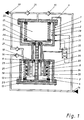
- the pump has a suction line 14 for the medium to be conveyed, which is connected to an upper interior 17 and a lower exterior 18 via an automatic check valve 15, 16 in each case.
- the pump has a pressure line 19 for the medium to be conveyed, which is also connected to the upper interior 17 and the lower exterior 18 via an automatic check valve 20, 21.
- the bellows 7, 8 are fastened to the end walls 9, 10 via flanges 22, 23 and to the bottoms 11, 12 by means of flanges 24, 25 by screws. If steel bellows are used, the flanges 24, 25 will usually be replaced by a welded construction.
- the piston rod 13 which is only subjected to tensile forces resulting from the suction force of the pump, is correspondingly light in construction and has two piston rod guides 26,27 and each sealed by one of the seals 5,6 between the upper outer space 2 and the lower inner space 4.
- control elements 28, 29 thus prevent the bellows 7,8 from moving beyond the permissible stroke and thus also impermissibly high differential pressures between the interior spaces 4.17 and the exterior spaces 2.18 of the bellows 7.8 at the stroke end points.
- the control elements 28, 29 serve to reverse the direction of movement and thus to interchange the suction and pressure functions of the two bellows 7, 8.
- the bellows 8 in the lower cylinder chamber 3 is subjected to internal pressure. It is guided over three slotted support rings 33, 34, 35, each of which is placed radially on the inside of a fold of the bellows 8, on a guide element 36 which is arranged concentrically with the bellows 8 and is fastened to the end wall 10 of the lower cylinder chamber 3 .
- the guide element 36 consists of a cylinder tube with four slits, which prevents the pressure medium from building up between the support rings.
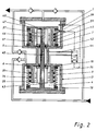
- FIG. 2 shows a pump in which an interior space 4.37 in each of the two cylinder spaces 1.3 directly adjoins the seals 5.6.
- This design is structurally somewhat more complex than the previous one, since both bellows 7, 8 are subjected to internal pressure and are therefore subject to a risk of kinking. To eliminate this danger, both bellows 7, 8 are equipped with the support rings 33, 34, 35, 38, 39, 40 and with the corresponding guide elements 36, 41, which are each fastened to the end wall 10, 42.
- a hollow-bored piston rod 43 is provided, since the pressure medium must be supplied to or removed from the bellows 7 arranged in the upper cylinder chamber 1 via the inlet and outlet 44 through the bores 45, 46, 47 in the piston rod 43 in order to be able to actuate it automatically To allow ventilation at the level of the bellows base 48.
Landscapes
- Engineering & Computer Science (AREA)
- Mechanical Engineering (AREA)
- General Engineering & Computer Science (AREA)
- Reciprocating Pumps (AREA)
Abstract
Claims (9)
- Une pompe à soufflets à double action pour les gaz et/ou les liquides, en particulier les milieux agressifs et/ou abrasifs, comportant deux chambres à cylindres (1,3) placées l'une au-dessus de l'autre partagées chacune par un soufflet (7,8) relié de manière hermétique et étanche à l'une de ses extrémités à une paroi frontale (9,10) de la chambre à cylindre concernée (1,3), et fermé par un fond (11,12,48) à son autre extrémité, en une chambre extérieure (2,18) et une chambre intérieure (4,17) entourée par le soufflet concerné (7,8); les fonds des soufflets (11,12,48) sont reliés mécaniquement l'un à l'autre par une tige de piston (13,43) passant à travers au moins un joint (5,6) de chaque chambre de cylindre (1,3), de manière qu'un soufflet (7) aspire pendant que l'autre (8) refoule; les chambres raccordées au joint ou aux joints (5,6) sont reliées par des conduites d'amenée et d'évacuation (31,32,44) pour un fluide de pressurisation et que les chambres raccordées au joint ou aux joints (5,6) sont reliées par des conduites d'amenée et d'évacuation (14,19) pour le médium à refouler, caractérisée en ce que dans chaque chambre des cylindres (1,3), une chambre interne (4,37) ou dans la chambre de cylindre inférieure (3) une chambre interne (4) et dans la chambre de cylindre supérieure (1) une chambre externe (2) se raccorde ou se raccordent directement au joint ou aux joints (5,6) et que les soufflets (7,8) de cette chambre interne (4,37) ou ces chambres internes raccordées directement au joint ou aux joints (5,6) butent chaque fois dans cette chambre interne (4,37) ou dans ces chambres internes au moins sur un élément de guidage (36,41) placé de manière concentrique sur chaque soufflet (7,8), élément de guidage qui est fixé chaque fois à la paroi avant (10,42) de la chambre de cylindre (1,3) concernée.
- Pompe selon la revendication 1, caractérisée en ce que le soufflet (7,8) repose au moyen d'au moins une bague d'appui (33,34,35,38,39,40) sur au moins un élément de guidage (36,41).
- Pompe selon les revendications 1 ou 2 caractérisée en ce que la bague d'appui (33,34,35,38,39,40) est fendue et fixée de manière auto-tendue sur au moins un pli du soufflet concerné (7,8) et que l'élément de guidage (36,41) est constitué d'un tube cylindrique qui est fendu ou perforé au moins une fois sur sa longueur.
- Pompe selon l'une des revendications ci-avant, caractérisée en ce que l'amenée et l'évacuation (44) du fluide de pressurisation de la chambre interne (37) se trouvant dans la chambre de cylindre supérieure (1) soient effectuées à l'aide d'un piston à tige creuse (43), de sorte que la liaison soit effectuée par la tige de piston creuse (43) vers la chambre intérieure (37) au moyen d'une perforation axiale (46) et par des perforations radiales (47) à la position la plus élevée de la chambre interne (37) ainsi que par des perforations radiales (45) entre les deux joints (5,6).
- Pompe selon l'un des revendications ci-avant, caractérisée en ce que les soufflets (7,8) sont constitués d'au moins deux parois de séparation placées l'une sur l'autre.
- Pompe selon la revendication 5, caractérisée en ce que la chambre intermédiaire ou les chambres intermédiaires entre les parois de séparation soit reliée ou soient reliées avec l'environnement à l'extérieur des chambres de cylindre (1,3), de sorte que la chambre intermédiaire ou les chambres intermédiaires serve ou servent de dérivation d'indication de fuite en cas de défaillance du soufflet.
- Pompe selon la revendication 5, caractérisée en ce qu'un film liquide inerte se trouve entre les parois de séparation des soufflets, film liquide qui donnerait une indication de fuite en cas de défaillance du soufflet
- Pompe selon l'une des revendications ci-avant, caractérisée en ce qu'il est prévu à la sortie de la pompe un réservoir hydraulique amortissant les pulsations présentes dans le flux de refoulement.
- Pompe selon la revendication 8, caractérisée en ce que le réservoir hydraulique est composé d'un soufflet se trouvant dans une chambre de cylindre, qui à une de ses extrémités est relié de manière hermétique à une paroi avant de la chambre du cylindre et qui à son autre extrémité est fermé par un fond, et de sorte que la chambre du cylindre est divisée en une chambre interne entourée par le soufflet, et une chambre externe, de sorte que la chambre interne ou externe est remplie d'un gaz inerte et la chambre externe ou interne du produit à refouler.
Priority Applications (1)
| Application Number | Priority Date | Filing Date | Title |
|---|---|---|---|
| AT89910823T ATE80703T1 (de) | 1988-10-06 | 1989-10-05 | Doppeltwirkende faltenbalgpumpe. |
Applications Claiming Priority (2)
| Application Number | Priority Date | Filing Date | Title |
|---|---|---|---|
| DE3833973 | 1988-10-06 | ||
| DE3833973 | 1988-10-06 |
Publications (2)
| Publication Number | Publication Date |
|---|---|
| EP0438428A1 EP0438428A1 (fr) | 1991-07-31 |
| EP0438428B1 true EP0438428B1 (fr) | 1992-09-16 |
Family
ID=6364488
Family Applications (1)
| Application Number | Title | Priority Date | Filing Date |
|---|---|---|---|
| EP89910823A Expired - Lifetime EP0438428B1 (fr) | 1988-10-06 | 1989-10-05 | Pompe a soufflet a double action |
Country Status (5)
| Country | Link |
|---|---|
| US (1) | US5141412A (fr) |
| EP (1) | EP0438428B1 (fr) |
| JP (1) | JPH04501158A (fr) |
| DE (1) | DE58902307D1 (fr) |
| WO (1) | WO1990004106A1 (fr) |
Families Citing this family (38)
| Publication number | Priority date | Publication date | Assignee | Title |
|---|---|---|---|---|
| US5224841A (en) * | 1992-04-24 | 1993-07-06 | Semitool, Inc. | Pneumatic bellows pump with supported bellows tube |
| US5308230A (en) * | 1993-03-08 | 1994-05-03 | Stainless Steel Products, Inc. | Bellows pump |
| US5480292A (en) * | 1993-05-19 | 1996-01-02 | Asti Sae | Dual chamber pump |
| US5381675A (en) * | 1993-09-07 | 1995-01-17 | Siegel; Israel | Force-sparing balanced bellows refrigeration device |
| US5375430A (en) * | 1993-10-05 | 1994-12-27 | Siegel; Israel | Gravity powered shoe air conditioner |
| US6446909B1 (en) * | 1997-04-18 | 2002-09-10 | Robert C. Michelson | Reciprocating chemical muscle(RCM) and method for using same |
| WO1999037921A1 (fr) * | 1998-01-26 | 1999-07-29 | Massachusetts Institute Of Technology | Pompe a soufflets a actionneur contractile |
| AUPP546598A0 (en) * | 1998-08-26 | 1998-09-17 | Bamford, John O. W. | Flexible cell assembly |
| US6241487B1 (en) | 1998-11-10 | 2001-06-05 | Warren Rupp, Inc. | Fluid powered diaphragm pump |
| US6021849A (en) | 1998-11-30 | 2000-02-08 | Averhoff; Jon R. | Double acting gas displaced chamber lift system and method |
| US6269884B1 (en) | 1998-11-30 | 2001-08-07 | Valence Operating Company | Gas displaced chamber lift system with closed loop/multi-stage vents |
| US6354377B1 (en) | 1998-11-30 | 2002-03-12 | Valence Operating Company | Gas displaced chamber lift system having gas lift assist |
| RU2167339C2 (ru) * | 1999-07-30 | 2001-05-20 | Самарский государственный аэрокосмический университет им. акад. С.П. Королева | Сильфонный компрессор с гидроприводом |
| JP3577435B2 (ja) * | 1999-11-29 | 2004-10-13 | 日本ピラー工業株式会社 | ベローズを有する流体機器 |
| JP3989334B2 (ja) * | 2002-08-23 | 2007-10-10 | 株式会社イワキ | 2連往復動ベローズポンプ |
| RU2237823C1 (ru) * | 2003-08-01 | 2004-10-10 | Мордовский государственный университет им. Н.П. Огарёва | Насос |
| US20050155658A1 (en) * | 2004-01-20 | 2005-07-21 | White Andrew J. | Hermetically sealed pressure balanced accumulator |
| EP1602830A1 (fr) * | 2004-06-02 | 2005-12-07 | Ailand Corporation S.A. | Pompe à piston avec plusieurs cylindres à propulsion hydraulique |
| US11078897B2 (en) * | 2008-06-27 | 2021-08-03 | Lynntech, Inc. | Apparatus for pumping fluid |
| US9518577B2 (en) * | 2008-06-27 | 2016-12-13 | Lynntech, Inc. | Apparatus for pumping a fluid |
| US20100178182A1 (en) * | 2009-01-09 | 2010-07-15 | Simmons Tom M | Helical bellows, pump including same and method of bellows fabrication |
| US8636484B2 (en) * | 2009-01-09 | 2014-01-28 | Tom M. Simmons | Bellows plungers having one or more helically extending features, pumps including such bellows plungers, and related methods |
| EP2622223A2 (fr) * | 2010-09-29 | 2013-08-07 | Dattatraya Rajaram Shelke | Dispositif pour transfert d'énergie entre deux fluides |
| CN102032154A (zh) * | 2010-11-25 | 2011-04-27 | 河源正信硬质合金有限公司 | 容积式液体输送器 |
| JP5720888B2 (ja) * | 2011-03-30 | 2015-05-20 | 株式会社イワキ | ベローズポンプ |
| US9261087B2 (en) | 2012-08-29 | 2016-02-16 | Linc Energy Systems, Inc. | Chemical injection system |
| CA2906850A1 (fr) * | 2013-03-15 | 2014-09-18 | Engineered Corrosion Solutions, Llc | Ensembles pompes et procedes pour empecher d'oxygene d'entrer dans des systemes d'alimentation en eau |
| DE102013213575A1 (de) | 2013-07-11 | 2015-01-15 | Mahle International Gmbh | Wärmerückgewinnungssystem für einen Verbrennungsmotor |
| KR101885017B1 (ko) * | 2014-07-10 | 2018-08-02 | 이글 고오교 가부시키가이샤 | 액체 공급 시스템 |
| EP3199812B1 (fr) * | 2014-09-22 | 2019-06-19 | Eagle Industry Co., Ltd. | Système d'alimentation en liquide |
| TW201727120A (zh) * | 2015-12-18 | 2017-08-01 | 葛萊兒明尼蘇達股份有限公司 | 波紋管內部軸承 |
| US10982665B2 (en) | 2015-12-18 | 2021-04-20 | Graco Minnesota Inc. | Bellows pressure relief valve |
| US10890172B2 (en) * | 2018-06-18 | 2021-01-12 | White Knight Fluid Handling Inc. | Fluid pumps and related systems and methods |
| RU2685353C1 (ru) * | 2018-10-02 | 2019-04-18 | Общество с ограниченной ответственностью "ТОРЕГ" | Насосная установка |
| KR20210001266A (ko) * | 2019-06-27 | 2021-01-06 | 김병식 | 에너지 변환 장치 |
| AU2022224818B1 (en) * | 2022-03-30 | 2023-02-02 | Idea Invent Evolve Pty Ltd | Energy storage device with a variable volume chamber |
| US12392336B2 (en) * | 2023-03-15 | 2025-08-19 | Westinghouse Electric Company Llc | Bellows pump for liquid metals |
| DE102024000719A1 (de) * | 2024-03-04 | 2025-09-04 | Hydac Technology Gmbh | Fördervorrichtung |
Family Cites Families (11)
| Publication number | Priority date | Publication date | Assignee | Title |
|---|---|---|---|---|
| US1546706A (en) * | 1925-07-21 | Guide fob corrugated waxls | ||
| US1920014A (en) * | 1931-06-26 | 1933-07-25 | Trico Products Corp | Multiple diaphragm pump |
| US2945376A (en) * | 1953-01-02 | 1960-07-19 | Gehre Hans | Pressure measuring device |
| US3092821A (en) * | 1960-09-06 | 1963-06-04 | Gen Dynamics Corp | Leak meter for detecting fluid pressure leaks |
| FR1328970A (fr) * | 1962-04-21 | 1963-06-07 | Commissariat Energie Atomique | Pompe doseuse |
| US3791768A (en) * | 1972-06-16 | 1974-02-12 | W Wanner | Fluid pump |
| US4008984A (en) * | 1975-10-23 | 1977-02-22 | Scholle William R | Pump apparatus |
| JPS6010189B2 (ja) * | 1979-01-19 | 1985-03-15 | アイシン精機株式会社 | ダイヤフラム式エアポンプ装置 |
| JPS60261651A (ja) * | 1984-06-07 | 1985-12-24 | Sumitomo Metal Ind Ltd | 連続鋳造方法 |
| JPS612790A (ja) * | 1984-06-16 | 1986-01-08 | Toa Nenryo Kogyo Kk | 原油の脱塩方法 |
| JPH067891B2 (ja) * | 1987-12-04 | 1994-02-02 | 倉敷紡績株式会社 | 循環▲ろ▼過システムのモニタ装置 |
-
1989
- 1989-10-05 EP EP89910823A patent/EP0438428B1/fr not_active Expired - Lifetime
- 1989-10-05 US US07/671,855 patent/US5141412A/en not_active Expired - Lifetime
- 1989-10-05 JP JP1510195A patent/JPH04501158A/ja active Pending
- 1989-10-05 WO PCT/DE1989/000636 patent/WO1990004106A1/fr not_active Ceased
- 1989-10-05 DE DE8989910823T patent/DE58902307D1/de not_active Expired - Lifetime
Also Published As
| Publication number | Publication date |
|---|---|
| DE58902307D1 (de) | 1992-10-22 |
| US5141412A (en) | 1992-08-25 |
| JPH04501158A (ja) | 1992-02-27 |
| WO1990004106A1 (fr) | 1990-04-19 |
| EP0438428A1 (fr) | 1991-07-31 |
Similar Documents
| Publication | Publication Date | Title |
|---|---|---|
| EP0438428B1 (fr) | Pompe a soufflet a double action | |
| DE3931516C2 (de) | Membranpumpe mit mechanisch angetriebener Membran | |
| DE1800018C3 (de) | Hydraulische Membranpumpe | |
| DE3441054C2 (fr) | ||
| DE69611780T2 (de) | Pumpe mit doppeltem effekt | |
| DE2355191C3 (de) | Kolbenpumpe | |
| DE4439962A1 (de) | Dosierpumpe mit Entlüftungseinrichtung | |
| DE7303301U (de) | Membran-Kolbenpumpe | |
| DE4327969A1 (de) | Hydraulisch angetriebene Membranpumpe | |
| DE3040478C2 (de) | Pumpe od.dgl. hydraulische Arbeitsmaschine | |
| DE4327970C2 (de) | Hydraulisch angetriebene Membranpumpe mit mechanischer Membranhubbegrenzung | |
| DE3334638A1 (de) | Vorrichtung zum anzeigen des bruchs einer membran | |
| DE3428629C2 (fr) | ||
| DE3507011A1 (de) | Fluessigkeitstransporteinrichtung vorzugsweise fuer farbstoffe und chemikalien | |
| DE1937161A1 (de) | Schlauchpumpe | |
| DE102017117983A1 (de) | Pumpen-Einheit, damit ausgestattete Lagervorrichtung sowie Verfahren zum Betreiben der Lagervorrichtung | |
| DE3210240A1 (de) | Membran-verdraengerpumpe | |
| DE3710013A1 (de) | Membranverdraengerpumpe, insbesondere fuer reibende, korrosive fluessigkeiten mit in suspension befindlichen teilchen od. dgl. | |
| DE3121103C2 (de) | Membranpumpe | |
| DD301225A7 (de) | Membranpumpe | |
| DE19903052B4 (de) | Membrankolbenpumpe | |
| DE1450347C (de) | Zweiteiliger Trennkolben zur gegen seitigen Abdichtung benachbarter Druckraume eines Zylinders eines Kolben druckspeicher | |
| DE962498C (de) | Membranpumpe | |
| DE2701171A1 (de) | Peristaltische membranpumpe zur foerderung von schlaemmen und dickstoffen, mit pneumatisch-hydraulischem antrieb | |
| DE1198626B (de) | Durch eine Rollmembran hergestellte Abdichtung zwischen einem Zylinder bzw. einem Gehaeuse und einem bzw. einer darin bewegbaren Kolben oder Stange |
Legal Events
| Date | Code | Title | Description |
|---|---|---|---|
| PUAI | Public reference made under article 153(3) epc to a published international application that has entered the european phase |
Free format text: ORIGINAL CODE: 0009012 |
|
| 17P | Request for examination filed |
Effective date: 19910323 |
|
| AK | Designated contracting states |
Kind code of ref document: A1 Designated state(s): AT BE CH DE FR GB IT LI LU NL SE |
|
| 17Q | First examination report despatched |
Effective date: 19920205 |
|
| GRAA | (expected) grant |
Free format text: ORIGINAL CODE: 0009210 |
|
| AK | Designated contracting states |
Kind code of ref document: B1 Designated state(s): AT BE CH DE FR GB IT LI LU NL SE |
|
| REF | Corresponds to: |
Ref document number: 80703 Country of ref document: AT Date of ref document: 19921015 Kind code of ref document: T |
|
| REF | Corresponds to: |
Ref document number: 58902307 Country of ref document: DE Date of ref document: 19921022 |
|
| PGFP | Annual fee paid to national office [announced via postgrant information from national office to epo] |
Ref country code: NL Payment date: 19921031 Year of fee payment: 4 |
|
| PGFP | Annual fee paid to national office [announced via postgrant information from national office to epo] |
Ref country code: LU Payment date: 19921104 Year of fee payment: 4 |
|
| ITF | It: translation for a ep patent filed | ||
| GBT | Gb: translation of ep patent filed (gb section 77(6)(a)/1977) | ||
| ET | Fr: translation filed | ||
| EPTA | Lu: last paid annual fee | ||
| PLBE | No opposition filed within time limit |
Free format text: ORIGINAL CODE: 0009261 |
|
| STAA | Information on the status of an ep patent application or granted ep patent |
Free format text: STATUS: NO OPPOSITION FILED WITHIN TIME LIMIT |
|
| 26N | No opposition filed | ||
| PG25 | Lapsed in a contracting state [announced via postgrant information from national office to epo] |
Ref country code: LU Free format text: LAPSE BECAUSE OF NON-PAYMENT OF DUE FEES Effective date: 19931005 |
|
| PG25 | Lapsed in a contracting state [announced via postgrant information from national office to epo] |
Ref country code: NL Effective date: 19940501 |
|
| NLV4 | Nl: lapsed or anulled due to non-payment of the annual fee | ||
| PGFP | Annual fee paid to national office [announced via postgrant information from national office to epo] |
Ref country code: SE Payment date: 19940927 Year of fee payment: 6 |
|
| PGFP | Annual fee paid to national office [announced via postgrant information from national office to epo] |
Ref country code: AT Payment date: 19940929 Year of fee payment: 6 |
|
| REG | Reference to a national code |
Ref country code: CH Ref legal event code: PUE Owner name: REGIPUR POLYURETHAN-ANLAGEN-TECHNIK GMBH |
|
| EAL | Se: european patent in force in sweden |
Ref document number: 89910823.7 |
|
| REG | Reference to a national code |
Ref country code: GB Ref legal event code: 732E |
|
| REG | Reference to a national code |
Ref country code: FR Ref legal event code: TP |
|
| PG25 | Lapsed in a contracting state [announced via postgrant information from national office to epo] |
Ref country code: AT Effective date: 19951005 |
|
| PG25 | Lapsed in a contracting state [announced via postgrant information from national office to epo] |
Ref country code: SE Effective date: 19951006 |
|
| EUG | Se: european patent has lapsed |
Ref document number: 89910823.7 |
|
| PGFP | Annual fee paid to national office [announced via postgrant information from national office to epo] |
Ref country code: CH Payment date: 19980918 Year of fee payment: 10 |
|
| PGFP | Annual fee paid to national office [announced via postgrant information from national office to epo] |
Ref country code: FR Payment date: 19980925 Year of fee payment: 10 |
|
| PGFP | Annual fee paid to national office [announced via postgrant information from national office to epo] |
Ref country code: GB Payment date: 19981009 Year of fee payment: 10 |
|
| PG25 | Lapsed in a contracting state [announced via postgrant information from national office to epo] |
Ref country code: GB Free format text: LAPSE BECAUSE OF NON-PAYMENT OF DUE FEES Effective date: 19991005 |
|
| PG25 | Lapsed in a contracting state [announced via postgrant information from national office to epo] |
Ref country code: LI Free format text: LAPSE BECAUSE OF NON-PAYMENT OF DUE FEES Effective date: 19991031 Ref country code: CH Free format text: LAPSE BECAUSE OF NON-PAYMENT OF DUE FEES Effective date: 19991031 |
|
| GBPC | Gb: european patent ceased through non-payment of renewal fee |
Effective date: 19991005 |
|
| REG | Reference to a national code |
Ref country code: CH Ref legal event code: PL |
|
| PG25 | Lapsed in a contracting state [announced via postgrant information from national office to epo] |
Ref country code: FR Free format text: LAPSE BECAUSE OF NON-PAYMENT OF DUE FEES Effective date: 20000630 |
|
| REG | Reference to a national code |
Ref country code: FR Ref legal event code: ST |
|
| PGFP | Annual fee paid to national office [announced via postgrant information from national office to epo] |
Ref country code: BE Payment date: 20001025 Year of fee payment: 12 |
|
| PGFP | Annual fee paid to national office [announced via postgrant information from national office to epo] |
Ref country code: DE Payment date: 20001116 Year of fee payment: 12 |
|
| PG25 | Lapsed in a contracting state [announced via postgrant information from national office to epo] |
Ref country code: BE Free format text: LAPSE BECAUSE OF NON-PAYMENT OF DUE FEES Effective date: 20011031 |
|
| BERE | Be: lapsed |
Owner name: REGIPUR POLYURETHAN-ANLAGEN-TECHNIK G.M.B.H. Effective date: 20011031 |
|
| PG25 | Lapsed in a contracting state [announced via postgrant information from national office to epo] |
Ref country code: DE Free format text: LAPSE BECAUSE OF NON-PAYMENT OF DUE FEES Effective date: 20020702 |
|
| PG25 | Lapsed in a contracting state [announced via postgrant information from national office to epo] |
Ref country code: IT Free format text: LAPSE BECAUSE OF NON-PAYMENT OF DUE FEES;WARNING: LAPSES OF ITALIAN PATENTS WITH EFFECTIVE DATE BEFORE 2007 MAY HAVE OCCURRED AT ANY TIME BEFORE 2007. THE CORRECT EFFECTIVE DATE MAY BE DIFFERENT FROM THE ONE RECORDED. Effective date: 20051005 |