EP0438440B1 - Limiteur de flexion pour cable a fibres optiques - Google Patents
Limiteur de flexion pour cable a fibres optiques Download PDFInfo
- Publication number
- EP0438440B1 EP0438440B1 EP89911060A EP89911060A EP0438440B1 EP 0438440 B1 EP0438440 B1 EP 0438440B1 EP 89911060 A EP89911060 A EP 89911060A EP 89911060 A EP89911060 A EP 89911060A EP 0438440 B1 EP0438440 B1 EP 0438440B1
- Authority
- EP
- European Patent Office
- Prior art keywords
- sleeve
- bend restrictor
- cable
- bore
- optical fibre
- Prior art date
- Legal status (The legal status is an assumption and is not a legal conclusion. Google has not performed a legal analysis and makes no representation as to the accuracy of the status listed.)
- Expired - Lifetime
Links
Images

Classifications
-
- G—PHYSICS
- G02—OPTICS
- G02B—OPTICAL ELEMENTS, SYSTEMS OR APPARATUS
- G02B6/00—Light guides; Structural details of arrangements comprising light guides and other optical elements, e.g. couplings
- G02B6/24—Coupling light guides
- G02B6/255—Splicing of light guides, e.g. by fusion or bonding
- G02B6/2558—Reinforcement of splice joint
-
- G—PHYSICS
- G02—OPTICS
- G02B—OPTICAL ELEMENTS, SYSTEMS OR APPARATUS
- G02B6/00—Light guides; Structural details of arrangements comprising light guides and other optical elements, e.g. couplings
- G02B6/44—Mechanical structures for providing tensile strength and external protection for fibres, e.g. optical transmission cables
- G02B6/4401—Optical cables
- G02B6/4429—Means specially adapted for strengthening or protecting the cables
- G02B6/443—Protective covering
-
- G—PHYSICS
- G02—OPTICS
- G02B—OPTICAL ELEMENTS, SYSTEMS OR APPARATUS
- G02B6/00—Light guides; Structural details of arrangements comprising light guides and other optical elements, e.g. couplings
- G02B6/44—Mechanical structures for providing tensile strength and external protection for fibres, e.g. optical transmission cables
- G02B6/4439—Auxiliary devices
Definitions
- This invention relates to a bend restrictor for optical fibre cable, and in particular to a bend restrictor for preventing a submarine optical fibre cable bending too much at a joint.
- a submarine optical fibre cable has a plurality of optical fibres at its centre, the optical fibres being surrounded by a copper tube, which in turn is surrounded by two layers of helically-wound steel wires which are encapsulated in plastics material.
- the steel wires carry longitudinal cable forces, and the copper tube carries electrical power to components such as repeaters spaced along the cable.
- the optical fibres are subject to a bend restriction, namely that they should not bend with a radius of curvature of less than about one metre, and so the cable itself is also limited in this way. This gives rise to problems at cable joints (a cable joint is a connection from cable to cable) and at termination joints (a termination joint connects a cable to a repeater, via what is known as a pig-tail).
- a cable joint has a steel sleeve surrounding the joint, and the cables leaving this sleeve tend to bend sharply when subject to transverse forces, particularly as the cable is being laid or recovered around the forward or aft sheaves of a cable ship or around a cable engine drum. Similar problems arise with termination joints.
- a known bend limiter is constituted by a boot made of artificial rubber.
- the boot is a tapered sleeve-like member, which is about one metre in length, the boot having a steel coupling ring moulded into its wider end.
- the coupling ring is externally threaded for connection to the steel sleeve of a cable joint.
- the wider end of the boot is about 5 to 6 inches (127 to 152 mm) in diameter, and the bore of the boot is about 1.5 inches (38 mm), the dimensions being chosen to take standard commercial cables of diameter between 1 and 1.25 inches (25 and 31 mm).
- the known type of boot tapers so that the boot has a varying rigidity along its length.
- the conical shape of the boot also acts as a smooth contour profile to allow the diameter discontinuity of the cable-to-joint interface to pass through or around ship's machinery with much reduced risk of fouling.
- the boot rigidity is arranged to vary from a very high value at its wider end (to match the rigidity of the steel sleeve of the cable joint) to a relatively low value at its narrower end (to match the rigidity of the cable).
- a bend restrictor of this type is known from British Telecommunications Engineering, vol.5, no.2, pages 104-108, C. A. Gould, "Cable-to-repeater connection and repeater mechanical design for submarine optical-fibre cable systems.
- the present invention provides a bend restrictor for an optical fibre cable, the bend restrictor comprising an elongated sleeve-like member having an axial through bore for accommodating the cable, and a coupling ring for fixing the sleeve-like member to a rigid housing from which the cable extends, wherein the sleeve-like member is provided with a plurality of longitudinal bores, and wherein at least one of the bores is provided with a stiffening rod.
- the sleeve-like member is made of a plastics material such as a cast polyurethane rubber, preferably a two-component, ambient temperature curing polyurethane elastomer having a Shore A Hardness, after 7 days' curing, of at least 72.
- the sleeve-like member has a length of substantially 1 m, the axial through bore of the sleeve-like member having a diameter of substantially 1.5 inches (38 mm), and the sleeve-like member tapering away from the coupling ring end thereof.
- the maximum external diameter of the sleeve-like member may lie within the range of from 4 to 8 inches (100 mm to 200 mm), and preferably is substantially 6 inches (150 mm).
- the narrow, free end portion of the sleeve-like member may be subdivided into a plurality of axially-extending finger portions, each of which is formed with a longitudinal aperture which forms part of a respective longitudinal bore.
- the bend restrictor may further comprise clamping means for clamping the finger portions firmly to an optical fibre cable accommodated within the axial through bore.
- each of the longitudinal bores has a diameter of 10mm.
- Each of the stiffening rods may be made of pultruded glass fibre having a 50-75% glass fibre content within an embedding resin matrix.
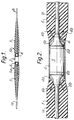
- Figure 1 shows two sections 1a and 1b of an optical fibre cable, these sections being connected together by a cable joint assembly, indicated generally by the reference numeral 2.
- the cable joint assembly 2 includes a moulded cable joint 3 of standard construction, the joint being surrounded by a protective steel sleeve 4.
- the portions of the cable sections 1a and 1b adjacent to the cable joint assembly 2 are each provided with a bend restrictor (universal boot) 5 constructed in accordance with the invention.
- the boots 5 are made of an artificial rubber (such as EMC 70B, which is a two-component, ambient temperature curing polyurethane system which yields a tough elastomer having a Shore A Hardness, after 7 days' curing, of about 72), and have a length of about 1 m.
- EMC 70B which is a two-component, ambient temperature curing polyurethane system which yields a tough elastomer having a Shore A Hardness, after 7 days' curing, of about 72
- Each boot 5 has an internal diameter of 1.5 inches (38 mm), and has an external diameter which tapers from 6 inches (150 mm), at the end thereof adjacent to the cable joint assembly 2, to about 1.75 inches (45 mm) at the opposite end.
- Each boot 5 is fixed to the sleeve 4 by means of a respective coupling ring 6.
- Each coupling ring 6 has a generally cylindrical, externally-threaded portion 4a which is threadably engageable with an internally-threaded end portion 4a of the sleeve 4.
- the coupling rings 6 are generally crown-shaped, having prongs 6b which are moulded into the wider end portions 5a of the boots 5.
- each boot 5 is formed with six equispaced, symmetrically-positioned, longitudinal bores 7, whose mouths 7a lie on the annular end face of the boot adjacent to the associated coupling ring 6.
- these bores 7 are occupied by stiffening rods 8 made of pultruded glass fibre having 50-75% glass fibre within an embedding resin matrix.
- the bores 7 have a diameter of 10mm and a length of 80mm, and the rods 8 can have various lengths up to this length.
- the rigidity of the boots 5 can be varied to suit the rigidity of any type of optical fibre cable.
- the boot 5 can be used with all standard commercial optical fibre cables. Where the outer diameter of such a cable is significantly less than the 1.5 inch (38 mm) internal bore of the boot 5, the clearance between the two can be reduced by wrapping suitable material round the cable within the bore of the boot. In this way, cables down to an outer diameter of 0.75 inch (19 mm) can be accommodated. For cables having a smaller diameter than this (for example, specialised or military cables), a boot having an internal bore of 0.75 inch (19 mm) would be preferable. Such small diameter cables are, however, extremely specialised and rare, and so their existence does not materially affect the universality of application of the boot of the invention.
- Fig. 5 shows the narrow end portion 15a of a modified form of boot 15.
- the narrow end portion 15a is subdivided to form six equispaced axially-extending fingers 15b, each of which is formed with a longitudinal bore which forms part of a respective bore 17 in the main body of the boot 15.
- a pair of axially-spaced retaining clips 29 are provided for clamping the fingers 15b (and hence any stiffening rods 18 positioned therein) firmly to the associated optical fibre cable 11.
- the portion 15a of the boot 15 is clamped firmly to the cable 11, the cable is protected from excessive torsional forces.
- the arrangement of the fingers 15b and the clips 29 is such that the boot portion 15a can be clamped to cables 11 of different diameters.
- the modified boot 15 can also be used with all standard commercial optical fibre cables.
Landscapes
- Physics & Mathematics (AREA)
- General Physics & Mathematics (AREA)
- Optics & Photonics (AREA)
- Engineering & Computer Science (AREA)
- Plasma & Fusion (AREA)
- Light Guides In General And Applications Therefor (AREA)
- Mechanical Coupling Of Light Guides (AREA)
- Cable Accessories (AREA)
Abstract
Claims (11)
- Un limiteur de flexion pour un câble (1a, 1b) à fibres optiques, le limiteur de flexion comprenant un organe allongé (5) en forme de manchon dans lequel est ménagé un alésage axial traversant pour loger le câble, et une bague d'accouplement (6) disposée à une extrémité de l'élément (5) en forme de manchon afin de fixer l'élément (5) en forme de manchon à un boîtier rigide (3) à partir duquel s'étend le câble, caractérisé en ce que plusieurs alésages longitudinaux sont ménagés dans l'élément (5) en forme de manchon et en ce qu'au moins l'un des alésages comprend une tige de renforcement (8).
- Un limiteur de flexion selon la revendication 1, dans lequel l'élément (5) en forme de manchon est en matière plastique.
- Un limiteur de flexion selon la revendication 2, dans lequel la matière plastique est un caoutchouc de polyuréthanne coulé.
- Un limiteur de flexion selon la revendication 3, dans lequel le caoutchouc de polyuréthanne coulé est un élastomère de polyuréthanne à deux composants, à traiter à la température amoiante, dont la dureté Shore A est d'environ 72 après un traitement de 7 jours.
- Un limiteur de flexion selon l'une quelconque des revendications 1 à 4, dans lequel la longueur de l'élément (5) en forme de manchon est sensiblement de 1 m, le diamètre de l'alésage axial traversant de l'élément en forme de manchon est sensiblement de 38 mm (1,5 pouce) et l'élément en forme de manchon (5) s'effile à partir de son extrémité de bague (6) d'accouplement.
- Un limiteur de flexion selon la revendication 5, dans lequel le diamètre externe maximal de l'élément (5) en forme de manchon est situé dans la plage de 100 mm à 200 mm (4 à 8 pouces).
- Un limiteur de flexion selon la revendication 6, dans lequel le diamètre maximal extérieur de l'élément (5) en forme de manchon est sensiblement de 150 mm (6 pouces).
- Un limiteur de flexion selon l'une quelconque des revendications 5 à 7, dans laquelle la partie d'extrémité libre étroite (15a) de l'élément (5) en forme de manchon est subdivisée en une série de parties (15b) de doigts s'étendant axialement, chacune d'elles comprenant une ouverture longitudinale qui fait partie d'un alésage longitudinal respectif (17).
- Un limiteur de flexion selon la revendication 8, comprenant en outre un moyen de serrage (29) pour serrer fermement les parties (15b) de doigts sur un câble (1a, 1b) à fibres optiques logé à l'intérieur de l'alésage axial traversant.
- Un limiteur de flexion selon l'une quelconque des revendications 1 à 9, dans lequel le diamètre de chacun des alésages longitudinaux (7, 17) est de 10 mm.
- Un limiteur de flexion selon l'une quelconque des revendications 1 à 10, dans lequel chacune des tiges de raidissement (8) est un fibre de verre extrudée par étirage à teneur en fibre de verre de 50 à 75% à l'intérieur d'une matrice d'enrobage en résine.
Priority Applications (1)
| Application Number | Priority Date | Filing Date | Title |
|---|---|---|---|
| AT89911060T ATE104447T1 (de) | 1988-10-17 | 1989-10-04 | Begrenzungselement fuer die kruemmung eines optischen kabels. |
Applications Claiming Priority (3)
| Application Number | Priority Date | Filing Date | Title |
|---|---|---|---|
| GB888824246A GB8824246D0 (en) | 1988-10-17 | 1988-10-17 | Bend restrictor for optical fibre cable |
| GB8824246 | 1988-10-17 | ||
| PCT/GB1989/001175 WO1990004800A1 (fr) | 1988-10-17 | 1989-10-04 | Limiteur de flexion pour cable a fibres optiques |
Publications (2)
| Publication Number | Publication Date |
|---|---|
| EP0438440A1 EP0438440A1 (fr) | 1991-07-31 |
| EP0438440B1 true EP0438440B1 (fr) | 1994-04-13 |
Family
ID=10645299
Family Applications (1)
| Application Number | Title | Priority Date | Filing Date |
|---|---|---|---|
| EP89911060A Expired - Lifetime EP0438440B1 (fr) | 1988-10-17 | 1989-10-04 | Limiteur de flexion pour cable a fibres optiques |
Country Status (10)
| Country | Link |
|---|---|
| US (1) | US5081695A (fr) |
| EP (1) | EP0438440B1 (fr) |
| JP (1) | JPH06103364B2 (fr) |
| AU (1) | AU613539B2 (fr) |
| CA (1) | CA2000206C (fr) |
| DE (1) | DE68914681T2 (fr) |
| DK (1) | DK165891C (fr) |
| ES (1) | ES2016205A6 (fr) |
| GB (1) | GB8824246D0 (fr) |
| WO (1) | WO1990004800A1 (fr) |
Families Citing this family (11)
| Publication number | Priority date | Publication date | Assignee | Title |
|---|---|---|---|---|
| GB2256285B (en) * | 1991-06-01 | 1995-02-01 | Northern Telecom Ltd | Underwater cable joints |
| US5309538A (en) * | 1991-09-06 | 1994-05-03 | Minnesota Mining And Manufacturing Company | Reinforced multiple optical fiber splice having preanodized element |
| US5157751A (en) * | 1992-01-14 | 1992-10-20 | Litton Systems, Inc. | Fiber optic splice protector and method for making same |
| US5469522A (en) * | 1993-12-02 | 1995-11-21 | Litecom, Inc. | Optical fiber splice interconnection and usage method |
| US6454471B1 (en) | 1999-12-01 | 2002-09-24 | Amherst Holding Co. | Optical fiber splice sleeve and method for applying same |
| US6499891B1 (en) | 2001-08-30 | 2002-12-31 | The United States Of America As Represented By The Secretary Of The Navy | Rapid cable-splice for high-tensile applications |
| US20030185522A1 (en) * | 2002-04-02 | 2003-10-02 | Young Craig A. | Bend limiter |
| US10799209B2 (en) | 2012-12-26 | 2020-10-13 | Philips Image Guided Therapy Corporation | Measurement navigation in a multi-modality medical imaging system |
| US10368836B2 (en) | 2012-12-26 | 2019-08-06 | Volcano Corporation | Gesture-based interface for a multi-modality medical imaging system |
| US10642953B2 (en) | 2012-12-26 | 2020-05-05 | Philips Image Guided Therapy Corporation | Data labeling and indexing in a multi-modality medical imaging system |
| US12510717B2 (en) * | 2023-03-23 | 2025-12-30 | Metrohm Spectro, Inc. | Dual-diameter jacketed fiber-coupled optoelectronic module |
Family Cites Families (16)
| Publication number | Priority date | Publication date | Assignee | Title |
|---|---|---|---|---|
| US3082291A (en) * | 1959-11-02 | 1963-03-19 | Clevite Corp | Hermetic seal |
| US3516830A (en) * | 1965-09-17 | 1970-06-23 | Eastman Kodak Co | Photographic silver halide emulsions and elements |
| US4259543A (en) * | 1978-02-07 | 1981-03-31 | International Telephone And Telegraph Corporation | Cable termination |
| US4245134A (en) * | 1978-09-11 | 1981-01-13 | International Standard Electric Corporation | Cable termination apparatus |
| GB2042816B (en) * | 1979-02-27 | 1983-02-23 | Standard Telephones Cables Ltd | Cable termination securement |
| DE3023669C2 (de) * | 1980-06-25 | 1983-01-20 | Philips Kommunikations Industrie AG, 8500 Nürnberg | Selbsttragendes optisches Nachrichtenkabel |
| GB2079485B (en) * | 1980-07-08 | 1984-07-25 | Standard Telephones Cables Ltd | Armoured wire splices |
| FR2505569A1 (fr) * | 1981-05-07 | 1982-11-12 | Cables De Lyon Geoffroy Delore | Jonction multiple pour systeme sous-marin |
| JPS59160103A (ja) * | 1983-03-04 | 1984-09-10 | Kokusai Denshin Denwa Co Ltd <Kdd> | 外装光海底ケ−ブルの引留め構造 |
| FR2547660B1 (fr) * | 1983-06-15 | 1985-09-27 | Cables De Lyon Geoffroy Delore | Jonction multiple pour cables sous-marins a fibres optiques |
| AU584891B2 (en) * | 1984-04-19 | 1989-06-08 | E.I. Du Pont De Nemours And Company | Optical fiber material having optical fiber tightly held by wrapping material |
| IT1176347B (it) * | 1984-06-29 | 1987-08-18 | Pirelli Cavi Spa | Giunto per cavi sottomarini di telecomunicazione a fibre ottiche |
| GB8426138D0 (en) * | 1984-10-16 | 1984-11-21 | British Telecomm | Bend limiter |
| US4790648A (en) * | 1986-08-12 | 1988-12-13 | The Furakawa Electric Co., Ltd. | Closure for cable connector |
| IT1202607B (it) * | 1987-03-02 | 1989-02-09 | Pirelli Cavi Spa | Giunto per cavi di telecomunicazione a fibre ottiche |
| AU589829B2 (en) * | 1988-01-21 | 1989-10-19 | American Telephone And Telegraph Company | High and low pressure fluidblock assembly |
-
1988
- 1988-10-17 GB GB888824246A patent/GB8824246D0/en active Pending
-
1989
- 1989-10-04 EP EP89911060A patent/EP0438440B1/fr not_active Expired - Lifetime
- 1989-10-04 JP JP1510323A patent/JPH06103364B2/ja not_active Expired - Lifetime
- 1989-10-04 US US07/671,815 patent/US5081695A/en not_active Expired - Lifetime
- 1989-10-04 DE DE68914681T patent/DE68914681T2/de not_active Expired - Lifetime
- 1989-10-04 WO PCT/GB1989/001175 patent/WO1990004800A1/fr not_active Ceased
- 1989-10-05 CA CA002000206A patent/CA2000206C/fr not_active Expired - Lifetime
- 1989-10-13 ES ES8903446A patent/ES2016205A6/es not_active Expired - Lifetime
- 1989-11-17 AU AU44776/89A patent/AU613539B2/en not_active Expired
-
1991
- 1991-04-12 DK DK066791A patent/DK165891C/da not_active IP Right Cessation
Also Published As
| Publication number | Publication date |
|---|---|
| AU4477689A (en) | 1991-05-23 |
| ES2016205A6 (es) | 1990-10-16 |
| DK165891B (da) | 1993-02-01 |
| GB8824246D0 (en) | 1988-11-23 |
| DK66791D0 (da) | 1991-04-12 |
| CA2000206C (fr) | 1997-05-06 |
| DE68914681D1 (de) | 1994-05-19 |
| DE68914681T2 (de) | 1994-07-28 |
| EP0438440A1 (fr) | 1991-07-31 |
| JPH04501179A (ja) | 1992-02-27 |
| JPH06103364B2 (ja) | 1994-12-14 |
| DK165891C (da) | 1993-06-28 |
| DK66791A (da) | 1991-04-12 |
| US5081695A (en) | 1992-01-14 |
| WO1990004800A1 (fr) | 1990-05-03 |
| AU613539B2 (en) | 1991-08-01 |
| CA2000206A1 (fr) | 1990-04-17 |
Similar Documents
| Publication | Publication Date | Title |
|---|---|---|
| EP0438440B1 (fr) | Limiteur de flexion pour cable a fibres optiques | |
| CA1194353A (fr) | Dispositif protecteur de fibres optiques a decouvert en bout d'un cable | |
| KR100295357B1 (ko) | 광섬유케이블 | |
| KR940002354B1 (ko) | 헤저 광섬유 케이블 선 | |
| JP2868828B2 (ja) | 光ファイバケーブル接合装置 | |
| EP0067673A2 (fr) | Couplage de câbles à fibres optiques | |
| DK0405851T3 (da) | Kabel, der har et ikke-metallisk armeringslag | |
| RU2072541C1 (ru) | Устройство захвата для оптического кабеля с волоконнооптическими лентами | |
| NZ209903A (en) | Overhead cable core carries optical fibres | |
| US20210325623A1 (en) | Fiber optic cable breakout assembly | |
| US11327231B2 (en) | Flexible splice protector assembly and method for preparing same | |
| US4699462A (en) | Fiber optic cable termination and method for forming same | |
| US4330173A (en) | Conductor for optical cables | |
| GB2242035A (en) | Restricting expansion of fibre optic sheath | |
| EP0153799A1 (fr) | Jonction protégé par un manchon pour câbles sous-marins | |
| US4644097A (en) | Armored submarine power cable | |
| US11360264B2 (en) | Telecommunications splice arrangements | |
| US4207428A (en) | Telecommunications submarine cable assemblies | |
| US20020012504A1 (en) | Angled fiber optic connector | |
| US5241618A (en) | Termination and joint for optical telecommunications cable | |
| US6101303A (en) | Junction configuration for a multi-conductor optical cable | |
| EP0465127A1 (fr) | Dispositif de rangement de fibres optiques | |
| US4704500A (en) | Apparatus for relieving a load across a cable repair region | |
| FI95091B (fi) | Painetiivis muhvi | |
| Furukawa et al. | Structural design and sea trial results for a submarine optical-fiber cable joint box |
Legal Events
| Date | Code | Title | Description |
|---|---|---|---|
| PUAI | Public reference made under article 153(3) epc to a published international application that has entered the european phase |
Free format text: ORIGINAL CODE: 0009012 |
|
| 17P | Request for examination filed |
Effective date: 19910319 |
|
| AK | Designated contracting states |
Kind code of ref document: A1 Designated state(s): AT BE CH DE FR GB IT LI LU NL SE |
|
| 17Q | First examination report despatched |
Effective date: 19930621 |
|
| GRAA | (expected) grant |
Free format text: ORIGINAL CODE: 0009210 |
|
| AK | Designated contracting states |
Kind code of ref document: B1 Designated state(s): AT BE CH DE FR GB IT LI LU NL SE |
|
| PG25 | Lapsed in a contracting state [announced via postgrant information from national office to epo] |
Ref country code: AT Effective date: 19940413 Ref country code: LI Effective date: 19940413 Ref country code: CH Effective date: 19940413 |
|
| REF | Corresponds to: |
Ref document number: 104447 Country of ref document: AT Date of ref document: 19940415 Kind code of ref document: T |
|
| ITF | It: translation for a ep patent filed | ||
| REF | Corresponds to: |
Ref document number: 68914681 Country of ref document: DE Date of ref document: 19940519 |
|
| REG | Reference to a national code |
Ref country code: CH Ref legal event code: PL |
|
| ET | Fr: translation filed | ||
| PG25 | Lapsed in a contracting state [announced via postgrant information from national office to epo] |
Ref country code: LU Free format text: LAPSE BECAUSE OF NON-PAYMENT OF DUE FEES Effective date: 19941031 |
|
| EAL | Se: european patent in force in sweden |
Ref document number: 89911060.5 |
|
| PLBE | No opposition filed within time limit |
Free format text: ORIGINAL CODE: 0009261 |
|
| STAA | Information on the status of an ep patent application or granted ep patent |
Free format text: STATUS: NO OPPOSITION FILED WITHIN TIME LIMIT |
|
| 26N | No opposition filed | ||
| NLS | Nl: assignments of ep-patents |
Owner name: CABLE & WIRELESS PLC |
|
| REG | Reference to a national code |
Ref country code: FR Ref legal event code: TP |
|
| REG | Reference to a national code |
Ref country code: GB Ref legal event code: 732E |
|
| REG | Reference to a national code |
Ref country code: GB Ref legal event code: 732E |
|
| BECA | Be: change of holder's address |
Free format text: 20000928 *GLOBAL MARINE SYSTEMS LTD:EAST SAXON HOUSE 27 DUKE STREET, CHELMSFORD ESSEX CM1 1HT |
|
| BECN | Be: change of holder's name |
Effective date: 20000928 |
|
| NLS | Nl: assignments of ep-patents |
Owner name: CABLE & WIRELESS MARINE LIMITED |
|
| NLT1 | Nl: modifications of names registered in virtue of documents presented to the patent office pursuant to art. 16 a, paragraph 1 |
Owner name: GLOBAL MARINE SYSTEMS LIMITED |
|
| REG | Reference to a national code |
Ref country code: FR Ref legal event code: TP Ref country code: FR Ref legal event code: CD |
|
| REG | Reference to a national code |
Ref country code: GB Ref legal event code: IF02 |
|
| PGFP | Annual fee paid to national office [announced via postgrant information from national office to epo] |
Ref country code: NL Payment date: 20081005 Year of fee payment: 20 |
|
| PGFP | Annual fee paid to national office [announced via postgrant information from national office to epo] |
Ref country code: DE Payment date: 20081014 Year of fee payment: 20 |
|
| PGFP | Annual fee paid to national office [announced via postgrant information from national office to epo] |
Ref country code: BE Payment date: 20081030 Year of fee payment: 20 Ref country code: IT Payment date: 20081028 Year of fee payment: 20 Ref country code: SE Payment date: 20081022 Year of fee payment: 20 |
|
| PGFP | Annual fee paid to national office [announced via postgrant information from national office to epo] |
Ref country code: FR Payment date: 20081014 Year of fee payment: 20 |
|
| PGFP | Annual fee paid to national office [announced via postgrant information from national office to epo] |
Ref country code: GB Payment date: 20081008 Year of fee payment: 20 |
|
| REG | Reference to a national code |
Ref country code: GB Ref legal event code: PE20 Expiry date: 20091003 |
|
| BE20 | Be: patent expired |
Owner name: *GLOBAL MARINE SYSTEMS LTD Effective date: 20091004 |
|
| NLV7 | Nl: ceased due to reaching the maximum lifetime of a patent | ||
| EUG | Se: european patent has lapsed | ||
| PG25 | Lapsed in a contracting state [announced via postgrant information from national office to epo] |
Ref country code: NL Free format text: LAPSE BECAUSE OF EXPIRATION OF PROTECTION Effective date: 20091004 |
|
| PG25 | Lapsed in a contracting state [announced via postgrant information from national office to epo] |
Ref country code: GB Free format text: LAPSE BECAUSE OF EXPIRATION OF PROTECTION Effective date: 20091003 |