EP0438549B1 - Construction de seuil pour un deversior basculant - Google Patents
Construction de seuil pour un deversior basculant Download PDFInfo
- Publication number
- EP0438549B1 EP0438549B1 EP90909778A EP90909778A EP0438549B1 EP 0438549 B1 EP0438549 B1 EP 0438549B1 EP 90909778 A EP90909778 A EP 90909778A EP 90909778 A EP90909778 A EP 90909778A EP 0438549 B1 EP0438549 B1 EP 0438549B1
- Authority
- EP
- European Patent Office
- Prior art keywords
- weir
- weir gate
- support plate
- lower edge
- gate
- Prior art date
- Legal status (The legal status is an assumption and is not a legal conclusion. Google has not performed a legal analysis and makes no representation as to the accuracy of the status listed.)
- Expired - Lifetime
Links
- 238000010276 construction Methods 0.000 title claims abstract description 23
- XLYOFNOQVPJJNP-UHFFFAOYSA-N water Substances O XLYOFNOQVPJJNP-UHFFFAOYSA-N 0.000 claims abstract description 12
- 239000000463 material Substances 0.000 claims description 3
- 238000007789 sealing Methods 0.000 abstract description 5
- 230000007935 neutral effect Effects 0.000 description 5
- 230000000750 progressive effect Effects 0.000 description 2
- 230000001373 regressive effect Effects 0.000 description 2
- 239000002023 wood Substances 0.000 description 2
- 238000009825 accumulation Methods 0.000 description 1
- 230000005540 biological transmission Effects 0.000 description 1
- 230000007423 decrease Effects 0.000 description 1
- 230000001419 dependent effect Effects 0.000 description 1
- 230000000694 effects Effects 0.000 description 1
- 230000002706 hydrostatic effect Effects 0.000 description 1
- 238000011068 loading method Methods 0.000 description 1
- 230000007257 malfunction Effects 0.000 description 1
- 239000011435 rock Substances 0.000 description 1
- 239000004576 sand Substances 0.000 description 1
- 230000008093 supporting effect Effects 0.000 description 1
- 239000000725 suspension Substances 0.000 description 1
- 238000011144 upstream manufacturing Methods 0.000 description 1
- 238000003466 welding Methods 0.000 description 1
Images

Classifications
-
- E—FIXED CONSTRUCTIONS
- E02—HYDRAULIC ENGINEERING; FOUNDATIONS; SOIL SHIFTING
- E02B—HYDRAULIC ENGINEERING
- E02B7/00—Barrages or weirs; Layout, construction, methods of, or devices for, making same
- E02B7/20—Movable barrages; Lock or dry-dock gates
- E02B7/40—Swinging or turning gates
- E02B7/42—Gates of segmental or sector-like shape with horizontal axis
-
- E—FIXED CONSTRUCTIONS
- E02—HYDRAULIC ENGINEERING; FOUNDATIONS; SOIL SHIFTING
- E02B—HYDRAULIC ENGINEERING
- E02B7/00—Barrages or weirs; Layout, construction, methods of, or devices for, making same
- E02B7/20—Movable barrages; Lock or dry-dock gates
- E02B7/54—Sealings for gates
Definitions
- the invention concerns a weir construction
- a weir gate which is tiltable around an axis suspended in a canal section above the bottom thereof, whereby said axis is situated between, and at a distance from, the lower and the upper edge of the weir gate closer to the lower edge of the weir gate than to the upper edge thereof, which weir gate cooperates with control means for opening resp. closing thereof by rotation around said axis.
- Such weir constructions are generally known, e.g. from Dutch patent application NL-A-8702118.
- This type of weir construction comprises a weir gate allowing the water to flow both over and under the gate when it is opened.
- the weir gate is opened under the influence of the water pressure, as well as of control means such as a floating counter weight which is connected to the weir gate.
- the weir gate lower edge In its closed position, the weir gate lower edge should provide a seal with respect to the bottom of the canal section. However, this sealing action may be impeared by obstacles transported by the stream, such as sand, stones or dirt such as wood or water plants. In case these obstacles get stuck between the weir gate and the bottom of the canal section, the sealing action between weir gate lower edge and bottom is lost.
- the object of the invention is therefor to provide a weir construction which lacks these disadvantages.
- This object is achieved in that flexible seal means are provided between the lower edge of the weir gate and a support plate situated near the lower edge of the weir gate and connected to the threshold beam on the bottom of the canal section, which seal means allow the curvilinear movement of the weir gate lower edge and prevent the flow of water between the lower edge of the weir gate and the bottom of the canal section.
- the flexible seal means comprise a strip of flexible material, one side of which strip being sealingly connected to the lower edge of the weir gate, and the other side of which being sealingly connected to the support plate, the distance between said support plate and said lower edge being always smaller than the dimension of the strip between its sides.
- the strip may comprise any suitable material which is strong enough to withstand the waterpressure.
- the part of the strip near its connection to the support plate is pressed against said plate under influence of the water pressure, whereas the rest of the strip extends towards the lower edge of the weir gate depending on the angular position of said weir gate, in such a way that the strip unrolls from the support plate upon rotation on the weir gate in its direction of opening vice versa.
- the loadings on the strip are reduced because of the supporting action of the support plate.
- the dynamic characteristics of the weir gate may be influenced.
- the weir gate may be provided with a generally neutral behaviour.
- the support plate in a plane perpendicular to the axis, is curved generally along the trajectory described by the lower edge of the weir gate upon rotation thereof.
- a perfect neutral behaviour however is obtained if the support plate, at least in the area of contact with the strip, is concentrical with respect to the weir gate excess.
- a progressive or regressive tilting behaviour may be obtained. For instance, in case the distance between the support plate and the lower edge of the weir gate increases, in the direction of opening the weir gate, the restoring forces increase. This means, that due to the shape of the support plate the weir gate opens less far in comparison with a weir gate with a neutral behaviour.
- the support plate in a plane perpendicular to the axis consists of an angle profile, one leg of which being horizontal and the other leg being vertical in such a way that the inner corner of the profile is facing the lower edge of the weir gate.
- the shaft of the weir gate is suspended in a frame which is adjustable in a vertical direction, the support plate being also suspended in the frame and being sealingly connected to the bottom of the canal section.
- the vertical adjustability of the weir gate offers a wide rang of adjustment of the upstream water level.
- a treshold plate is provided which is pivotably connected to the lower edge of the support plate as well as to the threshold beam on the bottom of the canal section.
- the treshold plate together with the support plate and flexible strip represent the seal between the weir gate lower edge and the bottom of the canal section.
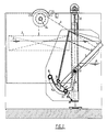
- the weirgate (1) is tilting on the shaft (2).
- the weirgate (1) is held upright against the hydraulic pressure with cable (3) via transmission (4) by a floating counterweight (5).
- the spindle construction (6) can adjust the shaft (2) vertically. In this way the weirlevel (7) can be controlled.
- the downstream weirlevel (8) has some influence on the correct adjustment.
- the lower edge (9) has an attachment (10) for a flexible strip (11) which has its other side attached to the upper edge (12) of a support plate (13) with strengtheners (14).
- the support plate (13) is through bearingsleeves (15) connected to arms (16) welding.
- the arms (16) are rotatably suspended from the shaft (2) of the weirgate (1).
- Through the bearingsleeves (15) goes shaft (17).
- This shaft (17) carries with bearingsleeves (18) a threshold plate (19).
- the threshold plate (19) is movable attached at to a threshold beam (21) fixed to the bottom of the canal.
- a plate (23) is hinged or flexibly attached to the weirgate (1) at (24) reaching over the attachment (12) of the flexible strip offers the possibility to prevent dirt accumulation on the flexible strip (11).
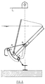
- Support plate (13) serves to support the flexible strip (11). Because the support plate (13) is suspended with arms (16) from the shaft (2) of the weirgate (1), the position of the support of the flexible strip (11) in relation to the lower edge (9) of the weirgate (1) will not change when the spindle construction (6) is used to adjust the shaft (2) of the weirgate (1).
- the flexible strip (11) unwinds between the support plate (13) and the lower edge (9), the distance between the support plate (13) and the lower edge (9) is decisive for the resultant of the hydrostatic forces exerting on the unsupported areas of the flexible strip (11).
- the support plate (13) and the lower edge (9) of the weirgate (1) are both circular formed with axis (2) as centre, the behavior of the flexible strip (11) is neutral.
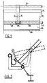
- a progressive or regressive tilting character can be attained. See fig. 5.
- a weir is realised where the lower edge (9) of the weirgate (1) is sealingly connected with the threshold beam (21) on the bottom of the canal, without having any extra frictional losses.
- the tilting effect of the weirgate (1) is not negatively influenced, where with the help of the flexible strip (11) and the profile of the support plate (13) and/or the profile of the lower edge (9) of the weirgate (1) makes an accurate adjustment of the required waterlevel possible.
Landscapes
- Engineering & Computer Science (AREA)
- Structural Engineering (AREA)
- General Engineering & Computer Science (AREA)
- Mechanical Engineering (AREA)
- Civil Engineering (AREA)
- Barrages (AREA)
- Lock And Its Accessories (AREA)
- Preliminary Treatment Of Fibers (AREA)
- Endoscopes (AREA)
- Earth Drilling (AREA)
Claims (12)
- Ecluse comprenant une vanne (1) pouvant basculer autour d'un axe suspendu dans un canal au-dessus du fond de celui-ci, l'axe étant situé entre le bord inférieur et le bord supérieur de la vanne, à distance de ces bords et plus près du bord inférieur que du bord supérieur, la vanne coopérant avec des moyens de commande pour l'ouvrir et la fermer par rotation autour de l'axe, caractérisée en ce qu'un joint flexible (11) est disposé entre le bord inférieur (9) de la vanne et une plaque-support (13) située près du bord inférieur de la vanne et reliée à la poutre (21) formant seuil sur le fond du canal, ce joint permettant le mouvement curviligne du bord inférieur de la vanne tout en empêchant l'eau de s'écouler entre ce bord inférieur et le fond du canal.
- Ecluse selon la revendication 1, caractérisée en ce que le joint flexible comprend une bande (11) en un matériau flexible dont un côté est relié de façon étanche au bord inférieur (9) de la vanne (1), son autre côté étant relié de façon étanche à la plaque-support (13), la distance entre celle-ci et ledit bord inférieur (9) restant toujours inférieure à l'extension de la bande d'un de ses côtés à l'autre.
- Ecluse selon la revendication 2, caractérisée en ce que la partie de la bande (11) proche de sa fixation à la plaque-support (13) est pressée contre celle-ci par la pression de l'eau, et que le reste de la bande s'infléchit en direction du bord inférieur (9) de la vanne (1) en fonction de la position angulaire de cette dernière, de manière à ce que la bande se déroule de la plaque-support lors d'une rotation de la vanne vers sa position ouverte, et vice-versa.
- Ecluse selon la revendication 3, caractérisée en ce que, lorsqu'elle est vue dans un plan perpendiculaire à l'axe, la plaque-support (13) est incurvée essentiellement le long de la trajectoire décrite par le bord inférieur (9) de la vanne lors d'une rotation de celle-ci.
- Ecluse selon la revendication 4, caractérisée en ce que la plaque-support (13) est concentrique à l'axe de la vanne, au moins dans sa partie entrant en contact avec la bande (11).
- Ecluse selon la revendication 4, caractérisée en ce que la plaque-support (13) est non-circulaire, au moins dans sa partie entrant en contact avec la bande (11).
- Ecluse selon la revendication 3, caractérisée en ce que, lorsqu'elle est vue dans un plan perpendiculaire à l'axe, la plaque-support (13) présente un profil angulaire (fig. 5) dont une branche est horizontale et l'autre verticale, le coin intérieur du profil faisant face au bord inférieur de la vanne.
- Ecluse selon une des revendications 3 à 7, caractérisée en ce que la bande (11) est reliée au bord le plus haut de la plaque-support (13) ainsi qu'à un rebord s'étendant à partir du bord inférieur (9) de la vanne.
- Ecluse selon une des revendications précédentes, caractérisée en ce que le pivot (2) de la vanne est suspendu dans un châssis ajustable en direction verticale, la plaque-support étant suspendue au pivot (2) et réunie, de façon étanche et permettant une rotation, à la poutre (21) formant seuil au fond du canal.
- Ecluse selon la revendication 9, caractérisée en ce qu'elle comporte une plaque formant seuil (19) montée à rotation sur le bord inférieur de la plaque-support (13) ainsi que sur la poutre (21) formant seuil au fond du canal.
- Ecluse selon la revendication 10, caractérisée en ce que la plaque-support (13) comporte des bras (16) pouvant pivoter autour du pivot (2) de la vanne, et que l'axe (17) formant charnière entre la plaque-support (13) et la plaque formant seuil (19) est situé hors du plan défini par la charnière (20) entre la plaque formant seuil et la poutre (21) formant seuil au fond du canal, ainsi que par le pivot (2) de la vanne.
- Ecluse selon une des revendications 2 à 11, caractérisée en ce qu'une plaque de protection (23) est montée à rotation sur la vanne et repose sur la plaque-support (13), respectivement sur le bord inférieur (9) de la vanne.
Applications Claiming Priority (3)
| Application Number | Priority Date | Filing Date | Title |
|---|---|---|---|
| NL8901563 | 1989-06-21 | ||
| NL8901563A NL8901563A (nl) | 1989-06-21 | 1989-06-21 | Onderdorpel constructie voor tuimelstuw. |
| PCT/NL1990/000087 WO1990015902A1 (fr) | 1989-06-21 | 1990-06-20 | Construction de seuil pour un deversior basculant |
Publications (2)
| Publication Number | Publication Date |
|---|---|
| EP0438549A1 EP0438549A1 (fr) | 1991-07-31 |
| EP0438549B1 true EP0438549B1 (fr) | 1994-09-14 |
Family
ID=19854872
Family Applications (1)
| Application Number | Title | Priority Date | Filing Date |
|---|---|---|---|
| EP90909778A Expired - Lifetime EP0438549B1 (fr) | 1989-06-21 | 1990-06-20 | Construction de seuil pour un deversior basculant |
Country Status (7)
| Country | Link |
|---|---|
| US (1) | US5171102A (fr) |
| EP (1) | EP0438549B1 (fr) |
| AT (1) | ATE111543T1 (fr) |
| AU (1) | AU5850990A (fr) |
| DE (1) | DE69012543T2 (fr) |
| NL (1) | NL8901563A (fr) |
| WO (1) | WO1990015902A1 (fr) |
Families Citing this family (26)
| Publication number | Priority date | Publication date | Assignee | Title |
|---|---|---|---|---|
| GB9420852D0 (en) * | 1994-10-15 | 1994-11-30 | Timms Cyril A | Adjustable self-regulating tilting weir with manual or fixed action |
| FR2744147B1 (fr) * | 1996-01-26 | 1998-03-20 | Sikora Bernard | Deversoir basculant |
| US5944445A (en) * | 1997-07-10 | 1999-08-31 | Smart Vent, Inc. | Device and method for relieving flooding from enclosed space |
| US6019665A (en) * | 1998-04-30 | 2000-02-01 | Fujitsu Limited | Controlled retention of slurry in chemical mechanical polishing |
| GB9810192D0 (en) * | 1998-05-14 | 1998-07-08 | Timms Cyril A | Self-regulating weirs and fishways |
| US6019898A (en) * | 1998-06-23 | 2000-02-01 | Aqua-Aerobic Systems, Inc. | Weir assembly with movable baffle member |
| GB0127216D0 (en) * | 2001-11-13 | 2002-01-02 | Univ Edinburgh | Watertight gate mechanism |
| US7726907B2 (en) | 2006-08-10 | 2010-06-01 | Mccreedy C Thomas | Automatic trip gate |
| CN201158815Y (zh) * | 2007-12-26 | 2008-12-03 | 李德富 | 拉支式水力自控重力转换启闭闸门 |
| JP5180945B2 (ja) * | 2009-11-24 | 2013-04-10 | 日立造船株式会社 | 起伏ゲート式防波堤の係留装置 |
| JP5971956B2 (ja) * | 2012-01-16 | 2016-08-17 | 日立造船株式会社 | 浮体式フラップゲート |
| US9551153B2 (en) * | 2015-04-08 | 2017-01-24 | Smart Vent Products, Inc. | Scupper door systems |
| US9353569B1 (en) | 2015-04-08 | 2016-05-31 | Smart Vent Products, Inc. | Connectors for a flood vent |
| US9624637B2 (en) | 2015-04-08 | 2017-04-18 | Smart Vent Products, Inc. | Flood vent |
| US9376803B1 (en) | 2015-04-08 | 2016-06-28 | Smart Vent Products, Inc. | Flood vent trigger systems |
| US10113309B2 (en) | 2015-04-08 | 2018-10-30 | Smart Vent Products, Inc. | Flood vent barrier systems |
| EP3339513B1 (fr) * | 2015-09-25 | 2020-03-25 | Terata, Hiroshi | Porte d'écluse |
| US9719249B2 (en) | 2015-12-10 | 2017-08-01 | Smart Vent Products, Inc. | Flood vent having a panel |
| US9758982B2 (en) | 2015-12-10 | 2017-09-12 | Smart Vent Products, Inc. | Flood vent having a panel |
| US9637912B1 (en) | 2015-12-10 | 2017-05-02 | Smart Vent Products, Inc. | Flood vent having a panel |
| US10385611B2 (en) * | 2015-12-10 | 2019-08-20 | Smart Vent Products, Inc. | Flood vent having a panel |
| US10619345B2 (en) * | 2015-12-10 | 2020-04-14 | Smart Vent Products, Inc. | Flood vent having a panel |
| DK179294B1 (da) * | 2017-03-30 | 2018-04-16 | Steen Olsen Invest Aps | Stormflodssikring |
| CN110144859B (zh) * | 2018-02-10 | 2020-09-15 | 扬州市慧宇科技有限公司 | 一种基于物联网的使用寿命长的钢坝闸门 |
| CN110219286A (zh) * | 2019-06-14 | 2019-09-10 | 安徽省(水利部淮河水利委员会)水利科学研究院(安徽省水利工程质量检测中心站) | 一种轻量化的波纹板闸门 |
| CN110700202B (zh) * | 2019-10-17 | 2024-09-10 | 中国电建集团贵阳勘测设计研究院有限公司 | 一种设置于溢流堰的潜孔弧门底水封装置 |
Family Cites Families (9)
| Publication number | Priority date | Publication date | Assignee | Title |
|---|---|---|---|---|
| AT151492B (de) * | 1934-03-20 | 1937-11-10 | Maschf Augsburg Nuernberg Ag | Wehrklappe. |
| US2051359A (en) * | 1934-10-03 | 1936-08-18 | Jr James L Adams | Safety guard gate |
| DE758796C (de) * | 1940-06-08 | 1952-12-15 | Krupp Fried Grusonwerk Ag | Klappenwehr |
| US2759697A (en) * | 1950-10-20 | 1956-08-21 | Fred H Camphausen | Hydraulic control for butterfly valves |
| AT312509B (de) * | 1970-05-19 | 1974-01-10 | Waagner Biro Ag | Dichtung |
| US4103497A (en) * | 1976-04-28 | 1978-08-01 | Pirelli Furlanis - Applicazioni Idrauliche Agricole Gomma S.P.A. | Manoeuvrable weir |
| JPS5715712A (en) * | 1980-06-30 | 1982-01-27 | Mitsubishi Heavy Ind Ltd | Sluice gate tilting toward upstream side |
| US4455106A (en) * | 1981-10-23 | 1984-06-19 | Johnson William M | Flash gate board |
| NL8702118A (nl) * | 1987-09-04 | 1989-04-03 | Waterschap Kromme Rijn | Mechanische automatische tuimelstuw met zelfinstellende verlaging van het stuwpeil tijdens grotere afvoeren. |
-
1989
- 1989-06-21 NL NL8901563A patent/NL8901563A/nl not_active Application Discontinuation
-
1990
- 1990-06-20 DE DE69012543T patent/DE69012543T2/de not_active Expired - Fee Related
- 1990-06-20 EP EP90909778A patent/EP0438549B1/fr not_active Expired - Lifetime
- 1990-06-20 WO PCT/NL1990/000087 patent/WO1990015902A1/fr not_active Ceased
- 1990-06-20 AT AT90909778T patent/ATE111543T1/de not_active IP Right Cessation
- 1990-06-20 AU AU58509/90A patent/AU5850990A/en not_active Abandoned
-
1991
- 1991-10-04 US US07/771,335 patent/US5171102A/en not_active Expired - Fee Related
Also Published As
| Publication number | Publication date |
|---|---|
| NL8901563A (nl) | 1991-01-16 |
| WO1990015902A1 (fr) | 1990-12-27 |
| DE69012543D1 (de) | 1994-10-20 |
| AU5850990A (en) | 1991-01-08 |
| DE69012543T2 (de) | 1995-04-13 |
| EP0438549A1 (fr) | 1991-07-31 |
| ATE111543T1 (de) | 1994-09-15 |
| US5171102A (en) | 1992-12-15 |
Similar Documents
| Publication | Publication Date | Title |
|---|---|---|
| EP0438549B1 (fr) | Construction de seuil pour un deversior basculant | |
| US5984575A (en) | Flood flow modulator | |
| AU759647B2 (en) | Self-regulating weirs and fishways | |
| CA1325727C (fr) | Garnitures d'etancheite a l'eau pour glissoires d'eau | |
| US9279242B2 (en) | Drain grate system and method | |
| CN100540816C (zh) | 防止脏物流入截流污水管中的装置 | |
| US5125766A (en) | Mechanical automatic tilting weir with selfadjusting lowering of the weir-level during larger discharges | |
| US5468090A (en) | Bending weir | |
| US5123444A (en) | Back flow blocker in sloping pipes | |
| KR101786985B1 (ko) | 어도 겸용 수문 | |
| KR20060122333A (ko) | 전도식 어도 수문 | |
| RU2144969C1 (ru) | Устройство для регулирования уровня воды в закрытой дренажной сети | |
| KR20130000680A (ko) | 경사 도로의 노면 배수처리용 스틸 그레이팅 | |
| JPH0260806B2 (fr) | ||
| KR200364488Y1 (ko) | 하천의 방류량 조절기구를 갖춘 제방축조물 | |
| US970308A (en) | Ditch-gate. | |
| KR200392599Y1 (ko) | 전도식 어도 수문 | |
| RU2019868C1 (ru) | Гидравлический стабилизатор расхода воды в открытом канале | |
| US657774A (en) | Water-gate. | |
| JP7053060B2 (ja) | フラップゲート | |
| JPS6015775Y2 (ja) | 堤内排水口用自在開閉扉 | |
| SU1105546A1 (ru) | Вододействующий затвор | |
| KR102072198B1 (ko) | 무동력 다기능 게이트 | |
| JPH0116168Y2 (fr) | ||
| JP3822715B2 (ja) | 樋管用逆流防止ゲート |
Legal Events
| Date | Code | Title | Description |
|---|---|---|---|
| PUAI | Public reference made under article 153(3) epc to a published international application that has entered the european phase |
Free format text: ORIGINAL CODE: 0009012 |
|
| 17P | Request for examination filed |
Effective date: 19910522 |
|
| AK | Designated contracting states |
Kind code of ref document: A1 Designated state(s): AT BE CH DE DK ES FR GB IT LI LU NL SE |
|
| 17Q | First examination report despatched |
Effective date: 19931105 |
|
| GRAA | (expected) grant |
Free format text: ORIGINAL CODE: 0009210 |
|
| AK | Designated contracting states |
Kind code of ref document: B1 Designated state(s): AT BE CH DE DK ES FR GB IT LI LU NL SE |
|
| PG25 | Lapsed in a contracting state [announced via postgrant information from national office to epo] |
Ref country code: IT Free format text: LAPSE BECAUSE OF FAILURE TO SUBMIT A TRANSLATION OF THE DESCRIPTION OR TO PAY THE FEE WITHIN THE PRESCRIBED TIME-LIMIT;WARNING: LAPSES OF ITALIAN PATENTS WITH EFFECTIVE DATE BEFORE 2007 MAY HAVE OCCURRED AT ANY TIME BEFORE 2007. THE CORRECT EFFECTIVE DATE MAY BE DIFFERENT FROM THE ONE RECORDED. Effective date: 19940914 Ref country code: FR Effective date: 19940914 Ref country code: LI Effective date: 19940914 Ref country code: ES Free format text: THE PATENT HAS BEEN ANNULLED BY A DECISION OF A NATIONAL AUTHORITY Effective date: 19940914 Ref country code: CH Effective date: 19940914 Ref country code: AT Effective date: 19940914 Ref country code: DK Effective date: 19940914 |
|
| REF | Corresponds to: |
Ref document number: 111543 Country of ref document: AT Date of ref document: 19940915 Kind code of ref document: T |
|
| REF | Corresponds to: |
Ref document number: 69012543 Country of ref document: DE Date of ref document: 19941020 |
|
| PG25 | Lapsed in a contracting state [announced via postgrant information from national office to epo] |
Ref country code: SE Effective date: 19941214 |
|
| REG | Reference to a national code |
Ref country code: CH Ref legal event code: PL |
|
| EN | Fr: translation not filed | ||
| PG25 | Lapsed in a contracting state [announced via postgrant information from national office to epo] |
Ref country code: GB Effective date: 19950620 |
|
| PG25 | Lapsed in a contracting state [announced via postgrant information from national office to epo] |
Ref country code: LU Free format text: LAPSE BECAUSE OF NON-PAYMENT OF DUE FEES Effective date: 19950630 |
|
| PLBE | No opposition filed within time limit |
Free format text: ORIGINAL CODE: 0009261 |
|
| STAA | Information on the status of an ep patent application or granted ep patent |
Free format text: STATUS: NO OPPOSITION FILED WITHIN TIME LIMIT |
|
| 26N | No opposition filed | ||
| GBPC | Gb: european patent ceased through non-payment of renewal fee |
Effective date: 19950620 |
|
| PGFP | Annual fee paid to national office [announced via postgrant information from national office to epo] |
Ref country code: BE Payment date: 19970624 Year of fee payment: 8 |
|
| PGFP | Annual fee paid to national office [announced via postgrant information from national office to epo] |
Ref country code: DE Payment date: 19970722 Year of fee payment: 8 |
|
| PG25 | Lapsed in a contracting state [announced via postgrant information from national office to epo] |
Ref country code: BE Free format text: LAPSE BECAUSE OF NON-PAYMENT OF DUE FEES Effective date: 19980630 |
|
| PGFP | Annual fee paid to national office [announced via postgrant information from national office to epo] |
Ref country code: NL Payment date: 19980630 Year of fee payment: 9 |
|
| BERE | Be: lapsed |
Owner name: WATERSCHAP KROMME RIJN Effective date: 19980630 |
|
| PG25 | Lapsed in a contracting state [announced via postgrant information from national office to epo] |
Ref country code: DE Free format text: LAPSE BECAUSE OF NON-PAYMENT OF DUE FEES Effective date: 19990401 |
|
| PG25 | Lapsed in a contracting state [announced via postgrant information from national office to epo] |
Ref country code: NL Free format text: LAPSE BECAUSE OF NON-PAYMENT OF DUE FEES Effective date: 20000101 |
|
| NLV4 | Nl: lapsed or anulled due to non-payment of the annual fee |
Effective date: 20000101 |