EP0438604A1 - Hydraulische schaltungsanordnung - Google Patents
Hydraulische schaltungsanordnung Download PDFInfo
- Publication number
- EP0438604A1 EP0438604A1 EP90912374A EP90912374A EP0438604A1 EP 0438604 A1 EP0438604 A1 EP 0438604A1 EP 90912374 A EP90912374 A EP 90912374A EP 90912374 A EP90912374 A EP 90912374A EP 0438604 A1 EP0438604 A1 EP 0438604A1
- Authority
- EP
- European Patent Office
- Prior art keywords
- bleed
- valves
- operating valves
- actuators
- circuit
- Prior art date
- Legal status (The legal status is an assumption and is not a legal conclusion. Google has not performed a legal analysis and makes no representation as to the accuracy of the status listed.)
- Granted
Links
Images

Classifications
-
- F—MECHANICAL ENGINEERING; LIGHTING; HEATING; WEAPONS; BLASTING
- F15—FLUID-PRESSURE ACTUATORS; HYDRAULICS OR PNEUMATICS IN GENERAL
- F15B—SYSTEMS ACTING BY MEANS OF FLUIDS IN GENERAL; FLUID-PRESSURE ACTUATORS, e.g. SERVOMOTORS; DETAILS OF FLUID-PRESSURE SYSTEMS, NOT OTHERWISE PROVIDED FOR
- F15B11/00—Servomotor systems without provision for follow-up action; Circuits therefor
-
- F—MECHANICAL ENGINEERING; LIGHTING; HEATING; WEAPONS; BLASTING
- F15—FLUID-PRESSURE ACTUATORS; HYDRAULICS OR PNEUMATICS IN GENERAL
- F15B—SYSTEMS ACTING BY MEANS OF FLUIDS IN GENERAL; FLUID-PRESSURE ACTUATORS, e.g. SERVOMOTORS; DETAILS OF FLUID-PRESSURE SYSTEMS, NOT OTHERWISE PROVIDED FOR
- F15B13/00—Details of servomotor systems ; Valves for servomotor systems
- F15B13/02—Fluid distribution or supply devices characterised by their adaptation to the control of servomotors
- F15B13/04—Fluid distribution or supply devices characterised by their adaptation to the control of servomotors for use with a single servomotor
- F15B13/042—Fluid distribution or supply devices characterised by their adaptation to the control of servomotors for use with a single servomotor operated by fluid pressure
- F15B13/0422—Fluid distribution or supply devices characterised by their adaptation to the control of servomotors for use with a single servomotor operated by fluid pressure with manually-operated pilot valves, e.g. joysticks
Definitions
- This invention relates to a hydraulic circuit apparatus for supplying fluid under pressure to a plurality of actuators.
- a hydraulic circuit is heretofore known which comprises a plurality of closed-center type operating valves provided in discharge passage of a hydraulic pump and adapted to supply fluid under pressure discharged by the pump to a plurality of actuators.
- a pressure compensating valve is provided in a circuit connecting each of the operating valves with each of the actuators, and each of the pressure compensating valves is set at the highest load pressure out of load pressures exerted on each of the actuators so that when the plurality of operating valves are operated at the same time the pressurized fluid discharged by one set of hydraulic pump can be supplied to the plurality of actuators with different load pressures.
- the hydraulic circuit apparatus is arranged such that when the operating valves are kept at their neutral positions the discharge side of the pump is not allowed to communicate through the operating valves with a fluid tank. Therefore, when the operating valves are kept at their respective neutral positions, the fluid under pressure discharged by the hydraulic pump is compressed between the outlet of the pump and the operating valves, and hence the stability of the actuators when operating the operating valves suddenly becomes inferior to that in case open-center type operating valves are used which are arranged to communicate the discharge side of the hydraulic pump with the fluid tank when the operating are kept at their neutral positions.
- the arrangement is made such that excessive increase in the pressure on the discharge side of the hydraulic pump is prevented by reducing the flow rate of the fluid discharged by the pump substantially to zero; stating more concretely, by reducing the flow rate of fluid to about 5% of the maximum dischrage flow rate; that is, to such a minimum allowable extent that leakage of fluid in every part of the hydraulic circuit can be compensated sufficiently.
- the present invention has been devised in view of the above-mentioned circumstances in the prior art, and has for its object to provide a hydraulic circuit apparatus wherein the stability of each of actuators when operating each of operating valves suddenly can be improved; the flow rate of the fluid under pressure discharged by a variable displacement when each of the operating valves is kept at its neutral position can be increased so as to improve the response of the hydraulic circuit; and also when the fluid under pressure discharged by the pump is supplied into each of the actuators, satisfactory pressure compensation can be conducted in the same manner as in the prior art hydraulic circuit apparatus.
- a hydraulic circuit apparatus having closed-center type operating valves provided in the discharge passage of a variable displacement pump and the number of which is the same as that of actuators, and pressure compensating valves each being provided in a circuit connecting each of these operating valves with each of the actuators, each of the pressure compensating valves being set at a pressure corresponding to the highest value out of load pressures exerted on the actuators, wherein the apparatus comprises a bleed-off circuit connecting the discharge passage of the variable displacement pump with a fluid tank; and a bleed-off valve provided in the bleed-off circuit and adapted to be kept at its communicating position when each of the operating valves assumes its neutral position; and also kept at its shut-off position when each of the operating valves assumes either its first pressurized fluid supply position or its second pressurized fluid supply position.
- a hydraulic circuit apparatus having closed-center type operating valves provided in the discharge passage of a variable displacement pump and the number of which is the same as that of actuators, and pressure compensating valves each being provided in a circuit connecting each of these operating valves with each of the actuators, each of the pressure compensating valves being set at a pressure corresponding to the highest value out of load pressures exerted on the actuators, wherein the apparatus comprises a bleed-off circuit connecting the discharge passage of the variable displacement pump with a fluid tank; a bleed-off valve provided in the bleed-off circuit and adapted to be kept at its communicating position when each of the operating valves assumes its neutral position, and also kept at its shut-off position when each of the operating valves assumes either its first pressurized fluid supply position or its second pressurized fluid position; and a flow restrictor provided in the bleed-off circuit.
- the bleed-off valve assumes its communicating position so as to allow the fluid under pressure discharged by the variable displacement pump to flow into the fluid tank or reservoir, the pressurized fluid discharged by the pump is not compressed between the outlet thereof and the operating valves so that the pressure in the discharge side of the pump is prevented from rising excessively, and also when each of the operating valves is changed over either to its first pressurized fluid supply position or to its second pressurized fluid position, the bleed-off valve is changed over to its shut-off position so that the fluid under pressure discharged by the pump is prevented from flowing into the fluid tank.
- a fluid discharge passage 1a of a variable displacement 1 is connected with inlets of a plurality of closed-centre type operating valves 2, and the outlet of each of the operating valves 2 is connected through its pressure compensating valve 3 with an actuator 4.
- the pressure in the outlets of the operating valves 2; that is, the load pressures exerted on the actuators 4 are compared by a shuttle valve 5, and the highest outlet pressure; that is, the highest load pressure Po out of load pressures exerted on the actuators 4 is supplied into the spring chambers of the compensating valves 3 so that the latter valves 3 are set at a pressure corresponding to the highest load pressure Po.
- variable displacement pump 1 has a swash plate 1b adapted to be actuated by a control arrangement 6 on the basis of a difference between the discharge pressure P and the above-mentioned load pressure Po so that its tilting angle, and hence the flow rate of fluid discharged thereby can be controlled.
- Each of the above-mentioned operating valves 2 is normally kept at its neutral position and is changed over either to its first fluid supply portion or to its second fluid supply position by pilot fluid under pressure supplied either to a first pressure receiving section 21 or to a second pressure receiving position 22.
- the first and second pressure receiving sections 21 and 22 are each supplied with pilot fluid under pressure from pilot valves 7 associated therewith.
- each pilot valve 7 When each of the above-mentioned pilot valves 7 is operated by means of an operating lever 8, it will deliver pilot fluid under pressure either into its first port 7a or into its second port 7b, and the delivery pressure is proportional to the operational stroke of the operating lever 8.
- the first and second ports 7a and 7b of each pilot valve 7 are connected with the first and second pressure receiving sections 21 and 22, respectively of each operating valve 2, and also with first and second inlets 9a and 9b, respectively, of each shuttle valves 9, whose outlets 9c are connected with a valve 10.
- the discharge passage 1a of the above-mentioned variable displacement pump 1 is communicated through a bleed-off circuit 11 with a fluid tank.
- the bleed-off circuit 11 is provided with a bleed-off valve 12 and a flow restrictor 13.
- the bleed-off valve 12 is normally kept by the resilient force of a spring mounted therein at its communicating position I, and is adapted to be changed over to its shut-off position II by a force which is proportional to pilot fluid pressure supplied to its pressure receiving section 12a.
- the pressure receiving section 12a is connected with the above-mentioned valve 10.
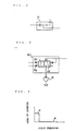
- the above-mentioned valve 10 is of a shuttle valve as shown in Fig. 2, and its outlet is connected with the pressure receiving section 12a.
- the pilot valves 7 are also kept in neutral condition so that their first and second ports 7a and 7b are not supplied with pilot fluid under pressure.
- the pressure receiving section 12a of the bleed-off valve 12 is not supplied with pilot fluid under pressure, and therefore the valves 12 are kept at their communicating positions I, and the area of opening of each of the valves 12 becomes the largest value as shown in Fig. 4.
- the pressurized fluid discharged by the variable displacement pump 1 will flow through the bleed-off circuit 11 into the fluid tank, and the pressure in the discharge path 1a; that is, the discharge pressure P is set at a predetermined value by the action of the flow restrictor 13 provided in the bleed-off circuit 11.
- the discharge pressure P is then transmitted to the control arrangement 6 to increase the tilting angle of the swash plate 1b to thereby increase the flow rate of the fluid discharged by the variable displacement pump 1, and also the fluid discharged by the pump 1 is not compressed in the circuit between its discharge side and the operating valve 2, and so the discharge pressure will not increase at all.
- the stability of the actuators 4 when operating the operating valves 2 suddenly can be improved, and also the flow rate of the fluid discharged by the variable displacement pump 1 can be increased so as to improve the response of the hydraulic circuit when operating the operating valves 2 suddenly.
- the pilot valves 7 are operated so as to supply pilot fluid under pressure either to the first pressure receiving sections 21 of the operating valves 2 or to the second pressure receiving sections 22 thereof thereby keeping the operating valves at their first or second pressurized fluid supply position
- the pilot fluid under pressure is supplied through the shuttle valve 9 and the valve 10 into the pressure receiving section 12a of the bleed-off valve 12.
- the bleed-off valve 12 is switched over gradually to its shut-off position II by the pilot fluid pressure, and is kept at the shut-off position II when the pilot pressure has reached a predetermined value.
- the area of opening of the bleed-off valve 12 becomes zero as shown by "b" in Fig.
- the flow restrictor 13 may be provided on the side of the outlet of the bleed-off valve 12. This is applicable to a hydraulic circuit comprising three or more operating valves 2.
- valve 10 may be constructed as shown in Fig. 3.
- valve 10 is normally kept by the resilient force of a valve mounted at its shut-off position II, and is arranged to be switched over to its communicating position I by pilot fluid under pressure supplied to its first and second pressure receiving sections 101 and 102, which are connected with the outlets of the above-mentioned shuttle valves 9.
- the arrangement is made such that when the pilot valves 7 are operated to switch the operating valves 2 over either to their first pressurized fluid supply position or to their second pressurized fluid supply position, the pressurized fluid discharged by a pilot fluid supply pump 14 is not allowed to be supplied to the pressure receiving section 12a of the bleed-off valve 12.
Landscapes
- Engineering & Computer Science (AREA)
- Physics & Mathematics (AREA)
- Fluid Mechanics (AREA)
- Mechanical Engineering (AREA)
- General Engineering & Computer Science (AREA)
- Fluid-Pressure Circuits (AREA)
Applications Claiming Priority (5)
| Application Number | Priority Date | Filing Date | Title |
|---|---|---|---|
| JP210051/89 | 1989-08-16 | ||
| JP21005189A JPH0374606A (ja) | 1989-08-16 | 1989-08-16 | 油圧回路 |
| JP21005289A JPH0374607A (ja) | 1989-08-16 | 1989-08-16 | 油圧回路 |
| JP210052/89 | 1989-08-16 | ||
| PCT/JP1990/001049 WO1991002903A1 (fr) | 1989-08-16 | 1990-08-16 | Dispositif de circuit hydraulique |
Publications (3)
| Publication Number | Publication Date |
|---|---|
| EP0438604A1 true EP0438604A1 (de) | 1991-07-31 |
| EP0438604A4 EP0438604A4 (en) | 1993-04-28 |
| EP0438604B1 EP0438604B1 (de) | 1997-02-05 |
Family
ID=26517834
Family Applications (1)
| Application Number | Title | Priority Date | Filing Date |
|---|---|---|---|
| EP90912374A Expired - Lifetime EP0438604B1 (de) | 1989-08-16 | 1990-08-16 | Hydraulische schaltungsanordnung |
Country Status (5)
| Country | Link |
|---|---|
| US (1) | US5212950A (de) |
| EP (1) | EP0438604B1 (de) |
| KR (1) | KR920701693A (de) |
| DE (1) | DE69029904T2 (de) |
| WO (1) | WO1991002903A1 (de) |
Cited By (1)
| Publication number | Priority date | Publication date | Assignee | Title |
|---|---|---|---|---|
| WO2006005496A1 (de) * | 2004-07-09 | 2006-01-19 | Bosch Rexroth Ag | Hubwerksventilanordnung |
Families Citing this family (8)
| Publication number | Priority date | Publication date | Assignee | Title |
|---|---|---|---|---|
| US5333449A (en) * | 1991-09-02 | 1994-08-02 | Hitachi Construction Machinery Co., Ltd. | Pressure compensating valve assembly |
| JPH06173904A (ja) * | 1992-12-08 | 1994-06-21 | Komatsu Ltd | 旋回用油圧回路 |
| US5626070A (en) * | 1996-02-29 | 1997-05-06 | Caterpillar Inc. | Control logic for a multiple use hydraulic system |
| US7331175B2 (en) * | 2005-08-31 | 2008-02-19 | Caterpillar Inc. | Hydraulic system having area controlled bypass |
| US7320216B2 (en) * | 2005-10-31 | 2008-01-22 | Caterpillar Inc. | Hydraulic system having pressure compensated bypass |
| JP5388787B2 (ja) * | 2009-10-15 | 2014-01-15 | 日立建機株式会社 | 作業機械の油圧システム |
| JP6947711B2 (ja) * | 2018-09-28 | 2021-10-13 | 日立建機株式会社 | 建設機械 |
| CN116981851A (zh) * | 2021-03-18 | 2023-10-31 | 日立建机株式会社 | 作业机械 |
Family Cites Families (24)
| Publication number | Priority date | Publication date | Assignee | Title |
|---|---|---|---|---|
| US3520231A (en) * | 1968-10-23 | 1970-07-14 | Gen Signal Corp | Hydraulic supply systems with flow rate-limiting control |
| US3628424A (en) * | 1970-05-14 | 1971-12-21 | Gen Signal Corp | Hydraulic power circuits employing remotely controlled directional control valves |
| US3646959A (en) * | 1970-10-12 | 1972-03-07 | Sperry Rand Corp | Power transmission |
| DE2244445C3 (de) * | 1972-09-11 | 1981-06-25 | Robert Bosch Gmbh, 7000 Stuttgart | Hydraulische Einrichtung zum Steuern der Druckmittelwege in einer Anlage mit wenigstens einem doppelwirkenden Servomotor |
| US3952509A (en) * | 1975-04-10 | 1976-04-27 | Allis-Chalmers Corporation | Hydraulic system combining open center and closed center hydraulic circuits |
| US4065922A (en) * | 1976-08-23 | 1978-01-03 | Hyster Company | Load lifting and lowering control system |
| US4193263A (en) * | 1978-07-27 | 1980-03-18 | Borg-Warner Corporation | Fluid control system with individually variable flow control mechanism for each control section |
| US4611528A (en) * | 1981-11-12 | 1986-09-16 | Vickers, Incorporated | Power transmission |
| JPS612908A (ja) * | 1984-06-14 | 1986-01-08 | Toshiba Mach Co Ltd | 制御弁装置 |
| DE3447709C1 (de) * | 1984-12-28 | 1986-04-30 | Karl 7298 Loßburg Hehl | Steuervorrichtung fuer den hydraulischen Kreislauf einer Kunststoff-Spritzgiessmaschine |
| DE3532816A1 (de) * | 1985-09-13 | 1987-03-26 | Rexroth Mannesmann Gmbh | Steueranordnung fuer mindestens zwei von mindestens einer pumpe gespeiste hydraulische verbraucher |
| DE3535771A1 (de) * | 1985-10-07 | 1987-04-09 | Linde Ag | Hydrostatischer antrieb mit mehreren verbrauchern |
| DE3644736C2 (de) * | 1985-12-30 | 1996-01-11 | Rexroth Mannesmann Gmbh | Steueranordnung für mindestens zwei von mindestens einer Pumpe gespeiste hydraulische Verbraucher |
| DE3644745A1 (de) * | 1986-12-30 | 1988-07-14 | Rexroth Mannesmann Gmbh | Steueranordnung fuer mindestens zwei von mindestens einer pumpe gespeiste hydraulische verbraucher |
| JP2677803B2 (ja) * | 1987-11-25 | 1997-11-17 | 日立建機株式会社 | 油圧駆動装置 |
| EP0366815B1 (de) * | 1988-05-10 | 1993-11-24 | Hitachi Construction Machinery Co., Ltd. | Hydraulische antriebseinheit für baumaschinen |
| IN170798B (de) * | 1988-05-12 | 1992-05-23 | Hitachi Construction Machinery | |
| DE69029633T2 (de) * | 1989-03-22 | 1997-05-07 | Hitachi Construction Machinery | Hydraulisches antriebssystem für das bauwesen und für baumaschinen |
| JPH02261903A (ja) * | 1989-03-31 | 1990-10-24 | Komatsu Ltd | クローズドセンタ・ロードセンシングシステムにおける油圧回路 |
| KR950004530B1 (ko) * | 1989-08-16 | 1995-05-02 | 히다찌 겐끼 가부시기가이샤 | 밸브장치 및 유압회로장치 |
| US5101628A (en) * | 1990-01-22 | 1992-04-07 | Shin Caterpillar Mitsubishi Ltd. | Energy regenerative circuit in a hydraulic apparatus |
| US4977928A (en) * | 1990-05-07 | 1990-12-18 | Caterpillar Inc. | Load sensing hydraulic system |
| JP2828490B2 (ja) * | 1990-06-19 | 1998-11-25 | 日立建機株式会社 | ロードセンシング油圧駆動回路の制御装置 |
| US5129229A (en) * | 1990-06-19 | 1992-07-14 | Hitachi Construction Machinery Co., Ltd. | Hydraulic drive system for civil-engineering and construction machine |
-
1990
- 1990-08-16 DE DE69029904T patent/DE69029904T2/de not_active Expired - Fee Related
- 1990-08-16 EP EP90912374A patent/EP0438604B1/de not_active Expired - Lifetime
- 1990-08-16 WO PCT/JP1990/001049 patent/WO1991002903A1/ja not_active Ceased
-
1991
- 1991-04-15 KR KR1019910700374A patent/KR920701693A/ko not_active Ceased
-
1992
- 1992-05-06 US US07/882,367 patent/US5212950A/en not_active Expired - Lifetime
Cited By (2)
| Publication number | Priority date | Publication date | Assignee | Title |
|---|---|---|---|---|
| WO2006005496A1 (de) * | 2004-07-09 | 2006-01-19 | Bosch Rexroth Ag | Hubwerksventilanordnung |
| US8020485B2 (en) | 2004-07-09 | 2011-09-20 | Bosch Rexroth Ag | Lifting gear valve arrangement |
Also Published As
| Publication number | Publication date |
|---|---|
| WO1991002903A1 (fr) | 1991-03-07 |
| US5212950A (en) | 1993-05-25 |
| KR920701693A (ko) | 1992-08-12 |
| EP0438604B1 (de) | 1997-02-05 |
| DE69029904T2 (de) | 1997-05-22 |
| DE69029904D1 (de) | 1997-03-20 |
| EP0438604A4 (en) | 1993-04-28 |
Similar Documents
| Publication | Publication Date | Title |
|---|---|---|
| AU646429B2 (en) | Load check and pressure compensating valve | |
| US6026730A (en) | Flow control apparatus in a hydraulic circuit | |
| US5419129A (en) | Hydraulic system for open or closed-centered systems | |
| US5845678A (en) | Pressurized fluid supply system | |
| US20090094972A1 (en) | Hydraulic control assembly | |
| EP0516864A4 (en) | Hydraulic driving system and direction change-over valves | |
| US5279122A (en) | Hydraulic circuit apparatus for supplying fluid under pressure into hydraulic cylinders for work implement | |
| EP0438604B1 (de) | Hydraulische schaltungsanordnung | |
| EP0667452B1 (de) | Kapazitätsregelvorrichtung für hydraulische pumpe mit veränderlicher fördermenge | |
| EP0439621A1 (de) | Zufuhrschaltungsvorrichtung für öl unter druck zum hydraulischem kolben einer baustellenvorrichtung | |
| US5673557A (en) | Displacement control system for variable displacement type hydraulic pump | |
| KR940008827B1 (ko) | 액튜에이터 구동회로에 있어서의 절환밸브의 파이롯트 압력제어회로 | |
| US5081905A (en) | Hydraulic pilot operation circuit and valve for quickly discharging oil | |
| US7328646B2 (en) | Hydraulic valve arrangement | |
| US5738134A (en) | Pressure compensation valve | |
| US4955444A (en) | Hydrostatic steering device | |
| US5188147A (en) | Pressure compensating type hydraulic valve | |
| US5730182A (en) | Pressure compensation valve | |
| KR20240016224A (ko) | 유압 밸브 조립체 | |
| JP2622401B2 (ja) | 油圧流量制御装置 | |
| EP0116739A2 (de) | Hydraulisches Ventil | |
| JPS6132521B2 (de) | ||
| US4683909A (en) | Reservoir loading valve with pressure protection of the reservoir circuit | |
| JP3672722B2 (ja) | 油圧制御装置 | |
| EP0039473B1 (de) | Hydraulisches Kraftübertragungssystem |
Legal Events
| Date | Code | Title | Description |
|---|---|---|---|
| PUAI | Public reference made under article 153(3) epc to a published international application that has entered the european phase |
Free format text: ORIGINAL CODE: 0009012 |
|
| AK | Designated contracting states |
Kind code of ref document: A1 Designated state(s): DE FR GB IT |
|
| 17P | Request for examination filed |
Effective date: 19910618 |
|
| A4 | Supplementary search report drawn up and despatched | ||
| AK | Designated contracting states |
Kind code of ref document: A4 Designated state(s): DE FR GB IT |
|
| 17Q | First examination report despatched |
Effective date: 19941215 |
|
| GRAG | Despatch of communication of intention to grant |
Free format text: ORIGINAL CODE: EPIDOS AGRA |
|
| GRAH | Despatch of communication of intention to grant a patent |
Free format text: ORIGINAL CODE: EPIDOS IGRA |
|
| GRAH | Despatch of communication of intention to grant a patent |
Free format text: ORIGINAL CODE: EPIDOS IGRA |
|
| GRAA | (expected) grant |
Free format text: ORIGINAL CODE: 0009210 |
|
| AK | Designated contracting states |
Kind code of ref document: B1 Designated state(s): DE FR GB IT |
|
| ITF | It: translation for a ep patent filed | ||
| REF | Corresponds to: |
Ref document number: 69029904 Country of ref document: DE Date of ref document: 19970320 |
|
| ET | Fr: translation filed | ||
| PGFP | Annual fee paid to national office [announced via postgrant information from national office to epo] |
Ref country code: GB Payment date: 19970807 Year of fee payment: 8 |
|
| PGFP | Annual fee paid to national office [announced via postgrant information from national office to epo] |
Ref country code: FR Payment date: 19970811 Year of fee payment: 8 |
|
| PLBE | No opposition filed within time limit |
Free format text: ORIGINAL CODE: 0009261 |
|
| STAA | Information on the status of an ep patent application or granted ep patent |
Free format text: STATUS: NO OPPOSITION FILED WITHIN TIME LIMIT |
|
| 26N | No opposition filed | ||
| PG25 | Lapsed in a contracting state [announced via postgrant information from national office to epo] |
Ref country code: GB Free format text: LAPSE BECAUSE OF NON-PAYMENT OF DUE FEES Effective date: 19980816 |
|
| GBPC | Gb: european patent ceased through non-payment of renewal fee |
Effective date: 19980816 |
|
| PG25 | Lapsed in a contracting state [announced via postgrant information from national office to epo] |
Ref country code: FR Free format text: LAPSE BECAUSE OF NON-PAYMENT OF DUE FEES Effective date: 19990430 |
|
| REG | Reference to a national code |
Ref country code: FR Ref legal event code: ST |
|
| PGFP | Annual fee paid to national office [announced via postgrant information from national office to epo] |
Ref country code: DE Payment date: 19990816 Year of fee payment: 10 |
|
| PG25 | Lapsed in a contracting state [announced via postgrant information from national office to epo] |
Ref country code: DE Free format text: LAPSE BECAUSE OF NON-PAYMENT OF DUE FEES Effective date: 20010501 |
|
| PG25 | Lapsed in a contracting state [announced via postgrant information from national office to epo] |
Ref country code: IT Free format text: LAPSE BECAUSE OF NON-PAYMENT OF DUE FEES;WARNING: LAPSES OF ITALIAN PATENTS WITH EFFECTIVE DATE BEFORE 2007 MAY HAVE OCCURRED AT ANY TIME BEFORE 2007. THE CORRECT EFFECTIVE DATE MAY BE DIFFERENT FROM THE ONE RECORDED. Effective date: 20050816 |