EP0438702B1 - Registratur-Tragkoffer - Google Patents
Registratur-Tragkoffer Download PDFInfo
- Publication number
- EP0438702B1 EP0438702B1 EP90123972A EP90123972A EP0438702B1 EP 0438702 B1 EP0438702 B1 EP 0438702B1 EP 90123972 A EP90123972 A EP 90123972A EP 90123972 A EP90123972 A EP 90123972A EP 0438702 B1 EP0438702 B1 EP 0438702B1
- Authority
- EP
- European Patent Office
- Prior art keywords
- lid
- carrying case
- folding handle
- case
- handle
- Prior art date
- Legal status (The legal status is an assumption and is not a legal conclusion. Google has not performed a legal analysis and makes no representation as to the accuracy of the status listed.)
- Expired - Lifetime
Links
- 238000003780 insertion Methods 0.000 claims description 4
- 230000037431 insertion Effects 0.000 claims description 4
- 238000010276 construction Methods 0.000 abstract description 2
- 239000000463 material Substances 0.000 description 8
- 239000000725 suspension Substances 0.000 description 6
- 230000000903 blocking effect Effects 0.000 description 4
- 238000000034 method Methods 0.000 description 4
- 238000013461 design Methods 0.000 description 3
- 238000001746 injection moulding Methods 0.000 description 3
- 239000000696 magnetic material Substances 0.000 description 3
- 238000011161 development Methods 0.000 description 2
- 230000018109 developmental process Effects 0.000 description 2
- 230000002349 favourable effect Effects 0.000 description 2
- 210000003128 head Anatomy 0.000 description 2
- 238000007654 immersion Methods 0.000 description 2
- 238000007689 inspection Methods 0.000 description 2
- 230000006641 stabilisation Effects 0.000 description 2
- 238000011105 stabilization Methods 0.000 description 2
- 238000012549 training Methods 0.000 description 2
- RZVAJINKPMORJF-UHFFFAOYSA-N Acetaminophen Chemical compound CC(=O)NC1=CC=C(O)C=C1 RZVAJINKPMORJF-UHFFFAOYSA-N 0.000 description 1
- 230000035508 accumulation Effects 0.000 description 1
- 238000009825 accumulation Methods 0.000 description 1
- 239000000853 adhesive Substances 0.000 description 1
- 230000001070 adhesive effect Effects 0.000 description 1
- 238000012937 correction Methods 0.000 description 1
- 230000006378 damage Effects 0.000 description 1
- 238000005516 engineering process Methods 0.000 description 1
- 239000006260 foam Substances 0.000 description 1
- 230000002093 peripheral effect Effects 0.000 description 1
- 230000036316 preload Effects 0.000 description 1
- 230000001681 protective effect Effects 0.000 description 1
- IHQKEDIOMGYHEB-UHFFFAOYSA-M sodium dimethylarsinate Chemical class [Na+].C[As](C)([O-])=O IHQKEDIOMGYHEB-UHFFFAOYSA-M 0.000 description 1
- 238000005507 spraying Methods 0.000 description 1
Images



Classifications
-
- A—HUMAN NECESSITIES
- A45—HAND OR TRAVELLING ARTICLES
- A45C—PURSES; LUGGAGE; HAND CARRIED BAGS
- A45C13/00—Details; Accessories
- A45C13/26—Special adaptations of handles
-
- B—PERFORMING OPERATIONS; TRANSPORTING
- B42—BOOKBINDING; ALBUMS; FILES; SPECIAL PRINTED MATTER
- B42F—SHEETS TEMPORARILY ATTACHED TOGETHER; FILING APPLIANCES; FILE CARDS; INDEXING
- B42F15/00—Suspended filing appliances
- B42F15/007—Support structures for suspended files
- B42F15/0082—Support structures for suspended files with a fixed support
- B42F15/0094—Support structures for suspended files with a fixed support with access from above
Definitions
- the invention relates to a carrying case according to the preamble of claim 1.
- a carrying case of this type is known from DE-U-86 10 225.
- the carrying handle is articulated there as a folding handle near the opening edge of the lower part of the case. It has a bow shape and has legs long enough that the folding handle can be freely pivoted over a cap-shaped, attachable lid, so that an upright gripping position is provided. In this position, a rotary bolt seated on the articulation point with a retaining lug engages over a counter lug on the lid, so that the lid is tied.
- the suitcase is then only accessible again when the folding handle has been pivoted out of the area of the opening of the lower part of the suitcase.
- the turnbuckle and folding handle are not in one piece and therefore rely on a kind of frictional towing. However, this is due to a lack of functional reliability, which is why the locking device is also open for inspection and correction.
- a carrying case for a suspension file is known from DE-A-28 09 705.
- the carrying handle is an integral part of the cover realized as a hinged cover, in the form of a strip-shaped bridge spanning a depression in the cover cover.
- the lower part of the case can be telescopically enlarged for easier access to the hanging file.
- the disadvantage is that the hinged hinged lid protrudes quite bulky in the opened state and that the lower part has to be moved back into the shortened basic position to bring about the closing position.
- EP-A-0 044 546 proposes that a lid be dispensed with altogether, that is, to design the lower part of the case as a trough-like container with the usual top-side support strips for hanging file.
- a bracket bridging the space between the support strips is assigned as a day grip using clips.
- the assembly or disassembly of the handle requires a certain skill.
- the main disadvantage is the open, ie. H. unprotected construction or basic concept, because the support bracket only covers part of the top opening of the container.
- the broad sides are cut back quite deep from the upper edge, so that from there the good remains open at least for partial inspection.
- the object of the invention is to design the carrying case specified in the genus in a structurally simple configuration in a more advantageous manner.
- a generic carrying case in particular a registry carrying case of increased utility value, is achieved. It combines the advantage of a stable, compact lower case part with a protected cover of the filing material.
- the binding engagement between the handle and the lower part of the case is practically automatic and depends on the position of the handle. Therefore, the lid can even be placed loosely, i.e. unlocked, on the lower part of the case and quickly removed if necessary.
- the locking function on the other hand is immediately available when the suspension file carrying case is recorded in the usual way of transport for a suitcase, ie on the carrying handle.
- the structural means are simple and functional.
- the procedure has been such that the double-arm folding handle is hinged to the lid and the retaining lugs sit at the free end of a lever arm which extends parallel to the top of the lid when the folding handle is in the folded-down position.
- the usual foldability of the handle on suitcases is used in a meaningful way without additional components for the locking described.
- An advantageous further development consists in latching the folding handle in its upright gripping position.
- This securing device proves to be particularly advantageous if if such a registry carrying case is to be moved, for example, on a wagon or is in the car trunk.
- the lid does not come off the bottom part of the case.
- a favorable embodiment results from a tooth engagement between the holding lugs and the counter lugs which occurs under the slope load of the lower part of the case.
- the folding handle is designed with two arms and the holding lugs on the inside of the case are seated on the lever arm reaching through slots in the lid cover.
- the corresponding extension of the handle legs to form said lever arms can also be taken into account by injection molding.
- tooth gaps could be arranged continuously, in terms of stabilization there is an advantageous embodiment if the procedure is continued in such a way that the tooth gaps of the opposing lugs are open towards the inside of the case and those of the holding lugs are open in the outward direction. In this way, the gaps that span the gaps remain, that is, they close. It is further proposed that the lever arms inside the case fold into pockets on the inside of the lid cover. In this way, the sections of the lever arms which have the corresponding functional parts are removed from view. This not only has advantages in terms of the aesthetic appearance, a protected assignment of the lever arms which also prevents injuries, but also the advantage a favorable lateral articulation guide.
- the articulation points are designed such that the folding axis is formed by axially stub axles of the legs of the U-shaped folding handle. It proves to be advantageous that the bearing eyes are formed by ring pockets with a radially open plug-assignment opening for the latching entry of the stub axle. Such a type of assignment eliminates the classic fasteners and precautions such as pulling in a special axis or securing pins, etc. Rather, the property of the material used, here mostly plastic material, can be used in an advantageous manner.
- the plug-in assignment opening has a latching flank which interacts with a latching cam of the axle stub, which sits on a secant-shaped flattening of the basically cylindrical axle stub.
- a latching cam of the axle stub which sits on a secant-shaped flattening of the basically cylindrical axle stub.
- the plug-in locking position coincides essentially with the folding position of the folding handle. The restriction "essentially” is intended to clarify that an angular position going beyond the fold-down position would make insertion easier, that is to say that a clear-cut plug-in assignment is required in order to cause the cam to cross.
- a longitudinal bar which is formed in the direction of extension of the lever arm and which interacts with an insurmountable, free-standing locking finger in the pocket of the lid serves to lock the folding handle in the gripping position on the inside of the suitcase lever arm.
- the longitudinal bar also brings about a stabilization (T-profile) of the said lever arm, which can thus be made from a very thin-walled material.
- an advantageous variant consists in a non-positive connection of the lid to the lower part of the case when the folding handle is in the upright position.
- Such a form-fitting connection is realized by using magnetic material.
- a magnet can be attached in or on the retaining lug and another magnet can be attached to the opposite lug and assigned to the correct polarity.
- the magnetic material can optionally be assigned by adhesive technology or even incorporated during the spraying process.
- the suspension file carrying case shown is of three parts. It consists of a trough-shaped lower case part 1 which is long in plan in plan form, a cover 2 which overlaps this and a carrying handle which is arranged on the cover 2 and is designed as a folding handle 3. All parts are made of plastic by injection molding.
- the two broad side walls 4 of the lower case part 1 are cut back slightly trapezoidal, starting from the upper opening edge 5, so that there is improved accessibility for the hanging file 6 used.
- the latter are equipped with a mounting rail 7.
- Their hook-shaped head ends overlap transversely extending, horizontal support webs 8 of the lower case part 1.
- These support webs 8 are formed by the correspondingly raised narrow side walls 9 of the lower case part 1.
- the hooks of the mounting rail are designated by 10.
- the lower part 1 of the case has, in the region of the narrow side walls 9, the hooks 10 that remove the aprons 11 from view.
- the latter leave a sufficiently wide receiving space 12 for the said hooks 10.
- the section of the aprons lying below the receiving space 12 is connected via parallel spaced ribs 13, so that this zone has a high degree of internal stability despite the thin walls.
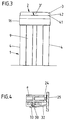
- Fig. 5 illustrates the corresponding Training particularly descriptive, but also the cross sections, for example Fig. 8, clearly show the material-saving rib structure.
- the two aprons 11, which are spaced apart in front of the narrow side walls 9, run into the broad side walls 4 at the same level.
- the cover 2 which can be fitted from above and also overlaps the lower-lying section of the opening edge 5, forms a cover d that overlaps the support rails 7 from above. H. touching down device 14.
- the latter is formed by a transverse wall 15 of the cover 2.
- the transverse wall 15 extends at a distance from the cover edge 16 located there, which ends on the underside at the same height as the other cover wall sections.
- the continuously horizontal end edge 17 of the cover 2 extends in height to the lower edge of the aprons 11 (cf. FIG. 6).
- the lid edge 16 merges into one horizontal lid cover 19 via one or two jump zones 18.
- Said folding handle 3 is mounted in the area of this lid cover 19.
- the geometric folding axis x-x runs horizontally in the vertical longitudinal center plane E-E of the carrying case. This results in a balanced slope or alignment of the lower case part 1 when carrying.
- the upward end face of the supporting webs 8 can be corrugated in accordance with the width of the hooks 10.
- the handle designed as a folding handle 3 is used to lock the lid 2 on the lower case 1.
- the locking and unlocking position is brought about depending on the position of the folding handle.
- the lid 2 In the so-called grip position shown in FIG. 8 the lid 2 is locked via the folding handle 3 on the lower case 1. 7 shows the unlocked position.
- the U-shaped folding handle 3 continues beyond the geometric folding axis xx into a lever arm a, which together with the leg b representing the U-legs 3 'of the folding handle 3 forms a double arm.
- Each lever arm a extends inside the cover 2 and, for this purpose, extends through a slot 20 in the cover cover 19.
- both lever arms a are each provided with a retaining lug 21.
- the latter are directed away from each other and, when the folding handle 3 is in the gripping position, engage under a counter nose 22 of the lower case part 1.
- the counter nose 22 extends at a corresponding distance below the geometric folding axis x-x, that is to say lying in the longitudinal center plane E-E.
- the width measured in the horizontal, that is to say the blocking angle section, is such that a clear pivoting movement is required in order to release the locking. Every angle is 45 °.
- the retaining lug 21 is also of a corresponding width. This has a run-on slope 23 on the immersion side.
- the end of the retaining lug 21 opposite this run-up slope 23 lies under the inside of the lid cover 19 when the folding handle 3 is folded down (cf. FIG. 7).
- the lever arms a each lie in a pocket 24 which, seen in the longitudinal direction of the carrying case, is limited on the one hand by the transverse walls 15 lying further inside, essentially aligned with the narrow side wall 9 of the lower case part 1, and on the other hand outwards through the corresponding end portion of the lid edge 16.
- This space crossing walls 25 limit the pocket 24, which is closed at the top by the lid cover 19 and open at the bottom, so that the retaining lug 21 the pocket 24 to bring about the locking Can leave under-grip position.
- the walls 25 stabilize the articulation area of the folding handle 3 considerably despite the striking thin-walled material.
- the counter lugs 22 are molded in the same way.
- the supporting position of the cover 2 on the lower case part 1 is defined by end recesses 26 in the transverse walls 15 of the cover 7, the base 27 of which extends directly against the front edge of the higher section of the opening edge 5 (see FIG. 7).
- the teeth 28 engage in the corresponding tooth gaps 29.
- the lower part of the case or the entire carrying case cannot pivot around the folding axis xx.
- the slope load of the Lower case part 1 and the contents themselves thus secure the rotation blocking between the two parts due to the rotation blocking tooth engagement between the holding lugs 21 and the counter lugs 22.
- tooth gaps 29 of the counter lugs 22 are open to the interior of the case, just as the tooth gaps between the teeth 28 of the holding lugs 21 are only open in the outward direction, that is to say not continuously breached.
- the upright gripping position of the folding handle 3 is secured by latching.
- the lever arm a has on the side of the arm on which the retaining lug 21 also projects transversely, a longitudinal bar 30 oriented in the direction of extension of the lever arm a. This does not extend to the retaining lug 21, since an immersion gap 31 must remain for the counter lug 22 in between.
- a free-standing locking finger 32 interacts with the free-standing section of this longitudinal bar 30 (cf. FIGS. 4 and 8).
- the latching finger 32 is rooted in one wall 25 of the pocket 24.
- the latching finger 32 lies in the spacing area between the top of the counter nose 22 and the bottom of the folding handle 3 or its storage zone.
- the locking head 33 of the locking finger 32 takes into account a locking flank shape that makes the spring force of the locking finger overcome.
- the spring force of the locking finger is based on the resilience of the material. A certain preload can be taken into account.
- geometric folding axis xx are to be explained below. It is physically formed by two directed against each other Axle stub 34. The latter go from the inside of the legs 3 'of the U-shaped folding handle 3.
- the associated bearing eyes are molded-on sections of the lid cover 19, ring pockets 35 which are open to the outside. These cup-like structures have a radially open plug-in assignment opening 36 for the latching entry of the axle stub 34. (Reference is made to FIGS. 11 and 12). 12 is also clearly evident that the plug assignment opening 36 has a latching flank 37 which cooperates with a latching cam 38 of the stub axle 34.
- Said latching cam 38 is located on a secant-shaped flattening 39 of the basically cylindrical stub axle 34.
- the plug-assignment latching position is essentially identical to the fold-down position of the folding handle 3, i. that is, the then horizontally aligned secant-shaped flattening 39 can freely enter the plug assignment opening 36.
- the latching cam 38 still projects above this flank, the latching cam 38 and latching flank 37 must deform somewhat using the restoring force of the material, so that when this zone is passed there is a secure binding position of the folding handle 3 on the cover 2.
- the folding handle 3 lies lower than the top of the horizontal lid cover 19. This is based on a structural measure in such a way that the folding handle 3 in the folded-down position (FIG. 7) in the outline of the carrying case immersed.
- the U-shaped folding handle 3 is therefore fully immersed in the outline of the suspension file Carrying case.
- the recess of the cover 2 which receives the folding handle 3 and which can be practically designated as a negative shape is designated by 40.
- the handle body is convexly rounded at least on its outer surface and the bottom of the recess 40 also merges into the lid edge 16 via such a transverse curve 41, a gripping gap 42 remains. Because of this gap 42, the folding handle 3 can be comfortably gripped in its inserted position. The corresponding hiding position of the folding handle 3 provides a convenient stackability of the suspension file carrying case.
- a rib structure is used in the usual manner in the field of injection molding, which does not require any further discussion.
- the lid 2 When the folding handle 3 is folded down, the lid 2 can be removed from its protective overlay position of the lower case part 1 by simply lifting the lid 2. If the carrying case is to be transported suitably, then only the folding handle 3 needs to be transferred to the handle position. In this case, by engaging under the retaining lugs 21 under the counter lugs 22, the lid 2 is automatically locked on the lower case part 1. This upward folding position is secured by the latching finger 32. A pendulum protection is achieved by the slope-related locking between the retaining lugs 21 and corresponding counter lugs 22 by the teeth 28 engaging in the tooth gaps 29.
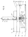
- FIG. 13 shows a non-positive connection of the cover 2 to the lower case part 1 when the folding handle 3 is upright. Magnetic material is used for this. Specifically, the procedure is such that both the retaining lug 21 now associated with the folding axis x-x contains a permanent magnet 43 and the counter lug 22 now arranged below it. The permanent magnet bears the reference numeral 44. Both permanent magnets can be accommodated in pockets or can be assigned as freestanding.
- the permanent magnet 43 seated on the retaining lug 21 of the folding handle 3 rests on an elastic body 45 such as, for example, rubber, foam or the like. He (43) therefore pulls against the other permanent magnet 44 with increasing overlap position or in a congruent position with the other permanent magnet 44. In the corresponding folding position, the upright position of the folding handle 3 is thus secured and, moreover, the lid 2 is held on the lower part of the case.
- the sides of the arc 21 ', 22' equipped with magnetic bodies are concavely or convexly curved in accordance with the course of the circular arc of the pivoting of the handle.
- the variant explained can also be developed in such a way that the magnetically equipped holding lugs 21 engage under the corresponding counter lugs 22 of the lower case part 1.
- the locking finger 32 securing the upright position of the folding handle is also dispensable in this case.
- the force-locking means would only be the upright position of the folding handle secure while tying the lid 2 via folding handle 3 via positive locking.
Landscapes
- Purses, Travelling Bags, Baskets, Or Suitcases (AREA)
- Lubricants (AREA)
- Container Filling Or Packaging Operations (AREA)
Applications Claiming Priority (2)
| Application Number | Priority Date | Filing Date | Title |
|---|---|---|---|
| DE9000819U DE9000819U1 (de) | 1990-01-25 | 1990-01-25 | Registratur-Tragkoffer |
| DE9000819U | 1990-01-25 |
Publications (3)
| Publication Number | Publication Date |
|---|---|
| EP0438702A2 EP0438702A2 (de) | 1991-07-31 |
| EP0438702A3 EP0438702A3 (en) | 1991-11-27 |
| EP0438702B1 true EP0438702B1 (de) | 1994-03-23 |
Family
ID=6850344
Family Applications (1)
| Application Number | Title | Priority Date | Filing Date |
|---|---|---|---|
| EP90123972A Expired - Lifetime EP0438702B1 (de) | 1990-01-25 | 1990-12-12 | Registratur-Tragkoffer |
Country Status (5)
| Country | Link |
|---|---|
| EP (1) | EP0438702B1 (da) |
| AT (1) | ATE103144T1 (da) |
| DE (2) | DE9000819U1 (da) |
| DK (1) | DK0438702T3 (da) |
| ES (1) | ES2051445T3 (da) |
Families Citing this family (3)
| Publication number | Priority date | Publication date | Assignee | Title |
|---|---|---|---|---|
| IT221561Z2 (it) * | 1991-01-16 | 1994-07-22 | Mh Way Srl | Maniglia ripieghevole per borse e simili |
| DE29600948U1 (de) * | 1996-01-12 | 1996-04-04 | Herlitz AG, 13507 Berlin | Tragkoffer |
| DE102015118621B4 (de) | 2015-10-30 | 2024-09-19 | Vorwerk & Co. Interholding Gmbh | Reinigungsgerät mit einem schwenkbaren Handgriff |
Family Cites Families (11)
| Publication number | Priority date | Publication date | Assignee | Title |
|---|---|---|---|---|
| BE448171A (da) * | ||||
| US4157763A (en) * | 1977-12-02 | 1979-06-12 | Bell & Howell Company | Rotatable carrying handle arrangement |
| DE2809705C2 (de) * | 1978-03-07 | 1982-08-05 | Fa. Louis Leitz, 7000 Stuttgart | Behälter für Hängehefter u.dgl. |
| US4330050A (en) * | 1980-05-23 | 1982-05-18 | Sangster Marshall A | Portable article carrying case |
| DE3027871A1 (de) * | 1980-07-23 | 1982-03-04 | Fa. Louis Leitz, 7000 Stuttgart | Tragbehaelter fuer schriftgut |
| US4505388A (en) * | 1982-12-08 | 1985-03-19 | Esselte Pendaflex Corporation | Expandable portable file |
| DE8321924U1 (de) * | 1983-07-28 | 1983-11-24 | Herlitz Ag, 1000 Berlin | Hängeregistraturbehälter |
| DE8610225U1 (de) * | 1986-04-11 | 1986-06-05 | The Decor Corp. Pty. Ldt., Victoria | Kühlbarer Träger |
| DE8611920U1 (de) * | 1986-04-30 | 1986-08-21 | IMEXO-Fornoff GmbH, 6050 Offenbach | Klappgriff für Rollenkoffer |
| US4775072A (en) * | 1987-07-29 | 1988-10-04 | The Coleman Company, Inc. | Handle assembly for insulated container |
| JPH01161372U (da) * | 1988-04-28 | 1989-11-09 |
-
1990
- 1990-01-25 DE DE9000819U patent/DE9000819U1/de not_active Expired - Lifetime
- 1990-12-12 DE DE90123972T patent/DE59005111D1/de not_active Expired - Fee Related
- 1990-12-12 DK DK90123972.3T patent/DK0438702T3/da active
- 1990-12-12 AT AT90123972T patent/ATE103144T1/de not_active IP Right Cessation
- 1990-12-12 ES ES90123972T patent/ES2051445T3/es not_active Expired - Fee Related
- 1990-12-12 EP EP90123972A patent/EP0438702B1/de not_active Expired - Lifetime
Also Published As
| Publication number | Publication date |
|---|---|
| EP0438702A3 (en) | 1991-11-27 |
| DE59005111D1 (de) | 1994-04-28 |
| DE9000819U1 (de) | 1991-05-23 |
| ES2051445T3 (es) | 1994-06-16 |
| ATE103144T1 (de) | 1994-04-15 |
| DK0438702T3 (da) | 1994-07-25 |
| EP0438702A2 (de) | 1991-07-31 |
Similar Documents
| Publication | Publication Date | Title |
|---|---|---|
| DE19963248A1 (de) | Abfallbehälter und Verfahren zu dessen Herstellung und Zusammenbau | |
| DE4143145A1 (de) | Verrigelungssystem fuer einen abfallbehaelter | |
| DE69331131T2 (de) | Koffer | |
| DE102018213489A1 (de) | Hängetaschengestell und Hängetasche | |
| EP0457959B1 (de) | Koffer mit Rollen | |
| EP0438702B1 (de) | Registratur-Tragkoffer | |
| WO2016015715A1 (de) | Vorrichtung zur aufnahme von paketen oder anderen lieferungen | |
| EP0740630A1 (de) | Als gitterbox ausgebildeter transportbehälter | |
| DE202009018589U1 (de) | Behälteranordnung | |
| AT400702B (de) | Kasten aus kunststoff | |
| DE10216804C1 (de) | Bausatz mit Steckgriffen | |
| DE7529183U (de) | Stapelbarer Transportbehälter | |
| DE4216991C2 (de) | Tragbarer Mülleimer | |
| DE10118503B4 (de) | Behälter, insbesondere Postbehälter | |
| CH695684A5 (de) | Behälter für Lebensmittel. | |
| CH692498A5 (de) | Lasttragkörper für einen Gepäckträger. | |
| DE9402531U1 (de) | Als Gitterbox ausgebildeter Transportbehälter | |
| DE9408948U1 (de) | Lager- und Transportkasten | |
| DE2505910A1 (de) | Fahrbarer transportbehaelter | |
| DE9000974U1 (de) | Haushaltsbox aus Kunststoff | |
| DE102020113845A1 (de) | Behälter zur Aufbewahrung von Wertgegenständen | |
| DE8101353U1 (de) | Sparbehaelter | |
| DE29504866U1 (de) | Zusammenklappbarer Drahtkorb | |
| DE202020102949U1 (de) | Behälter zur Aufbewahrung von Wertgegenständen | |
| DE8909059U1 (de) | Klappe |
Legal Events
| Date | Code | Title | Description |
|---|---|---|---|
| PUAI | Public reference made under article 153(3) epc to a published international application that has entered the european phase |
Free format text: ORIGINAL CODE: 0009012 |
|
| AK | Designated contracting states |
Kind code of ref document: A2 Designated state(s): AT BE CH DE DK ES FR GB GR IT LI LU NL SE |
|
| PUAL | Search report despatched |
Free format text: ORIGINAL CODE: 0009013 |
|
| AK | Designated contracting states |
Kind code of ref document: A3 Designated state(s): AT BE CH DE DK ES FR GB GR IT LI LU NL SE |
|
| 17P | Request for examination filed |
Effective date: 19920217 |
|
| 17Q | First examination report despatched |
Effective date: 19930623 |
|
| GRAA | (expected) grant |
Free format text: ORIGINAL CODE: 0009210 |
|
| AK | Designated contracting states |
Kind code of ref document: B1 Designated state(s): AT BE CH DE DK ES FR GB GR IT LI LU NL SE |
|
| PG25 | Lapsed in a contracting state [announced via postgrant information from national office to epo] |
Ref country code: SE Free format text: THE PATENT HAS BEEN ANNULLED BY A DECISION OF A NATIONAL AUTHORITY Effective date: 19940323 |
|
| REF | Corresponds to: |
Ref document number: 103144 Country of ref document: AT Date of ref document: 19940415 Kind code of ref document: T |
|
| REF | Corresponds to: |
Ref document number: 59005111 Country of ref document: DE Date of ref document: 19940428 |
|
| GBT | Gb: translation of ep patent filed (gb section 77(6)(a)/1977) |
Effective date: 19940413 |
|
| ET | Fr: translation filed | ||
| ITF | It: translation for a ep patent filed | ||
| REG | Reference to a national code |
Ref country code: ES Ref legal event code: FG2A Ref document number: 2051445 Country of ref document: ES Kind code of ref document: T3 |
|
| REG | Reference to a national code |
Ref country code: DK Ref legal event code: T3 |
|
| REG | Reference to a national code |
Ref country code: GR Ref legal event code: FG4A Free format text: 3011861 |
|
| PLBE | No opposition filed within time limit |
Free format text: ORIGINAL CODE: 0009261 |
|
| STAA | Information on the status of an ep patent application or granted ep patent |
Free format text: STATUS: NO OPPOSITION FILED WITHIN TIME LIMIT |
|
| 26N | No opposition filed | ||
| PGFP | Annual fee paid to national office [announced via postgrant information from national office to epo] |
Ref country code: FR Payment date: 19961119 Year of fee payment: 7 |
|
| PGFP | Annual fee paid to national office [announced via postgrant information from national office to epo] |
Ref country code: CH Payment date: 19961122 Year of fee payment: 7 Ref country code: AT Payment date: 19961122 Year of fee payment: 7 |
|
| PGFP | Annual fee paid to national office [announced via postgrant information from national office to epo] |
Ref country code: LU Payment date: 19961201 Year of fee payment: 7 |
|
| PGFP | Annual fee paid to national office [announced via postgrant information from national office to epo] |
Ref country code: GB Payment date: 19961203 Year of fee payment: 7 |
|
| PGFP | Annual fee paid to national office [announced via postgrant information from national office to epo] |
Ref country code: DK Payment date: 19970102 Year of fee payment: 7 |
|
| PGFP | Annual fee paid to national office [announced via postgrant information from national office to epo] |
Ref country code: BE Payment date: 19970214 Year of fee payment: 7 |
|
| PG25 | Lapsed in a contracting state [announced via postgrant information from national office to epo] |
Ref country code: LU Free format text: LAPSE BECAUSE OF NON-PAYMENT OF DUE FEES Effective date: 19971212 Ref country code: GB Free format text: LAPSE BECAUSE OF NON-PAYMENT OF DUE FEES Effective date: 19971212 Ref country code: DK Free format text: LAPSE BECAUSE OF NON-PAYMENT OF DUE FEES Effective date: 19971212 Ref country code: AT Free format text: LAPSE BECAUSE OF NON-PAYMENT OF DUE FEES Effective date: 19971212 |
|
| PG25 | Lapsed in a contracting state [announced via postgrant information from national office to epo] |
Ref country code: LI Free format text: LAPSE BECAUSE OF NON-PAYMENT OF DUE FEES Effective date: 19971231 Ref country code: FR Free format text: THE PATENT HAS BEEN ANNULLED BY A DECISION OF A NATIONAL AUTHORITY Effective date: 19971231 Ref country code: CH Free format text: LAPSE BECAUSE OF NON-PAYMENT OF DUE FEES Effective date: 19971231 Ref country code: BE Free format text: LAPSE BECAUSE OF NON-PAYMENT OF DUE FEES Effective date: 19971231 |
|
| BERE | Be: lapsed |
Owner name: ELBA-ORDNER-FABRIK KRAUT & MEIENBORN G.M.B.H. & C Effective date: 19971231 |
|
| GBPC | Gb: european patent ceased through non-payment of renewal fee |
Effective date: 19971212 |
|
| REG | Reference to a national code |
Ref country code: CH Ref legal event code: PL |
|
| REG | Reference to a national code |
Ref country code: FR Ref legal event code: ST |
|
| PGFP | Annual fee paid to national office [announced via postgrant information from national office to epo] |
Ref country code: NL Payment date: 19981223 Year of fee payment: 9 |
|
| PGFP | Annual fee paid to national office [announced via postgrant information from national office to epo] |
Ref country code: GR Payment date: 19981230 Year of fee payment: 9 |
|
| PGFP | Annual fee paid to national office [announced via postgrant information from national office to epo] |
Ref country code: ES Payment date: 19981231 Year of fee payment: 9 |
|
| PG25 | Lapsed in a contracting state [announced via postgrant information from national office to epo] |
Ref country code: GR Free format text: LAPSE BECAUSE OF NON-PAYMENT OF DUE FEES Effective date: 19991231 |
|
| PG25 | Lapsed in a contracting state [announced via postgrant information from national office to epo] |
Ref country code: NL Free format text: LAPSE BECAUSE OF NON-PAYMENT OF DUE FEES Effective date: 20000701 |
|
| NLV4 | Nl: lapsed or anulled due to non-payment of the annual fee |
Effective date: 20000701 |
|
| PG25 | Lapsed in a contracting state [announced via postgrant information from national office to epo] |
Ref country code: ES Free format text: LAPSE BECAUSE OF NON-PAYMENT OF DUE FEES Effective date: 20001213 |
|
| PGFP | Annual fee paid to national office [announced via postgrant information from national office to epo] |
Ref country code: DE Payment date: 20001229 Year of fee payment: 11 |
|
| REG | Reference to a national code |
Ref country code: DK Ref legal event code: EBP |
|
| PG25 | Lapsed in a contracting state [announced via postgrant information from national office to epo] |
Ref country code: DE Free format text: LAPSE BECAUSE OF NON-PAYMENT OF DUE FEES Effective date: 20020702 |
|
| REG | Reference to a national code |
Ref country code: ES Ref legal event code: FD2A Effective date: 20010113 |
|
| PG25 | Lapsed in a contracting state [announced via postgrant information from national office to epo] |
Ref country code: IT Free format text: LAPSE BECAUSE OF NON-PAYMENT OF DUE FEES Effective date: 20051212 |