EP0438785A1 - Attache pour bobines - Google Patents
Attache pour bobines Download PDFInfo
- Publication number
- EP0438785A1 EP0438785A1 EP90125527A EP90125527A EP0438785A1 EP 0438785 A1 EP0438785 A1 EP 0438785A1 EP 90125527 A EP90125527 A EP 90125527A EP 90125527 A EP90125527 A EP 90125527A EP 0438785 A1 EP0438785 A1 EP 0438785A1
- Authority
- EP
- European Patent Office
- Prior art keywords
- holder
- particular according
- coil holder
- rod
- mounting
- Prior art date
- Legal status (The legal status is an assumption and is not a legal conclusion. Google has not performed a legal analysis and makes no representation as to the accuracy of the status listed.)
- Withdrawn
Links
- 230000001154 acute effect Effects 0.000 claims description 3
- 230000014759 maintenance of location Effects 0.000 abstract 1
- 229910000831 Steel Inorganic materials 0.000 description 4
- 239000010959 steel Substances 0.000 description 4
- 239000007787 solid Substances 0.000 description 3
- 238000011161 development Methods 0.000 description 2
- 230000018109 developmental process Effects 0.000 description 2
- 239000004033 plastic Substances 0.000 description 2
- 210000000988 bone and bone Anatomy 0.000 description 1
- 230000000694 effects Effects 0.000 description 1
- 210000000629 knee joint Anatomy 0.000 description 1
- 238000004519 manufacturing process Methods 0.000 description 1
Images



Classifications
-
- B—PERFORMING OPERATIONS; TRANSPORTING
- B65—CONVEYING; PACKING; STORING; HANDLING THIN OR FILAMENTARY MATERIAL
- B65H—HANDLING THIN OR FILAMENTARY MATERIAL, e.g. SHEETS, WEBS, CABLES
- B65H49/00—Unwinding or paying-out filamentary material; Supporting, storing or transporting packages from which filamentary material is to be withdrawn or paid-out
- B65H49/02—Methods or apparatus in which packages do not rotate
- B65H49/04—Package-supporting devices
- B65H49/06—Package-supporting devices for a single operative package
-
- B—PERFORMING OPERATIONS; TRANSPORTING
- B65—CONVEYING; PACKING; STORING; HANDLING THIN OR FILAMENTARY MATERIAL
- B65H—HANDLING THIN OR FILAMENTARY MATERIAL, e.g. SHEETS, WEBS, CABLES
- B65H2701/00—Handled material; Storage means
- B65H2701/30—Handled filamentary material
- B65H2701/31—Textiles threads or artificial strands of filaments
Definitions
- the invention relates to a bobbin holder for bobbins with a mounting base and a mounting rod, for extension through a bobbin, the mounting rod having a spring finger projecting on one side for the spring-loaded clamping system on a bobbin inner wall.
- a bobbin holder for bobbins is known in which a nose is formed at the front free end of the holding rod against which the bobbin bears. Furthermore, a rear counter-holder is provided, which rests on the end of the coil former facing away from the nose in the assembled state. Alternatively, a knee joint is provided, which is biased by a tension spring extending in the axial direction of the mounting rod. Here, however, the rear bracket for the bobbin is eliminated.
- a coil holder of the type assumed at the outset is known from FR-PS 606 892, a steel wire being articulated at its free end to a holder rod arranged on a holder part.
- This steel wire is designed in an arc shape and in its lower end region breaks through a recess in a mounting base.
- a resilient clamp holding system on a coil body inner wall is realized here by means of a tension spring, with one end of the tension spring being fastened to the mounting base part and the other end being hooked into the end of the steel wire shaped into an eyelet.
- a stop arranged in the mounting base part serves for the spring-preloaded end position of the steel wire.
- the object of the present invention is to design a generic coil holder in a structurally simple and functionally optimal manner such that radial movements of the coil body are also possible to a certain extent, but the friction stress is kept as low as possible or is eliminated.
- a coil holder in which the coil body can be held on the holding rod between a catch behind the free end of the holding rod and a support ring which is adjustable and fixable on the holding rod.
- the support ring can therefore be fixed in place separately, for example, by means of a screw.
- a narrow mounting tolerance for the coil body can be set without the support ring or a rear support with pre-tensioning abutting the end of the coil body and pressing it against the front catch behind.
- the spring finger is particularly advantageous to design the spring finger by means of a helical spring.
- This spring finger which is designed as a helical spring, in particular a tension spring, has a relatively high degree of mobility in almost all directions, as a result of which an optimal clamp mounting system is achieved.
- the radial movements of the coil body that occur in practice are caused by the spring finger involved, whereby this is always shifted back into its basic position by the large restoring effect of the coil spring.
- a floating bearing is realized by this configuration.
- the spring finger from plastic, solid rubber or the like.
- a spring finger made of solid rubber for example, has a relative elasticity in the axial direction. It proves to be particularly advantageous here that the spring finger is rounded at its free end.
- a ball head is assigned to the spring finger at its free end, which supports optimal, damage-free mounting, storage and removal of the coil body.
- This ball head can be soldered or glued to coil springs and molded directly onto plastic or solid rubber spring fingers.
- the spring finger runs straight in the unloaded state.
- the holder rod has two spring fingers. This means that even larger bobbins are safely stored in the bobbin holder.
- the spring fingers preferably form the same angle with the mounting rod.
- the invention also proposes that the spring fingers enclose angles of different angles to the mounting rod, which ensures that both cylindrical and conically designed bobbins are secured against tipping on the bobbin holder.
- a catch behind is formed on the free end of the support rod. Even if the bobbin holder is arranged overhead, the bobbin cannot slide off the bobbin holder.
- the latching rear grip is designed to be adjustable. In order to realize this adjustability of the latching rear handle, it is provided that the adjustable latching rear handle is designed as a disk having an elongated hole.
- the disk In the case of a bobbin placed on the bobbin holder, the disk is set such that it overlaps the end face of the bobbin without protruding into the area of the yarn package. If a bobbin with a smaller sheath thickness, for example, is placed, the disc is adjusted until it leaves the area of the yarn package.
- the mounting base part In order to compensate in particular for the axiality of the plugged-on bobbin for fastening the mounting base part, it is provided that the mounting base part has an eccentric mounting receptacle for the mounting rod. It finally proves to be particularly advantageous that the mounting base has a plurality of mounting receptacles with different distances from the central axis of the mounting base. This configuration can be implemented, for example, in the form of a turret-type eccentric adjusting disk.
- the coil holder 1 is composed of a holder base part 2, a holder rod 3, a length-adjustable support ring 4 and two spring fingers 5 and 6 projecting from the holder rod 3 on one side.
- the support ring 4 ensures that the bobbin 25 does not tip back or shift in the direction of the support ring 4.
- the bobbin 25 - after appropriate adjustment of the support ring 4 - between the locking rear grip (adjusting disc 15) and the support ring 4 so that it does not slide off the coil holder even when plugged from top to bottom.
- the mounting base 2 is cylindrical in shape and has a bore 7 near its central axis for receiving a mounting axis 8.
- a radial bore 9 extending from the outer wall of the mounting base 2 and extending into the bore 7 receives a grub screw 10 which acts on the mounting axis 8 and this captivates in the bore 7.
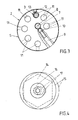
- the mounting base part 2 is designed as a revolver-like eccentric adjusting disk S, seven receiving bores 11 being arranged spirally around the bore 7.
- One of the receiving bores 11 is penetrated by the mounting rod 3, which is designed as a threaded rod, said mounting rod 3 being fixed by a locking screw 12 arranged radially in the mounting base part 2.
- the support rod 3 is composed of a threaded rod 13 and a hexagonal profile 14 arranged at its upper end. On its end face, the hexagonal profile 14 has an axial threaded hole (not shown) for fastening an adjusting disc 15 by means of a screw 16.
- This adjusting disc 15 has an elongated hole 17 in the center through which the shaft of the screw 16 engages.
- the spring fingers 5 and 6 are arranged at a distance from one another on one side of the hexagonal profile 14 of the holding rod 3. These are designed as coil springs 18 and are arranged on the mounting rod 3 such that they each enclose an angle alpha of approximately 60 ° to the plane of the hexagonal profile 14, the free ends 19 of the coil springs 18 pointing in the direction of the mounting base part 2.
- a ball head 20 is soldered to the coil springs 18 at the free ends 19.
- the support ring 4 is assigned to the section of the mounting rod 3 designed as a threaded rod 13.
- This support ring 4 is composed of a cylindrical ring section 21 and a smaller-sized, cylindrical centering section 22, both parts being penetrated by an axial bore 23, the diameter of which corresponds approximately to that of the threaded rod 13.
- the ring section 21 also has a radial bore for receiving a knurled screw 24.
- An attached bobbin 25 (see FIG. 5) is supported on the one hand with its inner wall 26 of the bobbin on the side of the hexagonal profile 14 facing away from the spring fingers 5 and 6 and on the other hand is held in a clamping system by means of the spring fingers 5 and 6.
- the 5 bobbin 25 is conical, which due to the abutment of the bobbin 25 on the hexagonal profile 14 has the consequence that the axis x of the bobbin 25 does not run parallel to the support rod 3.
- the axiality of the attached bobbin 25 to the fastening axis 8 is compensated for by the spiral arrangement of the receiving bores 11 in the base part 2. It is only necessary to insert the mounting rod 3 into the corresponding receiving bore 11.
- the coil body 25 is secured in the direction of the mounting base part 2 by means of the support ring 4.
- the coil body inner wall 26 is supported on the outer wall of the centering section 22, while the end face of the ring section 21 facing it acts on the underside of the coil body 25.
- the support ring 4 is fixed to the mounting rod 3 by means of the knurled screw 24.
- the bobbin 25 is now caught between the support ring 4 and the adjusting disk 15, the adjusting disk 15 being adjusted by means of its slot opening 17 in such a way that it acts on the end face of the bobbin wall without protruding into the region of the yarn reel 27.
- the support ring 4 is adjusted by means of the helical screws 24 so that there is a game between the end faces of the coil body and the support ring or the front catch behind when the coil body 25 is inserted.
- the game is a total of 2 mm.
- the radial movements of the bobbin 25 occurring in practice can, as shown in dash-dotted lines in FIG. 6, be carried out by the spring fingers 5 and 6 designed as a helical spring 18. There is no stress on the inside of the coil body 26.
- the bobbin 25 is pulled off the bobbin holder 1 in the simplest way by moving the bobbin 25 against the spring force of the spring fingers 5 and 6 in the direction of the mounting rod 3, the bobbin wall leaving the area of the adjusting disc 15.
- the coil former 25 can now be pulled off the coil holder 1 in the axial direction. It proves to be a great advantage that the free ends of the spring fingers 5 and 6 are equipped with ball heads 20, since this prevents the spring fingers 5 and 6 from getting caught.
- FIGS. 7 and 8 once again illustrate how the axiality of the attached coil former to the fastening axis 98 is compensated.
- the conical bobbin 25 'shown in FIG. 7 has a relatively large diameter, with the result that the angle between the axis x' of the bobbin 25 'and the holding rod 3 is relatively large.
- the support rod 3 must now be inserted into a receiving bore 11 which is distant from the mounting axis 8 in order to bring the axis x 'of the coil body 25' into the area of the mounting axis 8.
- 8 shows a conical coil body 25 '' of smaller diameter. It is now necessary to insert the holding rod 3 into a receiving bore 11 located relatively close to the fastening axis 8, in order to shift the axis x ′′ of the coil former 25 ′′ into the region of the fastening axis 8.
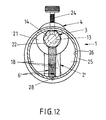
- FIGS. 9-12 The exemplary embodiment according to FIGS. 9-12 is basically of the same structure.
- the reference numbers are therefore transferred analogously, but without extensive textual repetitions.
- the mounting base 2 ' is cuboid and has in one end region a bore 7' for receiving the fastening axis 8, which is held in the bore 7 'by means of a grub screw 10.
- the mounting base part 2 ' has a receiving bore 11' for receiving the mounting rod 3.
- This bore 11 ' is arranged so that the mounting rod 3 used is directed in the direction of the fastening axis.
- the receiving bore 11 ' extends approximately at right angles to the extension of the mounting base part 2'.
- the cuboid, rod-like or otherwise suitably designed mounting base part 2 ' runs essentially straight.
- an axis of this receiving bore 11 also includes an acute angle with a plane that runs approximately parallel to a front surface of the mounting base part 2 ′ in FIG. 11.
- the acute-angled receiving bore 11 ' serves to compensate for the axiality of an attached conical bobbin to the fastening axis 8.
- the substantially vertical receiving bore 11 serves to receive essentially cylindrical bobbins. In this embodiment, too, the holding rod 3 is held in the receiving bore 11 'by means of a locking screw 12'.
- the spring fingers 5 'and 6' are of different lengths and are arranged at different angles to the hexagonal profile 14.
- the spring finger 5 ' forms an angle beta of approximately 65 ° to the hexagonal profile 14 and the spring finger 6' forms an angle gamma of approximately 70 °.
- the free ends of the spring fingers 5 'and 6' are each provided with a ring eyelet 28 formed out of the coil spring 18. These also serve for damage-free placement, storage and removal of the coil former 25.
Landscapes
- Springs (AREA)
Applications Claiming Priority (2)
| Application Number | Priority Date | Filing Date | Title |
|---|---|---|---|
| DE9000818U | 1990-01-25 | ||
| DE9000818U DE9000818U1 (de) | 1990-01-25 | 1990-01-25 | Spulenhalterung für Garnspulen |
Publications (1)
| Publication Number | Publication Date |
|---|---|
| EP0438785A1 true EP0438785A1 (fr) | 1991-07-31 |
Family
ID=6850343
Family Applications (1)
| Application Number | Title | Priority Date | Filing Date |
|---|---|---|---|
| EP90125527A Withdrawn EP0438785A1 (fr) | 1990-01-25 | 1990-12-27 | Attache pour bobines |
Country Status (2)
| Country | Link |
|---|---|
| EP (1) | EP0438785A1 (fr) |
| DE (1) | DE9000818U1 (fr) |
Cited By (4)
| Publication number | Priority date | Publication date | Assignee | Title |
|---|---|---|---|---|
| WO1993007316A1 (fr) * | 1991-10-09 | 1993-04-15 | Leif Persson | Support de bobine |
| CN103668724A (zh) * | 2013-12-25 | 2014-03-26 | 吴江市恒艺丝绸整理厂 | 一种织布机的纬纱架 |
| WO2019160661A1 (fr) * | 2018-02-13 | 2019-08-22 | Aladdin Manufacturing Corporation | Support de tube pour distribution de ligne |
| US11584609B2 (en) | 2018-02-13 | 2023-02-21 | Aladdin Manufacturing Corporation | Tube holder for line dispensing |
Families Citing this family (2)
| Publication number | Priority date | Publication date | Assignee | Title |
|---|---|---|---|---|
| DE4240663C1 (de) * | 1992-12-03 | 1994-01-27 | Mayer Textilmaschf | Spulenhalter für Garnspulen |
| DE202009007910U1 (de) | 2009-06-05 | 2009-08-20 | Oerlikon Textile Gmbh & Co. Kg | Hülsenhalter für eine Arbeitsstelle einer Offenend-Rotorspinnmaschine |
Citations (4)
| Publication number | Priority date | Publication date | Assignee | Title |
|---|---|---|---|---|
| US3659803A (en) * | 1970-06-08 | 1972-05-02 | Jakier Barski | Cone holder |
| US4063697A (en) * | 1975-09-24 | 1977-12-20 | Asa S.A. | Device for unthreading yarn from a bobbin |
| DE3119104A1 (de) * | 1981-05-14 | 1982-12-02 | W. Schlafhorst & Co, 4050 Mönchengladbach | Halter fuer eine beidseitig offene spulenhuelse einer textilspule |
| US4760977A (en) * | 1986-11-17 | 1988-08-02 | Wright Jr Joe | Yarn package holder |
Family Cites Families (4)
| Publication number | Priority date | Publication date | Assignee | Title |
|---|---|---|---|---|
| CH28338A (de) * | 1903-06-18 | 1904-04-30 | Ruegg J Sohn | Spindel |
| GB307160A (en) * | 1928-01-19 | 1929-03-07 | Frank Nasmith | Improvements in or relating to tensioning devices for controlling the delivery of yarn or the like from bobbins or like supports |
| FR1304615A (fr) * | 1961-10-28 | 1962-09-21 | Support universel pour recevoir les supports de fils textiles de tous profils, utilisés sur les cantres d'ourdissage | |
| DE7931760U1 (de) * | 1979-11-10 | 1980-02-14 | Koenig, Alfred, 7406 Moessingen | Verstellbarer halter fuer garnspulen |
-
1990
- 1990-01-25 DE DE9000818U patent/DE9000818U1/de not_active Expired - Lifetime
- 1990-12-27 EP EP90125527A patent/EP0438785A1/fr not_active Withdrawn
Patent Citations (4)
| Publication number | Priority date | Publication date | Assignee | Title |
|---|---|---|---|---|
| US3659803A (en) * | 1970-06-08 | 1972-05-02 | Jakier Barski | Cone holder |
| US4063697A (en) * | 1975-09-24 | 1977-12-20 | Asa S.A. | Device for unthreading yarn from a bobbin |
| DE3119104A1 (de) * | 1981-05-14 | 1982-12-02 | W. Schlafhorst & Co, 4050 Mönchengladbach | Halter fuer eine beidseitig offene spulenhuelse einer textilspule |
| US4760977A (en) * | 1986-11-17 | 1988-08-02 | Wright Jr Joe | Yarn package holder |
Cited By (6)
| Publication number | Priority date | Publication date | Assignee | Title |
|---|---|---|---|---|
| WO1993007316A1 (fr) * | 1991-10-09 | 1993-04-15 | Leif Persson | Support de bobine |
| CN103668724A (zh) * | 2013-12-25 | 2014-03-26 | 吴江市恒艺丝绸整理厂 | 一种织布机的纬纱架 |
| WO2019160661A1 (fr) * | 2018-02-13 | 2019-08-22 | Aladdin Manufacturing Corporation | Support de tube pour distribution de ligne |
| CN111684116A (zh) * | 2018-02-13 | 2020-09-18 | 美国阿拉丁制造公司 | 用于线分配的管支架 |
| US10968069B2 (en) | 2018-02-13 | 2021-04-06 | Aladdin Manufacturing Corporation | Tube holder for line dispensing |
| US11584609B2 (en) | 2018-02-13 | 2023-02-21 | Aladdin Manufacturing Corporation | Tube holder for line dispensing |
Also Published As
| Publication number | Publication date |
|---|---|
| DE9000818U1 (de) | 1991-05-23 |
Similar Documents
| Publication | Publication Date | Title |
|---|---|---|
| EP0315215B1 (fr) | Dispositif de fixation externe pour fragments d'os | |
| EP0134975A1 (fr) | Mandrin pour la fixation de pièces d'un outil, notamment d'un tournevis | |
| DE102007029229A1 (de) | Spannadapter für einen Katheter | |
| WO2005057025A1 (fr) | Dispositif de serrage pour tubes inseres l'un dans l'autre de facon telescopique | |
| DE3540725A1 (de) | Tamponeinsetzer | |
| DE3445885A1 (de) | Scharnier | |
| EP0438785A1 (fr) | Attache pour bobines | |
| DE10160729B4 (de) | Befestigungsanker mit Schraubenmutter | |
| EP1153560A2 (fr) | Dispositif pour supporter les boucles d'un rideau à boucles sur une tringle à rideau | |
| DE4335017A1 (de) | Betätigungsvorrichtung für Sitzträger für Stühle, insbesondere Drehstühle | |
| DE3701034C1 (de) | Einstellbarer Buegel fuer eine Brille | |
| EP3747183A1 (fr) | Support universel pour un terminal de télécommunications | |
| DE69807395T2 (de) | Angelblei | |
| DE4103110C2 (de) | Garnspulenhalter | |
| DE9317394U1 (de) | Teleskopstangenverriegelung | |
| DE3719483A1 (de) | Schraubklemme zum anschluss elektrischer leitungen | |
| DE2101082A1 (de) | Verstellbares Scharnier | |
| EP0522587A2 (fr) | Pince-étau | |
| DE8906198U1 (de) | Federanschlußglied | |
| WO2015024987A1 (fr) | Serre-joint à serrage à vis | |
| DE29604518U1 (de) | Aneurysmenklemme | |
| DE8704044U1 (de) | Spulenhalter für Textilspulen | |
| DE8628957U1 (de) | Christbaumständer | |
| DE3934163A1 (de) | Stegstuetze fuer brillen | |
| DE4092367C2 (de) | Scharnier, insbesondere für eine Fahrzeugtür |
Legal Events
| Date | Code | Title | Description |
|---|---|---|---|
| PUAI | Public reference made under article 153(3) epc to a published international application that has entered the european phase |
Free format text: ORIGINAL CODE: 0009012 |
|
| AK | Designated contracting states |
Kind code of ref document: A1 Designated state(s): AT BE CH DE DK ES FR GB GR IT LI LU NL SE |
|
| STAA | Information on the status of an ep patent application or granted ep patent |
Free format text: STATUS: THE APPLICATION IS DEEMED TO BE WITHDRAWN |
|
| 18D | Application deemed to be withdrawn |
Effective date: 19920201 |